-
216
-
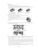
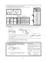
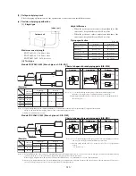
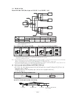
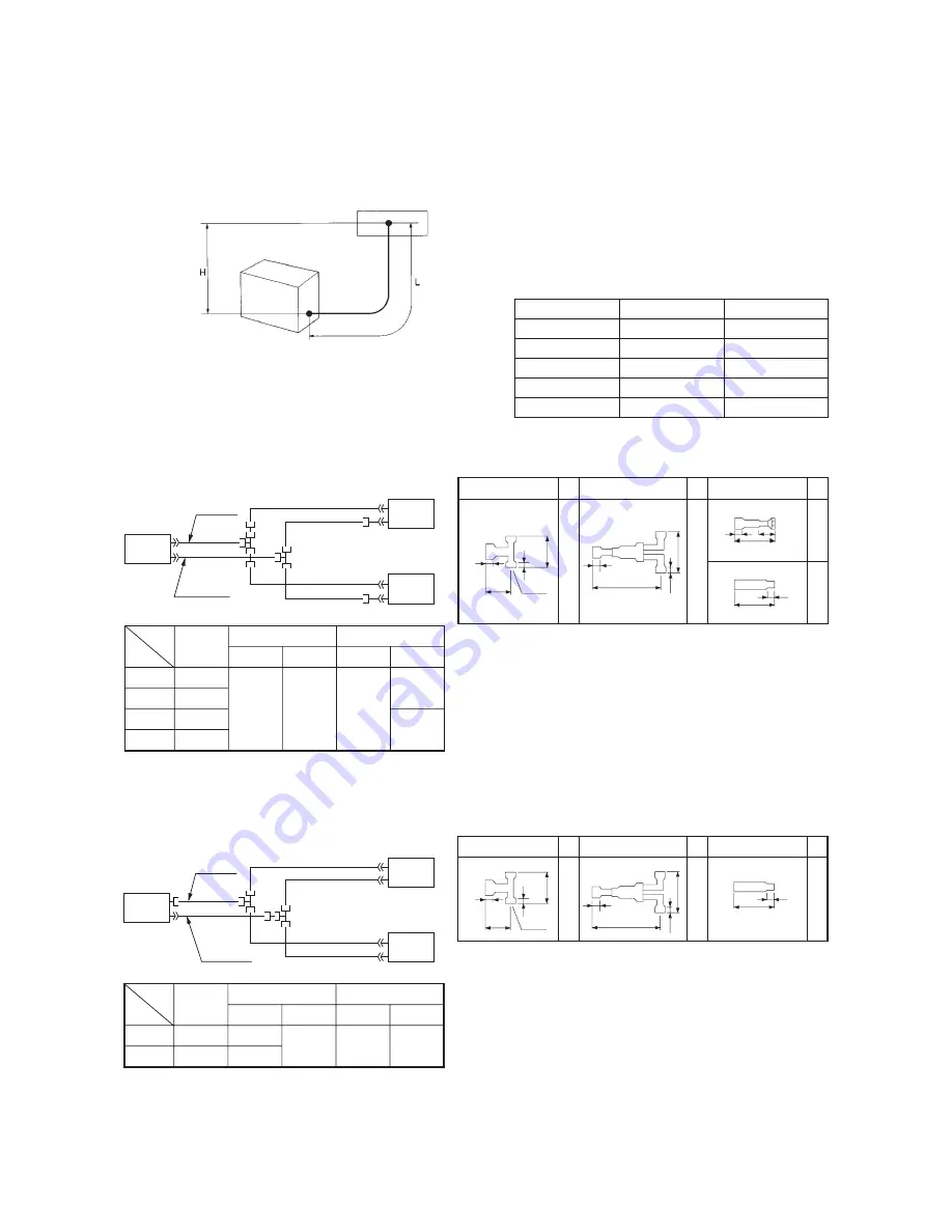
Height difference
• When the position of outdoor unit is higher than that of the
indoor unit, keep the difference H=30 m or less.
• When the position of outdoor unit is lower than that of the
indoor unit, keep the difference H=15 m or less.
Piping specifi cation
Indoor unit
Outdoor unit
(2) Refrigerant piping work
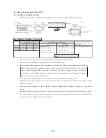
Select the piping specifi cation to fi t the specifi cation of indoor unit and installation location.
(a) Decision of piping specifi cation
(i)
Single
type
Maximum one way length
FDCVA151~251 : L=40 m or less
FDCVA302~602 : L=50 m or less
FDCVA802,1002 : L=70 m or less
(ii)
Twin
type
Models FDCVA302~602 [Branch pipe set : DIS-WA1]
Outdoor unit
Item
Liquid pipe
Indoor unit
combinations
Main pipe
Branch pipe
Main pipe
φ
9.52
×
t 0.8
φ
9.52
×
t 0.8
φ
12.7
×
t 0.8
φ
15.88
×
t 1.0
φ
15.88
×
t 1.0
Branch pipe
Gas pipe
Model
FDCVA302
FDCVA402
FDCVA502
FDCVA602
15 + 15
20 + 20
25
+
25
30
+
30
Indoor unit
Liquid line
Gas line
Chart of shapes of branch piping parts (DIS-WA1)
Gas pipe
Liquid pipe
Reducer
Mark
Mark
Mark
24
210
8
105
50
8
11
ID15.88
ID15.88
ID15.88
ID9.52
ID9.52
ID9.52
ID9.52
OD15.88
2 piece
2 piece
ID12.7
φ
6.35
flared nut
11
48
180
8
80
10
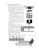
Notes (1)
to
in the drawing include parts provided in the branch piping set. It
shows the codes for the shapes of different-diameter connections.
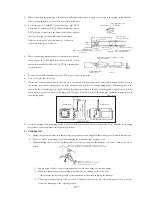
(2) Branch piping should always be arranged to have level or perpendicular branch.
(See the next page.)
Notes (1) If you are using this model in combination with the 15~25 models indoor units, use the irregular fi ttings
3
supplied with the branch
piping set and make the branch piping (branch ~ indoor unit) liquid piping size
φ
9.52.
(2)
Mark
is
4
to FDCVA302,402 only.
Models FDCVA802, 1002 [Branch pipe set : DIS-WB1]
Outdoor unit
φ
9.52
×
t 0.8
φ
12.7
×
t 0.8
φ
9.52
×
t 0.8
φ
25.4
×
t 1.0
φ
15.88
×
t 1.0
Indoor unit
Liquid line
Gas line
Chart of shapes of branch piping parts (DIS-WB1)
Gas pipe
Liquid pipe
Reducer
Mark
Mark
Mark
39
190
10
19
ID25.4
ID15.88
ID15.88
ID9.52
ID9.52
ID9.52
OD12.7
ID9.52
12
80
184
8
80
10
Item
Liquid pipe
Indoor unit
combinations
Main pipe
Branch pipe
Main pipe
Branch pipe
Gas pipe
Model
FDCVA802
FDCVA1002
40
+
40
50
+
50
Notes (1)
1
to
3
in the drawing include parts provided in the branch piping set. It shows
the codes for the shapes of different-diameter connections.
(2)
Branch piping should always be arranged to have level or perpendicular
branch.
(See the next page.)
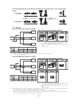
(Example)
(Example)
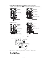
Notes (1) For model FDCVA802, always use ø12.7 mm liquid pipes, when the length of the main “L” exceeds 40 m. If ø9.52 mm pipes are used in an installation having
over 40 m piping, they can cause performance degradation and/or water leaks from an indoor unit.
When the pipes length measures 60 m or longer for the model FDCVA802, we recommend the use of a ø12.7 mm liquid main.
(2) One-way pipe length should measure 5 m at a minimum. If the pipe length measures less than 5 m, then reduce the quantity of charged refrigerant. If you need to
recover or recharge refrigerant, contact our sales agent found in your neighborhood.
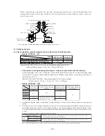
Outdoor unit model
Gas pipe
Liquid pipe
FDCVA151,201
φ
12.7
×
t 0.8
φ
6.35
×
t 0.8
FDCVA251
φ
15.88
×
t 1.0
φ
6.35
×
t 0.8
FDCVA302~602
φ
15.88
×
t 1.0
φ
9.52
×
t 0.8
FDCVA802
φ
25.4
×
t 1.0
φ
9.52
×
t 0.8
FDCVA1002
φ
25.4
×
t 1.0
φ
12.7
×
t 0.8
Unit : mm
Summary of Contents for FDCVA1002HESAR
Page 107: ... 106 60 17 150 b Wireless remote controller Unit mm ...
Page 119: ... 118 Model FDCVA1002HESAR Polar white ...
Page 133: ......


