-
250
-
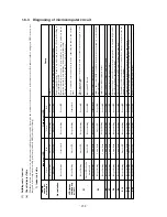
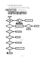
YES
YES
DC approx. 12V
NO
NO
Yes
NO
(1)
(1)
(2)
DC approx. 0V
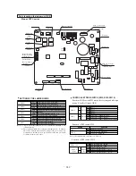
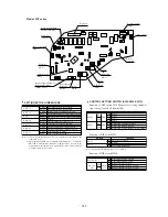
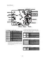
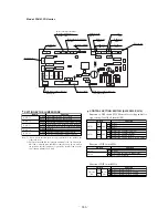
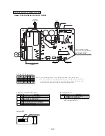
Note (1) LED Colors
402~602: Yellow LED
302, 802, 1002: Green LED
Note (1) Values in ( ) show in the case of
the FDKN series.
Note (2) Models 302~602 only.
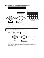
Check the inverter before replacing the power fuse.
The “ WAIT ” display remains the same
in the remote controller’s LCD ever 2 minutes
has passed since the power supply was turned
ON.
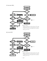
Is the LED on the outdoor
unit’s control PCB flashing?
Is the the indoor green
LED flashing?
Is the outdoor unit control PCB
red LED flashing 2 times?
Are the wires connecting the indoor
and outdoor units connected
according to specifications?
Measure the voltage between
terminals
and
of the outdoor
unit’s terminal block.
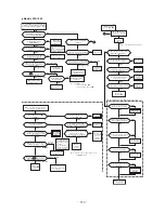
Is the inverter PCB LED
flashing?
Are communications lines CnI 1-2
between the outdoor unit control PCB
and inverter control PCB connected?
Measure the voltage between CnI
and
(
for 802 and 1002) on the communications
connector (See pages 266 to 269.)
Indoor unit
control PCB is
defect.
Indoor unit control PCB is
faulty.
Remote controller is faulty.
The Y lines in the remote
controller is disconnected.
Fix the inter connection
wiring accordingly
Connection line is
defect (disconnected),
noise.
Connect it.
Connection
lines are
disconnected.
YES
YES
YES
NO
NO
NO
NO
Is the noise filter secondary
side AC 220 ~ 240V?
NO
NO
Does the fuse on the power
supply line [30A blown].
Are the connection lines
between the noise filter and
inverter PCB good?
Are the wiring for reactor
connected correctly?
Replace the
inverter PCB.
Turn OFF the power
supply once and ON
again 3 minute later.
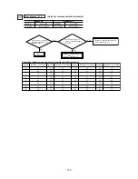
Diagnosis if the
inverter PCB LED
is OFF
Connect the
lines
correctly.
Connect/
replace the
reactor.
Replace the
noise filter.
Does it
operate
normally?
Is there a short between
phases in the noise filter?
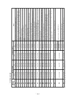
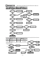
Is the indoor green LED
flashing?
Is the fuse on the indoor unit
control PCB OK?
Is the outdoor red LED
flashing 2 times?
Are the wires connecting the indoor
and outdoor units connected according
to specifications?
Measure the voltage between
terminals
and
of the
outdoor unit’s terminal block.
Is the voltage on the outdoor
unit’s transformer secondary
side (red – red) AC15V (14V) ?
Is the voltage between the red and
black wires in the remote
controller DC10~11V when the
remote controller is disconnected?
Remote controller does not display
after the power is turned on.
Is there a short between phases in
the inverter PCB input terminals?
Is the electrolytic capacitor
anomalous?
Is the power transistor module
broken or burned out?
Replace the
noise filter.
Exchange
the fuse
Transformer
defect
The remote
controller
wires are
short
circuited.
Repair the
connection
lines.
Remote
controller
defect
Outdoor unit control
PCB defect
Connection wires are
faulty (disconnection)
Noise
The indoor/outdoor
control PCB is faulty.
The remote controller
is faulty.
The X or Z lines in
the remote controller
are disconnected.
Indoor unit
control PCB
defect
Replace the
electrolytic
capacitor.
Is the reactor faulty?
Replace the
reactor.
Replace the
inverter PCB.
Replace the power
supply fuse.
Indoor unit control
PCB is defect.
Outdoor unit control
PCB is defect.
Replace the outdoor
fan motor
Replace the
outdoor fan
motor
A
Outdoor unit
control PCB is
defect.
Is the outdoor fan
motor faulty?
Is the outdoor fan motor faulty?
Measure the voltage between
terminals 2/N and
of the indoor
unit’s terminal block.
Measure the voltage between
terminals 2/N and
of the
indoor unit’s terminal block.
(1)
YES
YES
YES
YES
YES
YES
NO
YES
NO
NO
NO
NO
NO
Approx. 20V DC
Approx.
0V DC
Approx. 0V DC
Approx. 20V DC
NO
NO
NO
NO
YES
YES
NO
YES
YES
YES
YES
YES
DC approx. 20V
DC approx. 20V
DC approx. 0V
DC approx. 0V
YES
YES
NO
NO
NO
YES
YES
YES
NO
A
Models 302~1002
Summary of Contents for FDCVA1002HESAR
Page 107: ... 106 60 17 150 b Wireless remote controller Unit mm ...
Page 119: ... 118 Model FDCVA1002HESAR Polar white ...
Page 133: ......

