background image

-

 265 

-

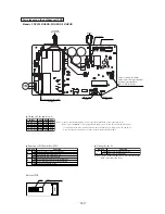
L

N

E

TB

TB

Red

White

Y/NG

LED1

Red

T1

T5

Red

White

Black

Orange

Y ello

w

UV

W

T6

T7

T8

CM

F2 (250V 20A)

CnTR

Control PCB

Power transistor module

CNI3

T2

T4

6

DC280V

F3 (250V 1A)

F5 

(20A

)

4
3
2
1

CNI2

FM

0

T21

T22

Sub PCB

(Noise filter)

T24

T25

T26

T30

T27

T28

CNI1

Or

ange

Gr

a

y

T

o indoor unit

Bro

wn

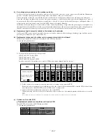
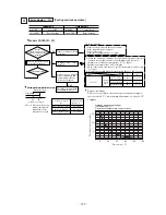
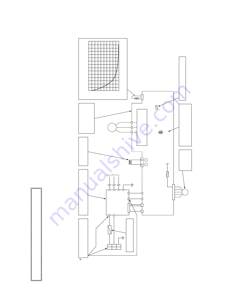
Power transistor thermistor temperature and 

resistance characteristics check

0

20

40

60

80

100

120

140

160

180

200

T

emperature (˚C)

Thermistor resistance (k

)

0

20

40

60

80

100

120

140

Power transistor module 

check: Is there a short cir-

cuit, open circuit or dam-

age? (See 

284

 page for the 

check procedure.)

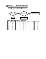
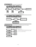
DC Reactor continuity 

Check:  50 m  or higher, 

less than 100 m

.

Fuse check: There should be continuity.

If faulty, replace the control PCB.

Noise filter check: 

There should be continuity.

There should be no shorts between phases.

LED1 (Red) check

Light continuously :

Keeps flashing :

1~3 time flash :

Normal

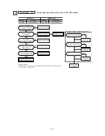
EEV

(Refer to page 

239

)

Power supply check

Measure the power supply at L.N.

(It is normal if it is AC 220/240V.)

Fuse Check: There should be 

continuity.

When the outdoor

unit fan motor is

anomalous:

(Refer to page 

280

)

Models  FDCV

A151~251HENR


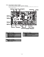
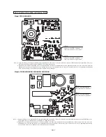
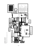
Outdoor unit check points

Check items with the *mark when the po

wer is ON.

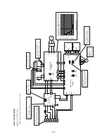
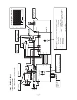
Outdoor Unit contr

oller failure dia

gnosis cir

cuit dia

gram

Summary of Contents for FDCVA1002HESAR

Page 1: ...HESP2R 602HENP2R 602HESP2R 802HESP2R 1002HESP2R FDTVA602HENT2R 602HEST2R 802HEST2R FDTVA802HESD2R 1002HESD2R FDKNVA151HEN1R 201HEN1R 251HEN1R FDKNVA302HENP1R 402HENP2R 402HESP2R 502HENP2R 502HESP2R FDKNVA602HENT2R 602HEST2R FDENVA151HEN1R 201HEN1R 251HEN1R 302HEN1R 402HEN2R 402HES2R 502HEN2R 502HES2R 602HEN2R 602HES2R FDENVA302HENP1R 402HENP2R 402HESP2R 502HENP2R 502HESP2R 602HENP2R 602HESP2R 802H...

Page 2: ... 1 TABLE OF CONTENTS 1 PACKAGED AIR CONDITIONER 2 2 MULTI TYPE V MULTI PACKAGED AIR CONDITIONER 291 3 WIRELESS KIT OPTIONAL PARTS 318 ...

Page 3: ...itations 90 1 2 3 Exterior dimensions 93 1 Indoor unit 93 2 Remote controller Optional parts 105 3 Outdoor unit 107 1 2 4 Inside view 113 1 2 5 Exterior appearance 116 1 2 6 Piping system 119 1 2 7 Selection chart 126 1 2 8 Characteristics of fan 137 1 2 9 Noise level 140 1 Indoor unit 140 2 Outdoor unit 143 1 3 ELECTRICAL DATA 144 1 3 1 Electrical wiring 144 1 Indoor unit 144 2 Outdoor unit 151 1...

Page 4: ...tness test and air purge 222 4 Refrigerant charge 223 5 Drain piping work 224 6 Electrical wiring 224 7 Setting functions using the wired remote controller 227 8 Checking operation data 232 9 Test run 233 1 6 MAINTENANCE DATA 236 1 6 1 Servicing 236 1 6 2 Trouble shooting for refrigerant circuit 237 1 6 3 Diagnosing of microcomputer circuit 238 1 Selfdiagnosis function 238 2 Procedures of trouble ...

Page 5: ... sheath is enough for conducting the wiring work between the outdoor unit and the indoor unit This contributes to simpler wiring work in the field 6 All air supply ports have auto swing louvers Only case of FDTC FDT FDEN and FDKN models The indoor fan motor has three speeds of high medium and low 7 All models have service valves protruding from the outdoor unit for faster flare connection FDCVA802...

Page 6: ...rect line start Direct line start Air flow CMM Powerful mode Hi 13 5 Me 11 5 Lo 10 Mild mode Hi 11 5 Me 10 Lo 8 41 Outside air intake Impossibility Air filter Q ty Plastic net washable 1 Shock vibration absorber Rubber sleeve for fan motor Rubber mount for compressor Electric heater W 20 Crank case heater Operation control Operation switch Wired remote control switch Optional RC E1R Wireless kit O...

Page 7: ...M Powerful mode Hi 13 5 Me 11 5 Lo 10 Mild mode Hi 11 5 Me 10 Lo 8 41 Outside air intake Impossibility Air filter Q ty Plastic net washable 1 Shock vibration absorber Rubber sleeve for fan motor Rubber mount for compressor Electric heater W 20 Crank case heater Operation control Operation switch Wired remote control switch Optional RC E1R Wireless kit Optional RCND KIT HER Indoor unit side Room te...

Page 8: ...lter Q ty Plastic net washable 1 Shock vibration absorber Rubber sleeve for fan motor Rubber mount for compressor Electric heater W 20 Crank case heater Operation control Operation switch Wired remote control switch Optional RC E1R Wireless kit Optional RCND KIT HER Indoor unit side Room temperature control Thermostat by electronics Safety equipment Internal thermostat for fan motor Frost protecti...

Page 9: ... Air filter Q ty Plastic net washable 1 Shock vibration absorber Rubber sleeve for fan motor Rubber mount for compressor Electric heater W 20 Crank case heater Operation control Operation switch Wired remote control switch Optional RC E1R Wireless kit Optional RCND KIT HER Indoor unit side Room temperature control Thermostat by electronics Safety equipment Internal thermostat for fan motor Frost p...

Page 10: ...ir filter Q ty Plastic net washable 1 Shock vibration absorber Rubber sleeve for fan motor Rubber mount for compressor Electric heater W 20 Crank case heater Operation control Operation switch Wired remote control switch Optional RC E1R Wireless kit Optional RCND KIT HER Indoor unit side Room temperature control Thermostat by electronics Safety equipment Internal thermostat for fan motor Frost pro...

Page 11: ...ilable Air filter Q ty Plastic net washable 1 Shock vibration absorber Rubber sleeve for fan motor Rubber mount for compressor Electric heater W 20 Crank case heater Operation control Operation switch Wired remote control switch Optional RC E1R Wireless kit Optional RCND KIT HER Indoor unit side Room temperature control Thermostat by electronics Safety equipment Internal thermostat for fan motor F...

Page 12: ...r filter Q ty Plastic net washable 1 Shock vibration absorber Rubber sleeve for fan motor Rubber mount for compressor Electric heater W 20 Crank case heater Operation control Operation switch Wired remote control switch Optional RC E1R Wireless kit Optional RCND KIT HER Indoor unit side Room temperature control Thermostat by electronics Safety equipment Internal thermostat for fan motor Frost prot...

Page 13: ... line start Air flow CMM Powerful mode Hi 18 Me 15 Lo 14 Mild mode Hi 15 Me 14 Lo 13 41 Outside air intake Available Air filter Q ty Plastic net washable 1 Shock vibration absorber Rubber sleeve for fan motor Rubber mount for compressor Electric heater W 20 Crank case heater Operation control Operation switch Wired remote control switch Optional RC E1R Wireless kit Optional RCN T 35W ER Indoor uni...

Page 14: ...CMM Powerful mode Hi 18 Me 15 Lo 14 Mild mode Hi 15 Me 14 Lo 13 41 Outside air intake Available Air filter Q ty Plastic net washable 1 Shock vibration absorber Rubber sleeve for fan motor Rubber mount for compressor Electric heater W 20 Crank case heater Operation control Operation switch Wired remote control switch Optional RC E1R Wireless kit Optional RCN T 35W ER Indoor unit side Room temperatu...

Page 15: ...MM Powerful mode Hi 20 Me 17 Lo 15 Mild mode Hi 17 Me 15 Lo 13 41 Outside air intake Available Air filter Q ty Plastic net washable 1 Shock vibration absorber Rubber sleeve for fan motor Rubber mount for compressor Electric heater W 20 Crank case heater Operation control Operation switch Wired remote control switch Optional RC E1R Wireless kit Optional RCN T 35W ER Indoor unit side Room temperatur...

Page 16: ... 20 Me 17 Lo 15 Mild mode Hi 17 Me 15 Lo 13 Cooling 60 Heating 48 5 Outside air intake Available Air filter Q ty Plastic net washable 1 Shock vibration absorber Rubber sleeve for fan motor Rubber mount for compressor Electric heater W 20 Crank case heater Operation control Operation switch Wired remote control switch Optional RC E1R Wireless kit Optional RCN T 35W ER Indoor unit side Room temperat...

Page 17: ...2 Lo 20 Mild mode Hi 22 Me 20 Lo 18 Cooling 75 Heating 73 Outside air intake Available Air filter Q ty Plastic net washable 1 Shock vibration absorber Rubber sleeve for fan motor Rubber mount for compressor Electric heater W 20 Crank case heater Operation control Operation switch Wired remote control switch Optional RC E1R Wireless kit Optional RCN T 35W ER Indoor unit side Room temperature contro...

Page 18: ... Lo 20 Mild mode Hi 22 Me 20 Lo 18 Cooling 75 Heating 73 Outside air intake Available Air filter Q ty Plastic net washable 1 Shock vibration absorber Rubber sleeve for fan motor Rubber mount for compressor Electric heater W 20 Crank case heater Operation control Operation switch Wired remote control switch Optional RC E1R Wireless kit Optional RCN T 35W ER Indoor unit side Room temperature control...

Page 19: ...owerful mode Hi 32 Me 29 Lo 26 Mild mode Hi 29 Me 26 Lo 23 Cooling 75 Heating 73 Outside air intake Available Air filter Q ty Plastic net washable 1 Shock vibration absorber Rubber sleeve for fan motor Rubber mount for compressor Electric heater W 20 Crank case heater Operation control Operation switch Wired remote control switch Optional RC E1R Wireless kit Optional RCN T 35W ER Indoor unit side ...

Page 20: ...erful mode Hi 32 Me 29 Lo 26 Mild mode Hi 29 Me 26 Lo 23 Cooling 75 Heating 73 Outside air intake Available Air filter Q ty Plastic net washable 1 Shock vibration absorber Rubber sleeve for fan motor Rubber mount for compressor Electric heater W 20 Crank case heater Operation control Operation switch Wired remote control switch Optional RC E1R Wireless kit Optional RCN T 35W ER Indoor unit side Ro...

Page 21: ...owerful mode Hi 34 Me 30 Lo 26 Mild mode Hi 30 Me 26 Lo 23 Cooling 75 Heating 73 Outside air intake Available Air filter Q ty Plastic net washable 1 Shock vibration absorber Rubber sleeve for fan motor Rubber mount for compressor Electric heater W 20 Crank case heater Operation control Operation switch Wired remote control switch Optional RC E1R Wireless kit Optional RCN T 35W ER Indoor unit side ...

Page 22: ...erful mode Hi 34 Me 30 Lo 26 Mild mode Hi 30 Me 26 Lo 23 Cooling 75 Heating 73 Outside air intake Available Air filter Q ty Plastic net washable 1 Shock vibration absorber Rubber sleeve for fan motor Rubber mount for compressor Electric heater W 20 Crank case heater Operation control Operation switch Wired remote control switch Optional RC E1R Wireless kit Optional RCN T 35W ER Indoor unit side Ro...

Page 23: ...Q ty Plastic net washable 1 Shock vibration absorber Rubber sleeve for fan motor Rubber mount for compressor Electric heater W 20 Crank case heater Operation control Operation switch Wired remote control switch Optional RC E1R Wireless kit Optional RCN T 35W ER Indoor unit side Room temperature control Thermostat by electronics Safety equipment Internal thermostat for fan motor Frost protection th...

Page 24: ...y Plastic net washable 1 Shock vibration absorber Rubber sleeve for fan motor Rubber mount for compressor Electric heater W 20 Crank case heater Operation control Operation switch Wired remote control switch Optional RC E1R Wireless kit Optional RCN T 35W ER Indoor unit side Room temperature control Thermostat by electronics Safety equipment Internal thermostat for fan motor Frost protection therm...

Page 25: ...lter Q ty Plastic net washable 1 Shock vibration absorber Rubber sleeve for fan motor Rubber mount for compressor Electric heater W 20 Crank case heater Operation control Operation switch Wired remote control switch Optional RC E1R Wireless kit Optional RCN T 35W ER Indoor unit side Room temperature control Thermostat by electronics Safety equipment Internal thermostat for fan motor Frost protecti...

Page 26: ... Air filter Q ty Plastic net washable 1 Shock vibration absorber Rubber sleeve for fan motor Rubber mount for compressor Electric heater W 20 Crank case heater Operation control Operation switch Wired remote control switch Optional RC E1R Wireless kit Optional RCN T 35W ER Indoor unit side Room temperature control Thermostat by electronics Safety equipment Internal thermostat for fan motor Frost p...

Page 27: ...ir filter Q ty Plastic net washable 1 Shock vibration absorber Rubber sleeve for fan motor Rubber mount for compressor Electric heater W 20 Crank case heater Operation control Operation switch Wired remote control switch Optional RC E1R Wireless kit Optional RCN T 35W ER Indoor unit side Room temperature control Thermostat by electronics Safety equipment Internal thermostat for fan motor Frost pro...

Page 28: ... Air filter Q ty Plastic net washable 1 Shock vibration absorber Rubber sleeve for fan motor Rubber mount for compressor Electric heater W 20 Crank case heater Operation control Operation switch Wired remote control switch Optional RC E1R Wireless kit Optional RCN T 35W ER Indoor unit side Room temperature control Thermostat by electronics Safety equipment Internal thermostat for fan motor Frost p...

Page 29: ...ir filter Q ty Plastic net washable 1 Shock vibration absorber Rubber sleeve for fan motor Rubber mount for compressor Electric heater W 20 Crank case heater Operation control Operation switch Wired remote control switch Optional RC E1R Wireless kit Optional RCN T 35W ER Indoor unit side Room temperature control Thermostat by electronics Safety equipment Internal thermostat for fan motor Frost pro...

Page 30: ...ter W 40 Crank case heater Operation control Operation switch Wired remote control switch Optional RC E1R Wireless kit Optional RCN T 35W ER Indoor unit side Room temperature control Thermostat by electronics Safety equipment Internal thermostat for fan motor Frost protection thermostat Internal thermostat for fan motor Anomalous discharge temperature protection Installation data Refrigerant pipin...

Page 31: ...unt for compressor Electric heater W 40 Crank case heater Operation control Operation switch Wired remote control switch Optional RC E1R Wireless kit Optional RCN T 35W ER Indoor unit side Room temperature control Thermostat by electronics Safety equipment Internal thermostat for fan motor Frost protection thermostat Internal thermostat for fan motor Anomalous discharge temperature protection Inst...

Page 32: ...e Air filter Q ty Plastic net washable 1 Shock vibration absorber Rubber sleeve for fan motor Rubber mount for compressor Electric heater W 20 Crank case heater Operation control Operation switch Wired remote control switch Optional RC E1R Wireless kit Optional RCN T 35W ER Indoor unit side Room temperature control Thermostat by electronics Safety equipment Internal thermostat for fan motor Frost ...

Page 33: ...ter Q ty Plastic net washable 1 Shock vibration absorber Rubber sleeve for fan motor Rubber mount for compressor Electric heater W 20 Crank case heater Operation control Operation switch Wired remote control switch Optional RC E1R Wireless kit Optional RCN T 35W ER Indoor unit side Room temperature control Thermostat by electronics Safety equipment Internal thermostat for fan motor Frost protectio...

Page 34: ...compressor Electric heater W 40 Crank case heater Operation control Operation switch Wired remote control switch Optional RC E1R Wireless kit Optional RCN T 35W ER Indoor unit side Room temperature control Thermostat by electronics Safety equipment Internal thermostat for fan motor Frost protection thermostat Internal thermostat for fan motor Anomalous discharge temperature protection Installation...

Page 35: ...mount for compressor Electric heater W 40 Crank case heater Operation control Operation switch Wired remote control switch Optional RC E1R Wireless kit Optional RCN T 35W ER Indoor unit side Room temperature control Thermostat by electronics Safety equipment Internal thermostat for fan motor Frost protection thermostat Internal thermostat for fan motor Anomalous discharge temperature protection In...

Page 36: ...nt for compressor Electric heater W 20 Crank case heater Operation control Operation switch Wired remote control switch Optional RC E1R Wireless kit Optional RCN T 35W ER Indoor unit side Room temperature control Thermostat by electronics Safety equipment Internal thermostat for fan motor Frost protection thermostat Internal thermostat for fan motor Anomalous discharge temperature protection Insta...

Page 37: ...t line start Air flow CMM Powerful mode Hi 12 Me 11 Lo 9 Mild mode Hi 11 Me 9 Lo 7 41 Outside air intake Unavailable Air filter Q ty Plastic net washable 2 Shock vibration absorber Rubber sleeve for fan motor Rubber mount for compressor Electric heater W 20 Crank case heater Operation control Operation switch Wireless remote control switch Optional RCN E1R Wired remote control switch Optional RC E...

Page 38: ...CMM Powerful mode Hi 12 Me 11 Lo 9 Mild mode Hi 11 Me 9 Lo 7 41 Outside air intake Unavailable Air filter Q ty Plastic net washable 2 Shock vibration absorber Rubber sleeve for fan motor Rubber mount for compressor Electric heater W 20 Crank case heater Operation control Operation switch Wireless remote control switch Optional RCN E1R Wired remote control switch Optional RC E1R Indoor unit side Ro...

Page 39: ...M Powerful mode Hi 20 Me 18 Lo 14 Mild mode Hi 18 Me 14 Lo 12 41 Outside air intake Unavailable Air filter Q ty Plastic net washable 2 Shock vibration absorber Rubber sleeve for fan motor Rubber mount for compressor Electric heater W 20 Crank case heater Operation control Operation switch Wireless remote control switch Optional RCN E1R Wired remote control switch Optional RC E1R Indoor unit side R...

Page 40: ...ow CMM Powerful mode Hi 20 Me 18 Lo 14 Mild mode Hi 18 Me 14 Lo 12 Cooling 60 Heating 48 5 Outside air intake Unavailable Air filter Q ty Plastic net washable 2 Shock vibration absorber Rubber sleeve for fan motor Rubber mount for compressor Electric heater W 20 Crank case heater Operation control Operation switch Wireless remote control switch Optional RCN E1R Wired remote control switch Optional...

Page 41: ...werful mode Hi 29 Me 26 Lo 23 Mild mode Hi 26 Me 23 Lo 21 Cooling 75 Heating 73 Outside air intake Unavailable Air filter Q ty Plastic net washable 2 Shock vibration absorber Rubber sleeve for fan motor Rubber mount for compressor Electric heater W 20 Crank case heater Operation control Operation switch Wireless remote control switch Optional RCN E1R Wired remote control switch Optional RC E1R Ind...

Page 42: ...rful mode Hi 29 Me 26 Lo 23 Mild mode Hi 26 Me 23 Lo 21 Cooling 75 Heating 73 Outside air intake Unavailable Air filter Q ty Plastic net washable 2 Shock vibration absorber Rubber sleeve for fan motor Rubber mount for compressor Electric heater W 20 Crank case heater Operation control Operation switch Wireless remote control switch Optional RCN E1R Wired remote control switch Optional RC E1R Indoo...

Page 43: ...werful mode Hi 31 Me 29 Lo 26 Mild mode Hi 29 Me 26 Lo 23 Cooling 75 Heating 73 Outside air intake Unavailable Air filter Q ty Plastic net washable 2 Shock vibration absorber Rubber sleeve for fan motor Rubber mount for compressor Electric heater W 20 Crank case heater Operation control Operation switch Wireless remote control switch Optional RCN E1R Wired remote control switch Optional RC E1R Ind...

Page 44: ...rful mode Hi 31 Me 29 Lo 26 Mild mode Hi 29 Me 26 Lo 23 Cooling 75 Heating 73 Outside air intake Unavailable Air filter Q ty Plastic net washable 2 Shock vibration absorber Rubber sleeve for fan motor Rubber mount for compressor Electric heater W 20 Crank case heater Operation control Operation switch Wireless remote control switch Optional RCN E1R Wired remote control switch Optional RC E1R Indoo...

Page 45: ...werful mode Hi 31 Me 29 Lo 26 Mild mode Hi 29 Me 26 Lo 23 Cooling 75 Heating 73 Outside air intake Unavailable Air filter Q ty Plastic net washable 2 Shock vibration absorber Rubber sleeve for fan motor Rubber mount for compressor Electric heater W 20 Crank case heater Operation control Operation switch Wireless remote control switch Optional RCN E1R Wired remote control switch Optional RC E1R Ind...

Page 46: ...rful mode Hi 31 Me 29 Lo 26 Mild mode Hi 29 Me 26 Lo 23 Cooling 75 Heating 73 Outside air intake Unavailable Air filter Q ty Plastic net washable 2 Shock vibration absorber Rubber sleeve for fan motor Rubber mount for compressor Electric heater W 20 Crank case heater Operation control Operation switch Wireless remote control switch Optional RCN E1R Wired remote control switch Optional RC E1R Indoo...

Page 47: ... Rubber sleeve for fan motor Rubber mount for compressor Electric heater W 20 Crank case heater Operation control Operation switch Wireless remote control switch Optional RCN E1R Wired remote control switch Optional RC E1R Indoor unit side Room temperature control Thermostat by electronics Safety equipment Internal thermostat for fan motor Frost protection thermostat Internal thermostat for fan mo...

Page 48: ...sorber Rubber sleeve for fan motor Rubber mount for compressor Electric heater W 20 Crank case heater Operation control Operation switch Wireless remote control switch Optional RCN E1R Wired remote control switch Optional RC E1R Indoor unit side Room temperature control Thermostat by electronics Safety equipment Internal thermostat for fan motor Frost protection thermostat Internal thermostat for ...

Page 49: ...rber Rubber sleeve for fan motor Rubber mount for compressor Electric heater W 20 Crank case heater Operation control Operation switch Wireless remote control switch Optional RCN E1R Wired remote control switch Optional RC E1R Indoor unit side Room temperature control Thermostat by electronics Safety equipment Internal thermostat for fan motor Frost protection thermostat Internal thermostat for fa...

Page 50: ...tion absorber Rubber sleeve for fan motor Rubber mount for compressor Electric heater W 20 Crank case heater Operation control Operation switch Wireless remote control switch Optional RCN E1R Wired remote control switch Optional RC E1R Indoor unit side Room temperature control Thermostat by electronics Safety equipment Internal thermostat for fan motor Frost protection thermostat Internal thermost...

Page 51: ...on absorber Rubber sleeve for fan motor Rubber mount for compressor Electric heater W 20 Crank case heater Operation control Operation switch Wireless remote control switch Optional RCN E1R Wired remote control switch Optional RC E1R Indoor unit side Room temperature control Thermostat by electronics Safety equipment Internal thermostat for fan motor Frost protection thermostat Internal thermostat...

Page 52: ...tion absorber Rubber sleeve for fan motor Rubber mount for compressor Electric heater W 20 Crank case heater Operation control Operation switch Wireless remote control switch Optional RCN E1R Wired remote control switch Optional RC E1R Indoor unit side Room temperature control Thermostat by electronics Safety equipment Internal thermostat for fan motor Frost protection thermostat Internal thermost...

Page 53: ...on absorber Rubber sleeve for fan motor Rubber mount for compressor Electric heater W 20 Crank case heater Operation control Operation switch Wireless remote control switch Optional RCN E1R Wired remote control switch Optional RC E1R Indoor unit side Room temperature control Thermostat by electronics Safety equipment Internal thermostat for fan motor Frost protection thermostat Internal thermostat...

Page 54: ...eration control Operation switch Wireless remote control switch Optional RCN E1R Wired remote control switch Optional RC E1R Indoor unit side Room temperature control Thermostat by electronics Safety equipment Internal thermostat for fan motor Frost protection thermostat Internal thermostat for fan motor Anomalous discharge temperature protection Installation data Refrigerant piping size Liquid li...

Page 55: ...eater Operation control Operation switch Wireless remote control switch Optional RCN E1R Wired remote control switch Optional RC E1R Indoor unit side Room temperature control Thermostat by electronics Safety equipment Internal thermostat for fan motor Frost protection thermostat Internal thermostat for fan motor Anomalous discharge temperature protection Installation data Refrigerant piping size L...

Page 56: ...tion absorber Rubber sleeve for fan motor Rubber mount for compressor Electric heater W 20 Crank case heater Operation control Operation switch Wireless remote control switch Optional RCN E1R Wired remote control switch Optional RC E1R Indoor unit side Room temperature control Thermostat by electronics Safety equipment Internal thermostat for fan motor Frost protection thermostat Internal thermost...

Page 57: ...ber Rubber sleeve for fan motor Rubber mount for compressor Electric heater W 20 Crank case heater Operation control Operation switch Wireless remote control switch Optional RCN E1R Wired remote control switch Optional RC E1R Indoor unit side Room temperature control Thermostat by electronics Safety equipment Internal thermostat for fan motor Frost protection thermostat Internal thermostat for fan...

Page 58: ...ration control Operation switch Wireless remote control switch Optional RCN E1R Wired remote control switch Optional RC E1R Indoor unit side Room temperature control Thermostat by electronics Safety equipment Internal thermostat for fan motor Frost protection thermostat Internal thermostat for fan motor Anomalous discharge temperature protection Installation data Refrigerant piping size Liquid lin...

Page 59: ... flow Standard CMM Hi 14 Me 12 Lo 11 41 Available static pressure Pa Standard 50 Max 85 Outside air intake Air filter Q ty Shock vibration absorber Rubber sleeve for fan motor Rubber mount for compressor Electric heater W 20 Crank case heater Operation control Operation switch Wired remote control switch Optional RC E1R Wireless kit Optional RCND KIT HER Indoor unit side Room temperature control T...

Page 60: ...Me 16 Lo 14 41 Available static pressure Pa Standard 50 Max 85 Outside air intake Air filter Q ty Shock vibration absorber Rubber sleeve for fan motor Rubber mount for compressor Electric heater W 20 Crank case heater Operation control Operation switch Wired remote control switch Optional RC E1R Wireless kit Optional RCND KIT HER Indoor unit side Room temperature control Thermostat by electronics ...

Page 61: ...Cooling type 60 Heating type 48 5 Available static pressure Pa Standard 50 Max 85 Outside air intake Air filter Q ty Shock vibration absorber Rubber sleeve for fan motor Rubber mount for compressor Electric heater W 20 Crank case heater Operation control Operation switch Wired remote control switch Optional RC E1R Wireless kit Optional RCND KIT HER Indoor unit side Room temperature control Thermos...

Page 62: ...5 Lo 22 Cooling type 75 Heating type 73 Available static pressure Pa Standard 60 Max 90 Outside air intake Air filter Q ty Shock vibration absorber Rubber sleeve for fan motor Rubber mount for compressor Electric heater W 20 Crank case heater Operation control Operation switch Wired remote control switch Optional RC E1R Wireless kit Optional RCND KIT HER Indoor unit side Room temperature control T...

Page 63: ...Lo 22 Cooling type 75 Heating type 73 Available static pressure Pa Standard 60 Max 90 Outside air intake Air filter Q ty Shock vibration absorber Rubber sleeve for fan motor Rubber mount for compressor Electric heater W 20 Crank case heater Operation control Operation switch Wired remote control switch Optional RC E1R Wireless kit Optional RCND KIT HER Indoor unit side Room temperature control The...

Page 64: ...4 Me 31 Lo 27 Cooling 75 Heating 73 Available static pressure Pa Standard 60 Max 85 Outside air intake Air filter Q ty Shock vibration absorber Rubber sleeve for fan motor Rubber mount for compressor Electric heater W 20 Crank case heater Operation control Operation switch Wired remote control switch Optional RC E1R Wireless kit Optional RCND KIT HER Indoor unit side Room temperature control Therm...

Page 65: ...Me 31 Lo 27 Cooling 75 Heating 73 Available static pressure Pa Standard 60 Max 85 Outside air intake Air filter Q ty Shock vibration absorber Rubber sleeve for fan motor Rubber mount for compressor Electric heater W 20 Crank case heater Operation control Operation switch Wired remote control switch Optional RC E1R Wireless kit Optional RCND KIT HER Indoor unit side Room temperature control Thermos...

Page 66: ...4 Me 31 Lo 27 Cooling 75 Heating 73 Available static pressure Pa Standard 60 Max 85 Outside air intake Air filter Q ty Shock vibration absorber Rubber sleeve for fan motor Rubber mount for compressor Electric heater W 20 Crank case heater Operation control Operation switch Wired remote control switch Optional RC E1R Wireless kit Optional RCND KIT HER Indoor unit side Room temperature control Therm...

Page 67: ...Me 31 Lo 27 Cooling 75 Heating 73 Available static pressure Pa Standard 60 Max 85 Outside air intake Air filter Q ty Shock vibration absorber Rubber sleeve for fan motor Rubber mount for compressor Electric heater W 20 Crank case heater Operation control Operation switch Wired remote control switch Optional RC E1R Wireless kit Optional RCND KIT HER Indoor unit side Room temperature control Thermos...

Page 68: ... filter Q ty Shock vibration absorber Rubber sleeve for fan motor Rubber mount for compressor Electric heater W 20 Crank case heater Operation control Operation switch Wired remote control switch Optional RC E1R Wireless kit Optional RCND KIT HER Indoor unit side Room temperature control Thermostat by electronics Safety equipment Internal thermostat for fan motor Frost protection thermostat Intern...

Page 69: ... ty Shock vibration absorber Rubber sleeve for fan motor Rubber mount for compressor Electric heater W 20 Crank case heater Operation control Operation switch Wired remote control switch Optional RC E1R Wireless kit Optional RCND KIT HER Indoor unit side Room temperature control Thermostat by electronics Safety equipment Internal thermostat for fan motor Frost protection thermostat Internal thermo...

Page 70: ... Shock vibration absorber Rubber sleeve for fan motor Rubber mount for compressor Electric heater W 20 Crank case heater Operation control Operation switch Wired remote control switch Optional RC E1R Wireless kit Optional RCND KIT HER Indoor unit side Room temperature control Thermostat by electronics Safety equipment Internal thermostat for fan motor Frost protection thermostat Internal thermosta...

Page 71: ...hock vibration absorber Rubber sleeve for fan motor Rubber mount for compressor Electric heater W 20 Crank case heater Operation control Operation switch Wired remote control switch Optional RC E1R Wireless kit Optional RCND KIT HER Indoor unit side Room temperature control Thermostat by electronics Safety equipment Internal thermostat for fan motor Frost protection thermostat Internal thermostat ...

Page 72: ...r Q ty Shock vibration absorber Rubber sleeve for fan motor Rubber mount for compressor Electric heater W 20 Crank case heater Operation control Operation switch Wired remote control switch Optional RC E1R Wireless kit Optional RCND KIT HER Indoor unit side Room temperature control Thermostat by electronics Safety equipment Internal thermostat for fan motor Frost protection thermostat Internal the...

Page 73: ...Q ty Shock vibration absorber Rubber sleeve for fan motor Rubber mount for compressor Electric heater W 20 Crank case heater Operation control Operation switch Wired remote control switch Optional RC E1R Wireless kit Optional RCND KIT HER Indoor unit side Room temperature control Thermostat by electronics Safety equipment Internal thermostat for fan motor Frost protection thermostat Internal therm...

Page 74: ... Crank case heater Operation control Operation switch Wired remote control switch Optional RC E1R Wireless kit Optional RCND KIT HER Indoor unit side Room temperature control Thermostat by electronics Safety equipment Internal thermostat for fan motor Frost protection thermostat Internal thermostat for fan motor Anomalous discharge temperature protection Installation data Refrigerant piping size L...

Page 75: ...W 40 Crank case heater Operation control Operation switch Wired remote control switch Optional RC E1R Wireless kit Optional RCND KIT HER Indoor unit side Room temperature control Thermostat by electronics Safety equipment Internal thermostat for fan motor Frost protection thermostat Internal thermostat for fan motor Anomalous discharge temperature protection Installation data Refrigerant piping si...

Page 76: ...r Q ty Shock vibration absorber Rubber sleeve for fan motor Rubber mount for compressor Electric heater W 20 Crank case heater Operation control Operation switch Wired remote control switch Optional RC E1R Wireless kit Optional RCND KIT HER Indoor unit side Room temperature control Thermostat by electronics Safety equipment Internal thermostat for fan motor Frost protection thermostat Internal the...

Page 77: ...ock vibration absorber Rubber sleeve for fan motor Rubber mount for compressor Electric heater W 20 Crank case heater Operation control Operation switch Wired remote control switch Optional RC E1R Wireless kit Optional RCND KIT HER Indoor unit side Room temperature control Thermostat by electronics Safety equipment Internal thermostat for fan motor Frost protection thermostat Internal thermostat f...

Page 78: ...ase heater Operation control Operation switch Wired remote control switch Optional RC E1R Wireless kit Optional RCND KIT HER Indoor unit side Room temperature control Thermostat by electronics Safety equipment Internal thermostat for fan motor Frost protection thermostat Internal thermostat for fan motor Anomalous discharge temperature protection Installation data Refrigerant piping size Liquid li...

Page 79: ...ield purchased Shock vibration absorber Rubber sleeve for fan motor Rubber mount for compressor Electric heater W 40 Crank case heater Operation control Operation switch Wired remote control switch Optional RC E1R Wireless kit Optional RCND KIT HER Indoor unit side Room temperature control Thermostat by electronics Safety equipment Internal thermostat for fan motor Frost protection thermostat Inte...

Page 80: ...d Shock vibration absorber Rubber sleeve for fan motor Rubber mount for compressor Electric heater W 40 Crank case heater Operation control Operation switch Wired remote control switch Optional RC E1R Wireless kit Optional RCND KIT HER Indoor unit side Room temperature control Thermostat by electronics Safety equipment Internal thermostat for fan motor Frost protection thermostat Internal thermost...

Page 81: ...art Air flow CMM Powerful mode Hi 12 Me 11 Lo 10 Mild mode Hi 11 Me 10 Lo 9 41 Outside air intake Unavailable Air filter Q ty Plastic net washable 2 Shock vibration absorber Rubber sleeve for fan motor Rubber mount for compressor Electric heater W 20 Crank case heater Operation control Operation switch Wireless remote control switch Optional RCN E1R Wired remote control switch Optional RC E1R Indo...

Page 82: ...erful mode Hi 13 Me 12 Lo 11 Mild mode Hi 12 Me 11 Lo 9 41 Outside air intake Unavailable Air filter Q ty Plastic net washable 2 Shock vibration absorber Rubber sleeve for fan motor Rubber mount for compressor Electric heater W 20 Crank case heater Operation control Operation switch Wireless remote control switch Optional RCN E1R Wired remote control switch Optional RC E1R Indoor unit side Room te...

Page 83: ...rful mode Hi 14 Me 13 Lo 11 Mild mode Hi 13 Me 11 Lo 10 41 Outside air intake Unavailable Air filter Q ty Plastic net washable 2 Shock vibration absorber Rubber sleeve for fan motor Rubber mount for compressor Electric heater W 20 Crank case heater Operation control Operation switch Wireless remote control switch Optional RCN E1R Wired remote control switch Optional RC E1R Indoor unit side Room te...

Page 84: ...er sleeve for fan motor Rubber mount for compressor Electric heater W 20 Crank case heater Operation control Operation switch Wireless remote control switch Optional RCN E1R Wired remote control switch Optional RC E1R Indoor unit side Room temperature control Thermostat by electronics Safety equipment Internal thermostat for fan motor Frost protection thermostat Internal thermostat for fan motor A...

Page 85: ...r Rubber sleeve for fan motor Rubber mount for compressor Electric heater W 20 Crank case heater Operation control Operation switch Wireless remote control switch Optional RCN E1R Wired remote control switch Optional RC E1R Indoor unit side Room temperature control Thermostat by electronics Safety equipment Internal thermostat for fan motor Frost protection thermostat Internal thermostat for fan m...

Page 86: ...Rubber sleeve for fan motor Rubber mount for compressor Electric heater W 20 Crank case heater Operation control Operation switch Wireless remote control switch Optional RCN E1R Wired remote control switch Optional RC E1R Indoor unit side Room temperature control Thermostat by electronics Safety equipment Internal thermostat for fan motor Frost protection thermostat Internal thermostat for fan mot...

Page 87: ...bsorber Rubber sleeve for fan motor Rubber mount for compressor Electric heater W 20 Crank case heater Operation control Operation switch Wireless remote control switch Optional RCN E1R Wired remote control switch Optional RC E1R Indoor unit side Room temperature control Thermostat by electronics Safety equipment Internal thermostat for fan motor Frost protection thermostat Internal thermostat for...

Page 88: ...orber Rubber sleeve for fan motor Rubber mount for compressor Electric heater W 20 Crank case heater Operation control Operation switch Wireless remote control switch Optional RCN E1R Wired remote control switch Optional RC E1R Indoor unit side Room temperature control Thermostat by electronics Safety equipment Internal thermostat for fan motor Frost protection thermostat Internal thermostat for f...

Page 89: ...absorber Rubber sleeve for fan motor Rubber mount for compressor Electric heater W 20 Crank case heater Operation control Operation switch Wireless remote control switch Optional RCN E1R Wired remote control switch Optional RC E1R Indoor unit side Room temperature control Thermostat by electronics Safety equipment Internal thermostat for fan motor Frost protection thermostat Internal thermostat fo...

Page 90: ...Rubber sleeve for fan motor Rubber mount for compressor Electric heater W 20 Crank case heater Operation control Operation switch Wireless remote control switch Optional RCN E1R Wired remote control switch Optional RC E1R Indoor unit side Room temperature control Thermostat by electronics Safety equipment Internal thermostat for fan motor Frost protection thermostat Internal thermostat for fan mot...

Page 91: ... OFF to OFF or from ON to ON Stop Time 3 minutes or more Note 1 Do not install the unit at the following places Places exposed to oil splashes or steam e g kitchens and machine plants Places where inflammable gas may leak Places containing a great amount of sulfide gases e g hot spring area Places directly exposed to sea breeze e g coastal area Places containing acid or alkaline air Places adjacen...

Page 92: ...ght between indoor units m h 0 5 or less Models 802 1002 One way pipe length m L ra 70 L rb 70 Branch pipe length m Ira rbI 10 ra 30 rb 30 Difference in height between indoor units m h 0 5 or less Model 602 One way pipe length m L ra rb rc 50 Branch pipe length m Ira rbI 10 Ira rcI 10 Irb rcI 10 ra 20 rb 20 rc 20 Difference in height between indoor units m h1 0 5 or less h2 0 5 or less h3 0 5 or l...

Page 93: ... sure to select the specified branch pipe set sold separately and then to follow the direc tions of the instruction manual included in the branch pipe set when installing the piping Be sure to install the branch piping so that the branch is level Indoor unit A L ra rA rA rb rc rd rB rC rD r2 r1 B C D Outdoor unit Double twin type Models 802 1002 One way pipe length m L ra 70 L rb 70 L rc 70 L rd 7...

Page 94: ... 1 4 Connectable with VP25 M10 or M8 Max Drain lift Air supply Air return grille 6 φ4 Holes for tapping screws Hole Obstacle 1000 or more 1000 or more Space for installation and service Decorative Panel Opening for exit wiring Unit mm 185 190 223 321 348 530 Suspension bolts pitch 530 Suspension bolts pitch 660 Ceiling hole size 541 Control box Accessory Installed at site Outside air opening for d...

Page 95: ...12 7 1 2 251 φ15 88 5 8 A 6 φ4 4 φ4 860 890 Ceiling hole size 780 Suspension bolts pitch 675 Suspension bolts pitch Control box Outside air opening for ducting Exhaust air opening for ducting Control box Gas piping φ6 35 1 4 Liquid piping or more Lug for suspension bolts Space for installation and service Obstacle Holes for tapping screws Holes for tapping screws Holes Holes Suspension bolts B D C...

Page 96: ...iling hole size 780 Suspension bolts pitch 675 Suspension bolts pitch Control box Exhaust air opening for ducting Control box Gas piping φ9 52 3 8 Liquid piping or more Lug for suspension bolts Space for installation and service Obstacle Holes for tapping screws Holes for tapping screws Holes Holes Suspension bolts B D C Drain Connectable with VP25 1000 or more 2500 or more If you are mounting uni...

Page 97: ...840 212 95 45 or more 950 630 Gas piping φ15 88 5 8 Hole Hole 80 77 100 140 100 147 140 60 148 140 160 68 55 25 4 φ4 Holes for tapping screws 6 φ4 Holes for tapping screws Space for installation and service Drain Connectable with VP25 Suspension bolts VIEW C VIEW D Exhaust air opening for ducting D C If you are mounting units close together leave a space of 5000 or greater between units Drain hose...

Page 98: ... bolts pitch B A Decorative Panel 6 φ4 4 φ4 Holes for tapping screws Holes for tapping screws Drain Connectable with VP25 Suspension bolts Hole for wiring Outside air opening for ducting Air supply Air return grille Drain hose piece Accessory Installed at site VIEW A VIEW B VIEW D VIEW C Space for installation and service Exhaust air opening for ducting D C Liquid piping φ9 52 3 8 Gas piping φ15 8...

Page 99: ...9 71 45 118 130 35 472 Suspension bolts pitch Duct flange inner diameter Duct flange inner diameter Drain hose piece Accessory Installed at site Gravity drainage Gas piping 12 7 1 2 M10 4pcs Fresh air opening for ducting Knock out Outlet air opening for ducting Knock out A 90 600 or less Control box Suspension bolts Air return duct Air supply duct Drain VP20 B Hole for wiring Inspection space 4 φ4...

Page 100: ...n space ø200 80 5 18 213 205 59 71 950 18 45 118 284 986 Suspension bolts pitch Unit mm VIEW A Liquid piping 252 ø6 35 1 4 302 ø9 52 3 8 472 Suspension bolts pitch Drain hose piece Accessory Installed at site Gas piping ø15 88 5 8 Fresh air opening for ducting Knock out Outlet air opening for ducting Knock out A 90 Control box Air supply duct B 4 φ4 Holes of tapping screws φ149 φ170 φ170 Max Drain...

Page 101: ... air opening for ducting Knock out 90 Control box Air return duct Air supply duct B Inspection space 4 φ4 Holes of tapping screws φ149 φ170 φ170 600 620 150 213 205 45 1280 45 70 240 18 1370 45 118 58 76 80 5 18 1720 100 284 295 325 Gravity drainage M10 4pcs 600 or less Suspension bolts Drain VP20 Holes for wiring ø200 Max Drain lift 175 1370 325 250 200 510 635 80 465 405 460 350 130 320 320 320 ...

Page 102: ...00 1200 1500 Duct dimension Air supply 138 13 45 200 60 138 13 60 Slab Ceiling or more 300 or more 200 1450 Duct dimension 6 200 1200 Holes for screw M5 20 pcs 200 35 35 80 510 25 170 185 530 106 Low of suspension leg Low Upper 25 100 or more 900 or more 900 or more 400 or more Piping space 60 900 35 35 100 Inspection hole Inspection hole Installation hole Service space of side Service space of lo...

Page 103: ...leave a space of 4000 or greater between units 100 300 150 5 75 110 135 308 40 40 1240 1320 173 210 5 215 24 24 690 195 235 271 53 109 52 68 410 135 10 53 145 76 1272 Suspension bolts pitch 290 Suspension bolts pitch Indication board 251 φ6 35 1 4 301 φ9 52 3 8 φ15 88 5 8 Holes for suspension bolts M8 to M10 4pcs Not included Liquid piping Gas piping Liquid piping Gas piping Space for installation...

Page 104: ...hose piece connection 1 Air return grille Air supply Drain hose piece connection 1 Models FDENA401R 501R 601R Unit mm Service space 4 12 18 long hole Service space Space for installation and service or more or more or more or more 40 15 100 50 Installation position diagram and installation space from the front 67 60 63 5 387 5 457 5 515 53 5 44 5 15 284 2 5 3 8 5 40 10 73 5 693 5073 5 182 5 450 20...

Page 105: ... 5 44 5 15 284 2 5 3 8 5 40 100 73 5 693 5073 5 182 5 450 207 5 50 50 220 5 47 5 44 5 25 44 60 3 240 44 60 14 5 60 813 3 60 44 60 840 298 Right Left Drain hose piece VP16 Liquid piping φ6 35 1 4 Gas piping φ15 88 5 8 φ65 φ65 Service space Service space Unit Hole on wall for rear connection Hole on wall for rear connection Outlet for piping Indication board Outlet for piping Outlet for electric wir...

Page 106: ...ecessary The shielded wire should be grounded at one side only Maximum total extension 600m Within 100 200m Within 300m Within 400m Within 600m 0 5 mm2 0 75 mm2 1 25 mm2 2 0 mm2 3 cores 3 cores 3 cores 3 cores Indoor unit 0 3mm2 3cores O D ø5 6 LCD display 120 Wall Wire Recessed Electrical box Locally Purchased 19 23 46 11 5 44 Remote controller outline 120 45 83 5 42 120 Remote controller mountin...

Page 107: ... 106 60 17 150 b Wireless remote controller Unit mm ...

Page 108: ...r flow Minimum allowable space to the obstacles Unit mm Notes 1 It is prohibited to install in a space enclosed with walls at four sides 2 Unit must be secured with anchor bolts Anchor bolt should not protrude more than 15 mm above the surface 3 Where strong winds blow the blow outlet must be oriented at right angle against the wind direction 4 Secure a space of 1 m or more above the unit 5 Barrie...

Page 109: ...enance and air flow Minimum allowable space to the obstacles Unit mm Notes 1 It is prohibited to install in a space enclosed with walls at four sides 2 Unit must be secured with anchor bolts Anchor bolt should not protrude more than 15 mm above the surface 3 Where strong winds blow the blow outlet must be oriented at right angle against the wind direction 4 Secure a space of 1 m or more above the ...

Page 110: ...for maintenance and air flow Minimum allowable space to the obstacles Unit mm Notes 1 It is prohibited to install in a space enclosed with walls at four sides 2 Unit must be secured with anchor bolts Anchor bolt should not protrude more than 15 mm above the surface 3 Where strong winds blow the blow outlet must be oriented at right angle against the wind direction 4 Secure a space of 1 m or more a...

Page 111: ...for electric wiring Opening for piping and electric wiring Opening for piping and electric wiring Opening for piping and electric wiring VIEW A 50 15 70 50 150 40 Opening for electric wiring Opening for piping and electric wiring Holes for drain Holes for anchor bolt Models FDCVA402HENAR 502HENAR 602HENAR 402HESAR 502HESAR 602HESAR Notes 1 It is prohibited to install in a space enclosed with walls...

Page 112: ...es for drain Opening for electric wiring VIEW A A M10 4 pcs Minimum allowable space to the obstacles L1 L2 L3 Air outlet Air inlet Air inlet Maintenance space L4 Mark Installation type Unit mm L2 L3 L4 L1 300 150 5 Open Open Open I 5 300 5 II 150 5 500 III 45 Notes 1 It is prohibited to install in a space enclosed with walls at four sides 2 Unit must be secured with anchor bolts Anchor bolt should...

Page 113: ... piping and electric wiring Opening for piping and electric wiring Opening for piping and electric wiring Opening for piping and electric wiring Opening for electric wiring Holes for anchor bolt Holes for drain Opening for electric wiring VIEW A A M10 4 pcs 45 Notes 1 It is prohibited to install in a space enclosed with walls at four sides 2 Unit must be secured with anchor bolts Anchor bolt shoul...

Page 114: ...valve Receiver 4 way valve Service valve Service valve Liquid side Heating Receiver Cooling Gas side Compressor Control box 4way valve High pressure switch 63H1 Low pressure sensor PSL Electronic expansion valve EEVH Electronic expansion valve EEVC Solenoid valve SV1 Compressor Service valve Liquid side Service valve Gas side ...

Page 115: ...xpansion valve heating SM2 Electronic expansion valve cooling SM1 SV2 Models FDCVA402HENAR 502HENAR 602HENAR 402HESAR 502HESAR 602HESAR Model FDCVA802HESAR Control box High pressure switch Electronic expansion valve cooling Electronic expansion valve heating Service valve Service valve Liquid side Lower pressure sensor LPT Gas side Compressor 63H1 SM1 SM2 ...

Page 116: ...SAR Control box Solenoid valve Lower pressure sensor LPT Service valve Service valve Liquid side Gas side Compressor High pressure switch 63H1 Electronic expansion valve heating SM2 Electronic expansion valve cooling SM1 SV2 ...

Page 117: ... panel Front panel Side panel Vertical louver Horizontal louver Light gray Light gray Air return grille Plaster white 1 2 5 Exterior appearance 1 Indoor unit a Ceiling recessed compact type FDTC c Ceiling suspended type FDEN Plaster white b Ceiling suspended type FDT ...

Page 118: ...A302HENR Cool white d Wall mounted type FDKN e Satellite ducted type FDUM Cromatofre steel plate f High static pressure duct type FDU Cromatofre steel plate Models FDCVA402HENAR 502HENAR 602HENAR 402HESAR 502HESAR 602HESAR Model FDCVA802HESAR Stucco white Polar white Stucco white ...

Page 119: ... 118 Model FDCVA1002HESAR Polar white ...

Page 120: ...Muffler Muffler Discharge Compressor Check joint Check joint Model 302 Cooling cycle Heating cycle Thermistor ThI R2 Thermistor ThI R1 Thermistor ThO D Thermistor ThO S Thermistor ThO A Service valve Flare connecting Service valve Flare connecting High pressure switch Low pressure sensor 63H1 PSL SV1 Thermistor ThO R SM2 Thermistor ThI A Heat exchanger Heat exchanger Solenoid valve Strainer Strain...

Page 121: ...essor Check joint Check joint Check joint Accumlator Check valve Indoor unit Outdoor unit Thermistor ThI R2 Thermistor ThI R1 Thermistor ThI A Thermistor ThO S Thermistor ThO H Thermistor ThO D Thermistor ThO A Cooling cycle Heating cycle Thermistor ThO R2 Thermistor ThO R1 Receiver Receiver Electronic expansion valve heating SM2 Electronic expansion valve cooling SM1 Heat exchanger Heat exchanger...

Page 122: ... 30 φ15 88 Service valve Flare connecting 4way valve Suction Muffler Discharge Compressor Check joint Check joint Check joint Accumlator Check valve 2 Twin type Model 302 Indoor unit Cooling cycle Heating cycle Thermistor ThI R2 Thermistor ThI R1 Thermistor ThO D Thermistor ThO S Thermistor ThO A Service valve Flare connecting Service valve Flare connecting High pressure switch Low pressure sensor...

Page 123: ...ng Flare connecting Liquid branch pipe φ9 52 Gas branch pipe φ15 88 Service valve Flare connecting 3 Triple type Model 602 Indoor unit Indoor unit Indoor unit Outdoor unit Thermistor ThI R2 Thermistor ThI R1 Thermistor ThO D Thermistor ThO S Thermistor ThO A Cooling cycle Heating cycle Thermistor ThO R Receiver Service valve Flare connecting Electronic expansion valve heating SM2 Electronic expans...

Page 124: ...cle Heating cycle Thermistor ThO R2 Thermistor ThO R1 Receiver Receiver Electronic expansion valve heating SM2 Electronic expansion valve cooling SM1 Heat exchanger High pressure switch 63H Lower pressure sensor LPT Strainer Strainer Strainer Muff Strainer Strainer Oil separator Capillaly tube Sub cooling coil Liquid line φ9 52 Gas line φ25 4 Service valve Flare connecting 4way valve Suction Disch...

Page 125: ...Branch pipe Brazing Thermistor ThI R1 Thermistor ThI R2 Thermistor ThI R1 Thermistor ThI A Thermistor ThI A Thermistor ThO S Thermistor ThO H Thermistor ThO D Thermistor ThO A Cooling cycle Heating cycle Thermistor ThO R2 Thermistor ThO R1 Receiver Receiver Electronic expansion valve heating SM2 Electronic expansion valve cooling SM1 Heat exchanger Heat exchanger Heat exchanger High pressure switc...

Page 126: ... in heating ThI R Indoor unit OFF 63 C ON 56 C Thermistor for frost prevention OFF 1 0 C ON 10 C Thermistor for detecting dis charge pipe temp Tho D Outdoor unit OFF 105 C ON 80 C OFF 115 C ON 85 C OFF 135 C ON 90 C High pressure switch for protection 63H1 Outdoor unit OFF 4 15MPa ON 3 15MPa Low pressure sensor for protection LPT Outdoor unit OFF 0 227MPa ON 0 079MPa ...

Page 127: ...ecification Correction factors as follows 1 Models 152 252 Coefficient of cooling and heating capacity in relation to temperatures Indoor air W B temperature CW B ISO T1 Standard condition Ambient air D B temperature CD B Cooling operation Indoor air D B temperature CD B Heating operation Coeffi cient of cooling and heating capacity in relation to temperatures ISO T1 Standard condition Ambient air...

Page 128: ... 30 15 13 9 5 1 3 7 11 15 19 23 27 31 35 39 43 Indoor air temperature 16 CW B Indoor air temperature 19 CW B Indoor air temperature 24 CW B Indoor air temperature 12 CW B 2 Models 302 1002 Caution In case that the operation during low ambient temperature below 5 C is expected install the outdoor unit where it is not influenced by natural wind Otherwise protection control by low pressure will be ac...

Page 129: ...perature 16 CW B Indoor air temperature 12 CW B b Heating 1 Model 302 15 16 17 18 19 20 21 22 24 23 25 Indoor air temperature CDB Capacity compensation coeffcient 0 50 0 60 0 70 0 80 0 90 1 00 1 10 1 20 1 40 1 30 1 50 Ambient air temperature 18 5 CW B Ambient air temperature 6 CW B Ambient air temperature 10 CW B Ambient air temperature 1 CW B Ambient air temperature 10 CW B Ambient air temperatur...

Page 130: ...CW B Models FDCVA802 1002 0 50 0 60 0 70 0 80 0 90 1 00 1 10 1 20 15 16 17 18 19 20 21 22 23 24 25 0 50 0 60 0 70 0 80 0 90 1 00 1 10 15 16 17 18 19 20 21 22 23 24 25 Indoor air temperature CD B Capacity compensation coeffcient Ambient air temperature 18 5 CW B Ambient air temperature 6 CW B Ambient air temperature 10 CW B Ambient air temperature 10 CW B Ambient air temperature 1 CW B Ambient air ...

Page 131: ...rection factor Indoor air temperature 24 CW B Indoor air temperature 19 CW B Indoor air temperature 16 CW B Indoor air temperature 12 CW B 0 50 0 60 0 70 0 80 0 90 1 00 1 10 15 13 9 5 1 3 7 11 15 19 23 27 31 35 39 43 Indoor air temperature 24 CW B Indoor air temperature 19 CW B Indoor air temperature 16 CW B Indoor air temperature 12 CW B 2 Power consumption correction factor a Cooling 1 Model 302...

Page 132: ...temperature 16 CW B Indoor air temperature 12 CW B Indoor air temperature CDB Power consumption correction factor 0 50 0 60 0 70 0 80 0 90 1 00 1 10 1 20 1 40 1 30 1 50 15 16 18 20 22 24 17 19 21 23 25 Ambient air temperature 18 5 CW B Ambient air temperature 6 CW B Ambient air temperature 10 CW B Ambient air temperature 1 CW B Ambient air temperature 10 CW B Ambient air temperature 0 CW B 3 Model...

Page 133: ......
Page 134: ...ctor Indoor air temperature 12 CW B Indoor air temperature 24 CW B Indoor air temperature 19 CW B Indoor air temperature 16 CW B 0 50 0 60 0 70 0 80 0 90 1 00 1 10 15 13 9 5 1 3 7 11 15 19 23 27 31 35 39 43 Indoor air temperature 12 CW B Indoor air temperature 24 CW B Indoor air temperature 19 CW B Indoor air temperature 16 CW B 3 Sensible heat factor a Cooling 1 Model 302 2 Models 402 602 ...

Page 135: ...gth between the indoor and outdoor units i Models 151 251 Equivalent piping length 1 m 7 5 10 15 20 25 30 35 40 45 50 55 Heating 1 0 0 995 0 992 0 990 0 987 0 984 0 981 0 978 0 975 0 972 0 970 Cooling 151 model 1 0 0 997 0 991 0 985 0 980 0 974 0 968 0 962 0 956 201 model 1 0 0 996 0 989 0 981 0 973 0 966 0 958 0 951 0 943 251 model 1 0 0 995 0 986 0 977 0 967 0 958 0 948 0 939 0 930 Note 1 Calcul...

Page 136: ... 0 740 0 734 40 45 50 0 933 0 466 0 773 0 742 0 732 0 465 0 842 0 829 0 826 0 993 0 446 0 738 0 702 0 690 0 444 0 816 0 800 0 796 0 988 0 425 0 703 0 662 0 649 0 424 0 789 0 770 0 765 30 35 0 998 0 507 0 843 0 821 0 814 0 507 0 896 0 889 0 888 0 998 0 487 0 808 0 782 0 773 0 486 0 869 0 859 0 857 15 20 25 1 0 569 0 948 0 940 0 938 0 569 0 976 0 978 0 980 1 0 549 0 913 0 901 0 897 0 548 0 949 0 948...

Page 137: ...thin 5 m of the limit length actual length for the respective types Equivalent Length Actual Length Equivalent bend length x number of bends in the piping Equivalent length per bend φ15 88 0 25 φ22 22 0 35 φ25 4 0 40 φ28 58 0 45 Gas Pipe Diameter mm Equivalent Bend Length 5 When the outdoor unit is located below indoor units in cooling mode or when the outdoor unit is located above indoor units in...

Page 138: ... a n d a r d H i g h S t a n d a r d M e d i u m S t a n d a r d L o w internal resistance 2 spot blower internal resistance FDUMA252R 13 14 18 20 100 120 20 0 10 20 80 60 40 Air flow m3 min Lower limit 16 Static pressure Pa High speed Upper limit Standard Upper limit High speed Low limit H i g h s p e e d H i g h H i g h s p e e d M e d i u m H i g h s p e e d L o w S t a n d a r d L o w S t a n ...

Page 139: ...e duct blower internal resistance High speed Upper limit Standard Upper limit High speed Low limit High speed High High speed Medium High speed Low S t a n d a r d L o w S t a n d a r d M e d i u m Standard High Static pressure Pa 3 spot blower internal resistance Air flow m3 min Lower limit Upper limit FDUMA502R 602R 100 120 80 60 40 20 0 10 24 26 30 34 38 Standard 4 spot blower internal resistan...

Page 140: ... 87 56 51 8 7 6 5 4 2 3 8 8 8 7 7 7 6 6 6 5 5 5 4 4 4 2 2 2 3 3 3 High Low High Low 51 68 Example of duct Example of duct Example of duct Example of duct Upper limit Lower limit Air flow m3 min Static pressure Pa Static pressure Pa Static pressure Pa Static pressure Pa Standard Upper limit Lower limit Air flow m3 min Standard Upper limit Lower limit Air flow m3 min Standard Upper limit Lower limit...

Page 141: ... LOW 1 5m Mike at center below unit Model FDTA251R Noise level 38 dB A at HIGH 35 dB A at MEDIUM 33 dB A at LOW Model FDTA301R Noise level 38 dB A at HIGH 35 dB A at MEDIUM 33 dB A at LOW N60 40 50 40 50 63 125 250 500 1000 2000 4000 8000 10 20 30 10 20 30 N50 N40 N30 N20 60 60 N10 Souud Pressure Level standard 0 0002µ bar Mid Octave Band Frequency Hz N60 40 50 40 50 63 125 250 500 1000 2000 4000 ...

Page 142: ... 601R Noise level 48 dB A at HIGH 46 dB A at MEDIUM 44 dB A at LOW Souud Pressure Level standard 0 0002µ bar Mid Octave Band Frequency Hz N30 N40 N20 N50 N60 N70 63 125 250 500 1000 2000 4000 8000 20 30 40 50 60 70 20 30 40 50 60 70 Models FDUMA202 252R Noise level 34 dB A at HIGH 31 dB A at MEDIUM 28 dB A at LOW Model FDUMA302R Noise level 35 dB A at HIGH 32 dB A at MEDIUM 29 dB A at LOW Model FD...

Page 143: ...rning the power level the values shown are for when the outdoor unit s static pressure is 200 Pa Unit dB Model FDKNA151R Noise level 44 dB A at HIGH 42 dB A at MEDIUM 40 dB A at LOW f Wall mounted type FDKN Measured based on JIS B 8616 Mike position as pen drawing Unit 1 m 1 m Mike at center below unit Model FDKNA201R Noise level 47 dB A at HIGH 44 dB A at MEDIUM 41 dB A at LOW Model FDKNA251R Noi...

Page 144: ...ESAR Noise level 52 dB A Model FDCVA602HENAR 602HESAR Noise level 53 dB A N30 N40 N20 N50 N60 N70 63 125 250 500 1000 2000 4000 8000 20 30 40 50 60 70 20 30 40 50 60 70 Souud Pressure Level standard 0 0002µ bar Mid Octave Band Frequency Hz N30 N40 N20 N50 N60 N70 63 125 250 500 1000 2000 4000 8000 20 30 40 50 60 70 20 30 40 50 60 70 Souud Pressure Level standard 0 0002µ bar Mid Octave Band Frequen...

Page 145: ...ommunications address setting Emergency operation Transformer Fuse Indication lamp Red Indication lamp Green Operation output DC12V output Heating output DC12V output Mark Parts name Mark Parts name Mark Parts name Meaning of marks Color marks BK BL BR OR RD Black Blue Brown Orange Red WH Y P Y GN White Yellow Pink Yellow Green Mark Color Mark Color 3 1 1 2 3 4 CnM1 1 3 1 3 2 1 3 1 1 2 3 4 5 6 3 4...

Page 146: ...ransformer Fuse Indication lamp Red Indication lamp Green Operation output DC12V output Heating output DC12V output Thermo ON output DC12V output Inspection output DC12V output XR5 X1 2 3 6 X4 TB CnB Z mark Mark Parts name Mark Parts name Mark Parts name Meaning of marks Color marks BK BL BR OR P RD WH Y Y GN Black Blue Brown Orange Pink Red White Yellow Yellow Green Mark Color SW5 SW9 SW2 LED 2 L...

Page 147: ... XR1 XR2 XR3 XR4 XR5 Emergency operation Transformer Fuse Indication lamp Red Indication lamp Green Operation output DC12V output Heating output DC12V output Thermo ON output DC12V output Inspection output DC12V output Remote operation input volt free contact X4 TB CnB Z mark Auxiliary relay For DM Terminal block mark Connector mark Closed end connector Mark Parts name Mark Parts name Mark Parts n...

Page 148: ...on output DC12V output Heating output DC12V output Thermo ON output DC12V output Inspection output DC12V output Remote operation input volt free contact Auxiliary relay For FM Terminal block mark Connector mark mark LED 1 LED 2 LED 3 SW1 SW2 Closed end connector Indication lamp Green Operation Indication lamp Yellow Timer Check 7 segement indicator For check Switch For setting Backup switch Operat...

Page 149: ... SW9 4 ON OFF Fan control high speed High ceiling Fan control standard A B C Function number Function description Setting Use one of the two methods to set the fan tap Set SW9 4 provided on the indoor unit PCB to ON 01 Hi CEILING SET Hi CEILING 1 Select the Hi CEILING 1 High speed tap setting for in 01 of I U FUNCTION Indoor unit fuction by using remote controller function setting 1 2 N 3 to outdo...

Page 150: ...xiliary relay Thermistor FHI condenser Mark Parts name TrI LED 1 SW9 3 SW2 CnB Z LED 2 F F1 F2 ThC Transformer Indication lanp Red Emergency operation Remote controller communication address Connector mark Indication lanp Green Fuse Thermistor X1 3 6 Mark Parts name TB XR3 XR5 XR4 XR2 XR1 mark Auxiliary relay For FMI Terminal block mark Themo ON output DC12V output Remote operation volt free conta...

Page 151: ... Heating output DC12V output XR3 XR4 XR5 TB CnA Z AMP Thermo ON output DC12V output Inspection output DC12V output Remote operation input volt free contact Terminal block mark Connector mark Wirelss receiver Mark Parts name Mark Parts name Mark Parts name Meaning of marks Color marks BK BL BR OR RD WH Y P BL WH Y GN Black Blue Brown Orange Red White Yellow Pink Blue White Yellow Green Mark Color R...

Page 152: ...een Yellow Parts name Mark Meaning of marks Tho A Tho D Tho R TB Terminal block mark SW5 1 Defrost control switch SW5 2 Snow prevented fan control switch SW5 4 Test run switch Cooling Heating SW5 3 Operate test run switch SW9 Test run switch SM Expansion valve for EEV Thermistor discharge temp Tho IPM Thermistor Power transister temp Thermistor outdoor H EX temp Thermistor ambient air temp Parts n...

Page 153: ... SW3 5 7 8 Fuse CnA Z TB F Parts name Mark M RD WH RD N L1 MS 3 BL BL RD WH CNG1 CH CNR BR BR 20S BL CNS BL 52X1 PWB1 52X3 CNW RD WH CNW2 GR BR OR CNFAN CNEEV1 CNEEV2 THo D CNTH 63H1 CNH BK BK THo R1 BK BK BK BK LED2 LED1 1 3 2 ON ON ON ON SW5 CNQ1 CNQ1 CNQ2 4 THo A THo S THo IP BK BK BK CNIP BK BK BK LPT CNPS WH BK RD SW9 3 SW8 1 2 1 3 2 SW3 CNQ2 4 3 SW7 1 2 BL 7 5 6 3 1 1 3 Y WH 2 4 3 1 BR BL OR...

Page 154: ... Module RD BL BK L1 L2 L RD BL RD BL P N2 RD WH IPM RD BL F 30A Si RD WH CNA2 CNA1 Y GN TB 3 TB 1 2 M M M Power source 1Phase 220 240V 50Hz 220V 60Hz Noise filter To indoor unit Power wires 1 2 Signal wire 3 Y GN MS 3 CM Auxiliary relay for 20S Expansion valve for cooling Solenoid valve for 4 way valve Auxiliary relay for CH Parts name Crankcase heater SM1 20S 52X3 CH 52X1 Fan motor Compressor mot...

Page 155: ...me Mark WH BL BK RD BK BK BL BL BL BL RD BL RD BL BK BL GN GN GN RD WH BK BK BK Y Y RD RD BK BK BK BK WH BL BK WH RD GN GN BK Va1 Va2 Va3 Va5 Va4 RD WH BL BK RD L1i L2i L3i Ni L1o L2o L3o No 1 3 2 4 N L1 L2 L3 SA 52C2 DM L1 R4 N P U V W R3 C1 C2 R1 R2 63H CT Tho IP Tho A Tho S Tho D Tho R1 CNM CNA2 CNA1 CNI1 CNR CNW2 CNW2 CNW1 CNI2 CNO1 TB5 TB6 CN13 CNTH CNIP CNW CNW2 CNH CNR CNS CNEEV2 CNEEV2 CNF...

Page 156: ... for 20S Expansion valve for cooling Solenoid valve for 4 way valve Auxiliary relay for CH Parts name Relay for CM 52X6 SM1 20S 52X3 52X Crankcase heater CH 52X1 Fan motor Compressor motor FMO1 2 Mark Meaning of marks CM High pressure switch Thermistor H X temp Thermistor discharge temp Low pressure sensor Thermistor suction temp Thermistor ambient air temp Thermistor dome temp Thermistor IPM Tho ...

Page 157: ...on Check indicator light During operation Lit in green In case of error Flashing in red FAN SPEED switch This switch is used to set the airflow volume SET switch This switch is used to apply the timer operation setting This switch is also used to make silent mode operation settings RESET switch The switch which returns to a previous step Central control display Displayed when the air conditioning ...

Page 158: ...on is pressed the mode is sequentially changed in order HI LO MED OPERATION MODE select button The operation mode on the side of the indicator is the currently selected operation mode It will switch in order ON TIMER button This button selects ON TIMER operation OFF TIMER button This button selects OFF TIMER operation TIME SET UP switch This switch for setting the time ROOM TEMP button Press eithe...

Page 159: ...he remote control device the selection of cooling or heating can be made automatically depend ing on the room temperature and the temperature of indoor heat exchanger When the switching between the cooling and the heating is made within 3 minutes the compressor will not operate for 3 minutes This will make much easier the switching of cooling heating at the change of season and can be adapted to t...

Page 160: ...Timer Operation 1 Simple Timer This sets the amount of time from the current time that the air conditioner goes OFF The off time can be selected in 10 steps from Off 1 hour from now to Off 10 hours from now After the simple timer is set the number of hours until the air conditioning goes off is displayed in one hour units from the current time 2 Time Off Timer The time the air conditioner goes OFF...

Page 161: ...hanger temperature 35 C or above or 7 minutes passes Compressor ON Defrosting ends Thermostat ON Thermostat OFF Defrosting starts Compressor OFF Notes 1 If J2 SW7 2 is open OFF fan keeps OFF in case the indoor heat exchanger temperature is lower than 40 C for 5 minutes at maximum and after that changes to Lo Notes 2 During Hot Start the compressor is operating and the indoor fan is not operating a...

Page 162: ...r Control a While the air conditioner is operating press the LOUVER switch AUTO is displayed for 3 seconds and the swing louvers move up and down continuously b When fixing the position of the swing louvers press the LOUVER switch once while the swing louvers are moving 4 stop positions are displayed in sequence at 1 second intervals When the display comes to the position where you would like to s...

Page 163: ...avoid frosting on the heat exchanger during cooling and dehumidification 3 4 minutes after compressor operation starts if the indoor heat exchanger temperature detected by Thi R1 or R2 is 1 5 C or lower after 3 minutes since the compres sor starts the compressor speed is reduced 30 seconds 1 minute later the indoor unit heat exchanger temperature is checked every 1 minute and if the temperature is...

Page 164: ...ve an error stop but the properly operating units will continue operation b Wiring outline Install the interconnection wiring between the indoor and outdoor unit as it would be for each unit Use the terminal block X Y Z for the remote control for the group controller and use a jumper wire among controllers each of the rooms r External control remote display control of input signal 1 External contr...

Page 165: ...he PCB of indoor unit is open OFF Input signal to CnT becomes Valid at OFF ON only and the motion of air conditioner ON OFF is inverted CnT Input Air Conditioner A Air Conditioner B OFF OFF ON ON ON ON ON ON ON OFF OFF OFF ON OFF OFF OFF OFF OFF ON ON ON ON ON OFF OFF OFF OFF CnT Input Air Conditioner A Air Conditioner B Note 1 The ON at the mark indicates ON using the remote control switch etc ...

Page 166: ...ed Contents stored in memory for power failure compensation are as follows Note 1 Items and are stored in memory regardless of whether power failure compensation is enabled or disabled and the quiet mode setting is cancelled regardless of whether power failure compensation is enabled or disabled Run Stop In case the unit is running under the off time timer mode or the simple timer mode when the po...

Page 167: ...nutes after the compressor started Note 1 Values in show for the 251 model 2 Compressor protective start II If any of the following conditions is satisfied compressor protective start II is implemented a It has been 6 hours or longer since the power was turned on and this is the first cumulative compressor start since the power was turned ON b If the compressor is stopped for 6 hours or longer and...

Page 168: ...th speed 740 rpm 92 or more 7th speed 740 rpm Protective start II Protective start I Protective start II First time of the compressor cumulative start 2nd or subsequent time of the compressor cumulative start Less than 6 hours since the power was turned ON 6 hours or longer since the power was turned ON Less than 6 hours since stopping 6 hours or longer since stopping In accordance with the follow...

Page 169: ...mit 4th speed a In case that the ambient temperature is below 22 C B zone the outdoor fan speed is immediately raised to 4th speed and retained for 20 seconds And then by sampling the outdoor heat exchanger temperature at 20 second intervals the outdoor fan speed is decided at the appropriate speed between the lower limit 1st speed and the upper limit 4th speed b Control is cancelled when it is th...

Page 170: ...pansion valve control f Defrosting 1 Defrosting start conditions Defrosting operation starts when all the following conditions are satisfied a If 45 35 1 minutes of cumulative compressor operating time have passed since defrosting ended and 30 minutes of cumulative compressor operating time have passed since heating operation started Remote controller ON b 5 minutes passes after the compressor sta...

Page 171: ...or speed is adjusted Compressor operates Compressor stops 80 105 Discharge pipe temperature C Indoor heat exchanger control set value Compressor speed rps 57 52 47 min to control range less than 88 88 to less than 108 108 or more to max temperature C cancellation value C 52 47 47 b In case that the ambient temperature detected by Tho A is 17 C or higher under heating overload conditions the upper ...

Page 172: ... 40 minutes an anomalous stop E39 occurs Note 1 The temperature is not detected during defrosting or for 3 minutes after defrosting is ended 3 Power transistor temperature thermistor If the power transistor temperature thermistor detects 10 C or lower continuously for 5 seconds during the period from 10 minutes to 10 minutes 20 seconds after the compressor starts the compressor is stopped The comp...

Page 173: ...r temperature ad the set temperature are used to carry out fuzzy calculations then the required speed is decided After that compressor speed adjustment by any protection control is taken into account the actual compres sor speed is decided Unit required speed i Dehumidify and cooling operation ii Heating operation b Compressor start control At the point when compressor operating conditions are est...

Page 174: ... operation mode is selected and the ambient air temperature Tho A is higher than 5 C even though less than 6 hours passes after the power is turn on b Contents of control The compressor is operated at 20 rps for 10 minutes after starting 4 Forced operation control in heating a Conditions of control When the basic conditions and the following condition are satisfied the forced operation control in ...

Page 175: ...he low speed operation control in cooling or dehumidifying is implemented b Contents of control The compressor is operated at the speed ofArps as the target speed However when the ambient air temperature Tho A is higher than 35 C the compressor shall be operated at the speed of Crps 30 seconds after starting the compressor will be operated at the speed of Brps as the target speed for 10 minutes Mo...

Page 176: ...t heat exchanger temperature Tho R1 R2 and ambient air temperature Tho A Note 1 Either the Tho R1 or R2 temperature whichever temperature is higher Tho R2 in models 802 and 1002 only Zone Zone Zone Zone Zone Zone Zone Zone Zone 5 6 th Speed 5th Speed 4th Speed 3rd Speed Zone 6 5 th Speed 5th Speed 4th Speed 3rd Speed Zone 5th Speed 4th Speed 3rd Speed 2nd Speed Zone Zone Zone Zone Zone Zone Zone Z...

Page 177: ...ure Tho A 33 C Actual compressor speed A rps Power transistor radiator fin temperature C C b Heating Ambient air temperature Tho A 16 C Actual compressor speed B rps Power transistor radiator fin temperature C C c Control contents i The outdoor unit fan speed is increased by 1 speed ii When sampling is done once every 60 seconds and the power transistor cooling fan temperature Tho P value is as fo...

Page 178: ...wer limit 130 rpm Speed upper limit 400 500 rpm Note 1 Values in show in the case of the 302 model iii If any of the following conditions is established this control ends and the fan runs at the fan speed set in item d iii 1 The ambient air temperature Tho A is in Zone and the outdoor heat exchanger temperature Tho R1 R2 is detected to be 30 C or higher continuously for 40 seconds or longer 2 The ...

Page 179: ...llowing condition is established 1 When the relation between the outdoor heat exchanger temperature Tho R1 or R2 whichever lower and ambient air temperature Tho A is in the defrost ing operation start temperature zone for continuous 15 seconds or 2 When the relation between the suction gas suturated temperature SST and ambient air temperature Tho A is in the zone for 3 minutes However under the fo...

Page 180: ... automatically b If the condition a occurs 2 times within 60 minutes or the temperature is kept at 115 135 C or higher for 60 minutes continuously anomalous stop E36 occurs Note 1 If the temperature does not drop to 85 90 C or lower continuously for 45 minutes after a discharge pipe temperature error occurs operation cannot be restarted This can be set using the remote controller ii Power transist...

Page 181: ...ompressor is stopped When the temperature drops to or below the set value compressor operation resumes automatically b If the outdoor heat exchanger temperature exceeds the set value 5 times within a period of 60 minutes or con tinuously for 60 minutes even when the compressor is stopped an anomalous stop E35 occurs Note 1 If an outdoor heat exchanger temperature anomalous stop occurs and the temp...

Page 182: ...ide the control region shown in item d above for 6 minutes continuously h Inverter protection control i Current cut control This prevents overcurrent at the inverter If the current exceeds the set value the compressor stops It restarts automati cally 3 minutes later but if the current is cut 4 times within a period of 30 minutes an anomalous stop E42 occurs ii Power transistor overheating protecti...

Page 183: ...ng 4 Set point and indication on the remote controller follows the below table i Silent mode control Silent operation in done according to the remote control function setting i Fan speed is reduced in comparison with normal operation mode specified in item 1 Fan speed during cooling and dehumidifying operation 2 Fan speed during heating ii Maximum compressor speed is limited as mentioned in the fo...

Page 184: ...ting is possible when low pressure exceeds 0 087 MPa The electronic expansion valves cooling heating remain fully open 2 Stop according to error detection control Red LED Lights continuously Green LED Keeps flashing Restarting is not possible ordinary operation is restored by resetting the power supply The electronic expansion valves cooling heating remain fully open 3 When the cumulative compress...

Page 185: ...not get off their support and then fix the service panel securely Improper installation can cause heat generation and a resultant fire Please prevent any substance other than the specified refrigerant R410A such as air from entering the refrigerant cycle in installing or moving the air conditioning system Contamination by air or a foreign substance can cause an abnormal pressure build up inside th...

Page 186: ...ling from the unit If there is a possibility that the unit will be used under such conditions dress 10 20 mm of insulation on the entire unit body the piping and drain pipe 3 Consider the supporting strength of the location If the strength is not sufficient to sustain the unit weight use reinforcing materials b Installation space for unit a When a sufficient interval cannot be secured between the ...

Page 187: ...nit main body which can result in such problems that you cannot attach the panel or noises are generated from the interfering fan ii When embedded into ceiling 1 Determine the positions of hanging bolts 530 530 The pitch center of a suspension bolt must accord with the center of the unit 2 Use four suspension bolts each fastened in such a manner that it can withstand pull force of 50 kgf 3 Fix the...

Page 188: ...to be procured locally to the joint b Give the drain piping a descending grade 1 50 1 100 and never create a bump to go over or a trap c In connecting drain pipes care must be taken so as not to apply force to the unit side piping and fix the pipe at a point as close to the unit as possible d Do not create an air vent under any circumstances e When drain piping is implemented for more than one uni...

Page 189: ...nstallation 1 Accessories It is attach to the panel 2 Make sure that the unit main body is positioned at the correct height and the opening on the ceiling is made to the correct dimensions with the level gauge supplied with the main body Remove the level gauge before you attach the panel 3 Screw in two bolts out of the four supplied with the panel by about slightly less than 5mm mark Figure 1 4 At...

Page 190: ...d of a control box 11 Like drain pump wiring please band together by the clamp and put in louver motor wiring into a control box Figure 6 12 Please connect a louver motor connector Figure 6 Figure 6 Drain pump connector Louver motor connector Clamp Wire intake Louver motor wiring 13 Attach two chains to the air inlet grille with two screws Figure 7 Figure 7 Chain Chain 14 Replace the corner panels...

Page 191: ... body the piping and drain pipe 3 Consider the supporting strength of the location If the strength is not sufficient to sustain the unit weight use reinforcing materials b Installation space for unit a When a sufficient interval cannot be secured between the unit and a wall or another unit shut up diffusers on that side to block winds and make sure that no short circuiting is occurring A wind bloc...

Page 192: ...Note 1 When a hanging bolt exceeds 1 3 m in length use an M10 bolt and give it reinforcements such as braces Refrigerant piping Drain bolt Suspension Nut Washer Spring Washer Main body Level gauge 10 25mm 33 38 mm Supply air grill Adjust so that the level gauge surface and the lower surface of ceiling are in matching Fix the level gauge in alignment with this face of supply air grill Ceiling mater...

Page 193: ... cause such harmful or flammable gas to flow into the room 1 5 m 2 m Suspension bolts Desceding slope greater than 1 100 Insulation material No bump Air vent No trap Not touching the water As wide as possible about 100 mm VP30 Joint for VP 25 not included Desceding slope greater than 1 100 295 325 mm 100 mm or less Drain hose 700 mm or less Trapped air will generate noises Drainage test Check that...

Page 194: ...and fix the unit s installation height Remove the level gauge before installing the unit The unit s installation height can be minutely adjusted by means of the corner openings after the panel is installed For details see 6 Installing the Panel Note 1 If the installation level of the air conditioner unit and ceiling material exceed the proper range it will cause an undue load to be broken during i...

Page 195: ...about 5 mm Fasten the drain piping side and the opposite corner temporarily Hang the panel on the two suspension bolts to install it temporarily Install the two remaining suspension bolts and tighten all four of the bolts Carry out minute adjustments by turning the indoor unit s nut using a spanner or similar tool from the corner opening 3 The unit s installation height can be minutely adjusted wi...

Page 196: ...ction is fixed remote control operation and all automatic controls are disabled The actual setting may also differ from the LCD display in the remote controller Turn off the main power supply turn it off at the ground fault circuit breaker Disconnect the connector to the louver motor at the air supply you want to fix the position of Wrap vinyl electrical tape around the disconnected connector to i...

Page 197: ...onditions 1 Installation height 2 4 3 0 m above the floor 2 Fan speed Hi 3 Location Free space without obstacles 4 Distance of reach indicates the horizontal distance after the wind touched down the floor 5 Air velocity at the throw 0 5 m sec 2 A place where ceiling has enough strength to support the unit 3 A place where there is no obstruction to the return air return and supply air supply ports ...

Page 198: ...ural number of indoor units Condition Illuminance at the recelver area 360 lux When no lighting fixture is located within 1 m of indoor unit in an ordinary office When the remote control unit is used with the aforementioned interference prevention setting a minimum distance guaranteening the prevention of unintended unit responses is 5 m a Please operate remote control unit switches with the unit ...

Page 199: ...290 215 Fasten the bolts to the front of the slotted holes Air supply Flat washer accessory parts Ceiling board Fasten it securely with double nuts Suspension bolts Lug for suspension Unit Double nuts Flat washer accessory parts Flat washer Nut Double nuts Suspension bolts Lug for suspension Unit 3 Remove the suspension lug Take out the screws then loosen the installation bolt 2 Attach the unit to...

Page 200: ...Drain piping left 53 53 109 10 Drain piping For left Drain piping For left back 175 19 Top Cover Unit mm Back cutout Back cover Cutting margin Right side cutout Top cutout 60 100 120 60 47 60 108 31 27 27 f Drain piping 1 Drain piping can be connected from the back right and left sides 2 When installing drain piping be sure to use the insulating material supplied for the drain hose and drain hose ...

Page 201: ...ls f Location not exposed to direct sunshine g Avoid the location exposed to oil splash or vapor h Avoid the location near to the machine emitting high frequency radio wave i Avoid the location where the receiver of remote control is subject to strong illumination j Select the location where the unit can securely be operated by the wireless remote controller referring to the Article Effective dist...

Page 202: ...erefore check whether the portion to install the unit can bear the weight of unit If it seems to be danger reinforce the portion by a plate or a beam before installing the unit It is not allowed to install the unit directly on the wall Whenever you install the unit use the attached mounting plate 2 Find structural members Intermediate pillar etc suitable for mounting the unit then install the unit...

Page 203: ...w of drain and do not make a trap or chevron shaped bend The drain piping can be taken out from the unit to the left right rear and down direction 2 Wrap the thermal insulator on the hard vinyl chloride pipe VP 16 laid in the room 3 Run the drain piping in a place where there is no fear of abnormal odors being generated at the end of the drain hose 4 Do not run the drain piping directly into a sew...

Page 204: ...cient drainage gradient is available c Places free from air disturbances to the return air port and supply hole of the indoor unit places where the fire alarm may not malfunction to short circuit d Places with the environmental dew point temperature is lower than 28 C and the relative humidity is less than 80 This unit is tested under ISO installation conditions to make sure that there are no defe...

Page 205: ... M10 nuts Indoor unit M10 Spring washer Suspension bolt M10 Indoor unit 60mm or less PVC hose Piping side Supply water 0 5 mm Bring the piping side slightly lower SW9 4 ON OFF Fan control high speed High ceiling Fan control standard Function number A Function description B Setting C 01 Hi CEILING SET Hi CEILING 1 iii Duct work Supply air duct 2 spot 3 spot and 4 spot with ø200 type duct are the st...

Page 206: ...t motor functional components and cleaning of heat exchanger If a duct is not provided at the return air side but it is substituted with the space over the ceiling humidity in the space will increase by the influence of capacity of ventilation fan strength of wind blowing againat the outdoor air louver weather rainy day and others Moisture in air is likely to condense over the external plates of t...

Page 207: ...ide air intake port b In case of simultaneous intake and exhaust the side air intake port cannot be used therefore take air from the midway air intake port along the intake duct Exhaust Make sure to use suction as well c Use a side exhaust port 3 Duct connection Use intake and exhaust duct flange of separately sold for connection of ø125mm round duct to connect ø125mm round duct The duct clamped b...

Page 208: ...using an elbow or corresponding gadget When doing this if the stretch for the needed height is too high the back flow quantity of drain at the time of interruption of the operation gets too much and it may cause overflow at the drain pan Therefore make the height of the drain pipe within the distance given in the drawing below 8 Avoid positioning the drain piping outlet at a place where generation...

Page 209: ...seconds or longer The display will change from SELECT ITEM SET TEST RUN Press the button once while TEST RUN is displayed and cause DRAIN PUMP to be displayed When the SET button is pressed a drain pump operation will start Display DRAIN PUMP RUN STOP 2 To cancel a drain pump operation If either SET or ON OFF button is pressed a forced drain pump operation will stop The air conditioning system wil...

Page 210: ...here perfect drainage can be prepared and sufficient drainage gradient is available 3 Places free from air disturbances to the air inlet and outlet of the indoor unit 4 Places with the environmental dew point temperature is lower than 28 C and the relative humidity is less than 80 This unit is tested under ISO installation conditions to make sure that there are no defects However if it is operated...

Page 211: ...se is required Provision of silencer is a must at offices and a meeting room In order not to transmit vibration from the main unit of air conditioner to the ceiling or slab it is necessary to provide means to prevent vibration for example a canvas coupling on the duct or rubber cushion on the main unit of air condi tioner A damper to control air volume should be installed on the joint of OA duct t...

Page 212: ...riding across an elevation or making traps Avoid riding across an elevation Keep free from traps Do not pipe under water Air vent Improper piping Suspension bolts 1 5m 2m Heat insulation A downhill grade of 1 100 or more Good piping 2 When connecting the drain pipe to unit pay sufficient attention not to apply excess force to the piping on the unit side Also fix the piping at a point as close as p...

Page 213: ...ved during modification are reused F2 F1 4 pieces Label M 1 1 M F1 6 3A F2 6 3A M 1 1 M b L 140 4 pieces Bracket 1 piece M3 2 pcs M4 2 pcs 1 piece each I2 FM FM I1 4 4 6 6 5 5 3 3 I1 CF White Red 52 FH FL 52 FH 52 FL CnF3 I2 CnF3 CnF5 CnF5 CF H L CnF5 CnF3 Printed circuit board CnF2 CnF4 CnF4 CnF2 CnF4 CnF2 Pink Yellow white Black 52 Yellow H L Orange white Orange TB 1 2 I2 FM FM I1 4 4 6 6 5 5 3 ...

Page 214: ...nF3 and reinstall the protection tubes removed in the step a above Fig H Install the protection tubes in a manner that they will shield wires completely Connect wires correctly as shown by the electric wiring diagram Be sure to tighten set screws firmly to prevent them generating heat or causing other troubles after becoming loose Number of wires connected to the terminal block must be 2 wires or ...

Page 215: ...crew 2 pcs Capacitor Bracket fuse Fan controller Band a Band a 2 1 4 3 6 5 7 8 3P White CnF 52FH 3 1 2 4 7 5 8 6 CNK1 CFI1 CNW2 CNW0 CNM3 CNW1 3 1 52FL 5 7 4 2 CNA 6 8 CNI CNB CNN2 CNN1 CNH CnF2 CnF3 CFI2 φ3 0 0 1 F2 6 3A F1 6 3A F2 6 3A F1 6 3A B A 2 N 1 BK RD WH X Y Z Bore a hole unless provided 40 68 84 173 211 112 70 20 ...

Page 216: ...must be 8mm not included This side is not grounded Earth wiring Remote controller switch Remote controller cord Shielded wire Indoor unit Length of the section where a sheath is removed 2 Remote the upper case to the remote controller 3 Attach the lower case to the Electricl box with two M4 screws Head diameter must be 8 mm Choose either of the following two positions in fixing it with screws 4 Co...

Page 217: ...jected to strong winds provide wind guards according to the following guidelines Strong winds can cause performance degradation an accidental stop due to a rise of high pressure and broken fan Notabilia as a unit designed for R410A Do not use any refrigerant other than R410A R410A will rise to pressure about 1 6 times higher than that of a conventional refrigerant A unit designed for R410A has ado...

Page 218: ...talled provide sufficient intake space consciously so that short circuiting may not oc cur Where pilling snow can bury the outdoor unit provide proper snow guards e Installation In installing the unit fix the unit s legs with bolts specified on the left The protrusion of an anchor bolt on the front side must be kept within 15 mm Securely install the unit so that it does not fall over during earthq...

Page 219: ...th the branch piping set and make the branch piping branch indoor unit liquid piping size φ9 52 2 Mark is 4 to FDCVA302 402 only Models FDCVA802 1002 Branch pipe set DIS WB1 Outdoor unit φ 9 52 t 0 8 φ 12 7 t 0 8 φ 9 52 t 0 8 φ 25 4 t 1 0 φ 15 88 t 1 0 Indoor unit Liquid line Gas line Chart of shapes of branch piping parts DIS WB1 Gas pipe Liquid pipe Reducer Mark Mark Mark 39 190 10 19 ID25 4 ID1...

Page 220: ...nch pipe set DIS TB1 Outdoor unit Indoor unit Chart of shapes of branch piping parts DIS TB1 Gas pipe Liquid pipe Mark Mark 100 80 80 10 300 ID9 52 ID25 4 ID15 88 3 ID9 52 3 100 10 1 4 100 8 8 217 8 30 30 Liquid line Gas line φ 25 4 t 1 0 φ 15 88 t 0 8 φ 9 52 t 0 8 φ 9 52 t 0 8 Item Liquid pipe Indoor unit combinations Main pipe Branch pipe Main pipe Branch pipe Gas pipe Model FDCVA802 30 30 30 Re...

Page 221: ...the indoor unit side and make the branch piping branch indoor unit liquid piping size φ9 52 2 Mark is to FDCVA802 only Indoor unit combinations 20 20 20 20 25 25 25 25 b How to use pipe reducer Attached to FDCVA802 1002 only Notes 1 For model FDCVA802 always use φ12 7 mm liquid pipes when the length of the main L exceeds 40 m If φ9 52 mm pipes are used in an installation having over 40 m piping th...

Page 222: ... you need to bend a pipe bend it to the largest possible radius R100 R150 permitted Do not bend a pipe repeatedly in an effort to shape it appropriately 5 In laying pipes take care to avoid debris chips or water from entering the piping system 6 A unit and a refrigerant pipe are to be flare connected Flare a pipe after you have attached a flare nut to the pipe The dimensions of flaring for R410A a...

Page 223: ...1 Accessory pipe A 1 Accessories 2 Straight pipe 1 Procured in the field 3 Straight pipe 1 or 0 Procured in the field Not required for downward direction 4 Elbow 1 or 0 Procured in the field Not required for downward direction Table Length of the straight pipe prepared in the field Pipe size Downward Forward Rightward Backward Straight pipe φ22 22 T1 6 above 415mm 185 235mm 185 235mm 185 235mm Str...

Page 224: ...ield above 405mm Elbow procured in the field Braze the field pipe here Installation example Backward Orientation of the accessory pipe must comply with the dimensions with of Figure Position for the accessory pipe Figure 3 After assembly of the connecting pipe connect it to the operation valve on the gas side inside the outdoor unit Tighten the flare nut with appropriate torque Appropriate torque ...

Page 225: ...p for at least one hour after the vacuum gauge shows 101kPa or lower 755mmHg or lower No increase in the reading of the vacuum gauge s needle pointer 3 Air tightness test and air purge Always use a vacuum pump to purge air trapped within an indoor and the refrigerant piping a Air tightness test 1 When all the flare nuts on both indoor and outdoor unit sides are fastened Conduct an air tightness te...

Page 226: ...he model FDCVA201 with a piping length of 40 m is being recharged Recharge Amount 1 75 kg 1 25 kg 40 15 m 0 020 kg m Models FDCVA302 1002 Formula to calculate the volume of additional refrigerant required Additional charge volume kg Main length m Factory charged volume 30 m 0 06 kg m Total length of branch pipes m 0 06 kg m In the case of ø9 52 mm liquid piping In the case of ø12 7 mm liquid pipin...

Page 227: ...yl chloride general purpose VP 16 local procurement Models FDCVA151 251 Model FDCVA302 Grommet Drain elbow Drain hose To be arranged on the user s part 6 Electrical wiring Electrical installation work must be performed by an electrical installation service provider qualified by a power provider of the country Electrical installation work must be executed according to the technical standards and ot...

Page 228: ... resistant type 1 phase model Remote controller Indoor unit Outdoor unit Outdoor unit Indoor unit Remote controller 3 phase model Switchgear or circuit breaker Switchgear or circuit breaker Earth leakage breaker Harmonic resistant type Model FDCVA151 FDCVA201 FDCVA251 FDCVA302 FDCVA402 FDCVA502 FDCVA602 FDCVA402 FDCVA502 FDCVA602 FDCVA802 FDCVA1002 19 20 20 25 24 28 25 23 20 28 φ1 6 mm φ1 6 mm 15 ...

Page 229: ...hen using multiple remote controllers Up to 2 remote controllers can be connected for each indoor unit or group a There are two methods one where the remote controller signal line 3 wire for the slave remote controller is taken from the indoor unit and the other where the signal lines are taken from the master remote controller b Set the SW1 select switch on the slave remote controller on the Slav...

Page 230: ...or an outdoor unit connected Please check default settings with the indoor unit s installation manual When Item 17 POSITION is changed please also change Item 04 POSITION setting found in ÒIndoor unit functionsÓ Automatic operation disabled TEMP button operation disabled MODE button operation disabled ON OFF button operation disabled FAN SPEED button operation disabled LOUVER button operation disa...

Page 231: ...TER 180H AFTER 600H AFTER 1000H 1000H STOP FIX 1 OF 4 4 positiion stop IN MOTION Free stop LEVEL INPUT PULSE INPUT NORMAL OPERATION VALID NORMAL OPERATION TEMP SHIFT 3 C LOW FAN STOP LOW FAN Intermittent operation TEMP Hi TEMP Lo FAN CONTROL ON FAN CONTROL OFF Function description B Setting C OPERATION PERMISSION PROHIBITED Notes 1 2 Setting marked with O are the default setting Setting marked wit...

Page 232: ...ns will be displayed one by one Select a desired function Press the SET button The screen display will be switched as follows SETTING Setting ex AUTO RUN ON Press either or button A list of Settings will be displayed one by one Select your desired setting Press the SET button The selected setting is displayed for 2 seconds then followed by SET COMPLETE and the function setting process is completed...

Page 233: ... setting process is completed Then the screen display will be switched to Function number Function description so if you want to continue to set another function repeat the stepa as explained above To finish the function setting process please proceed to Step 8 Press AIR CON No button The screen display will go back to the indoor unit selection screen ex I U No 00 If you want to continue to set an...

Page 234: ...he temperature is set at a value lower than the upper limit value The set temperature is transmitted b If the lower limit is set When in an operating mode other than the heating mode if a temperature that is lower than the lower limit value is set from the remote control The lower limit value is transmitted However the remote control display does not approach the lower limit value but remains on t...

Page 235: ...Checking operation data Operation data can be checked with remote controller unit operation Press the CHECK button The display change from SELECT ITEM SET OPERATION DATA Press the SET button while OPERATION DATA is displayed The display will change to I U No 00 blinking indication Select the indoor unit number you want to have data displayed with the button When only one indoor unit connected the ...

Page 236: ...art operation approxi mately 5 seconds later c The unit will start a cooling operation when SW5 4 is OFF or a heating operation when SW5 4 is ON d When a test run is completed press SW9 push button switch again for one second and then release it e Only red LED is lit on the unit Normally it keeps on blinking or it is lit continuously during a test run 2 Checking the state of the unit in operation ...

Page 237: ...eration SW3 4 SW5 4 ON OFF OFF ON Cooling during a test run Heating during a test run Normal or After the test operation Before conduct a test run do not fail to make sure that the service valves are not closed Turn on power 6 hours prior to a test run to energize the crank case heater In case of the first operation after turning on power even if the unit does not move for 30 minutes it is not a b...

Page 238: ...lve The following table illustrates the steady states of the electronic expansion valve 1 Cooling test operation procedure Operate the remote control unit as follows a Starting the cooling test operation Start the system by pressing the ON OFF button Select COOL with the MODE button Press the TEST button for 3 seconds or longer The screen display will be switched as follows SELECT ITEM SET TEST RU...

Page 239: ...ould be relieved through the service port b Connect the charging hose of the gauge mani fold to the service port of the gas piping Close high pressure valve 2 of gauge mani fold c Connect the charging hose to a vacuum pump Repeat evacuation in the following se quence Notes 1 Do not use the refrigerant pressure to expel air Notes 2 Do not use the compressor for evacuation Notes 3 Do not operate the...

Page 240: ...ting condition by operation pressure and temperature difference Making an accurate judgement requires a skill that is acquired only after years of experience one trouble may lead to an another trouble from a single trouble source and several other troubles may exist at the same time which comes from a undetected differ ent trouble source Filtering out the trouble sources can be done easier by comp...

Page 241: ...e No indication E1 E5 E6 E7 E9 E28 Cause Keeps flashing Keeps flashing 1 time flash Stays OFF E8 Stays OFF Stays OFF Stays OFF Power OFF L phase wiring is open power source failure Stays OFF Remote controller wires X and Y are connected in reverse For wire breaking at power ON LED is OFF Remote controller wire is open X wire breaking A beep is produced and no indication is made Z wire breaking No ...

Page 242: ...ng Stays OFF 1 time flash Inverter over voltage trouble FDCVA151 251 Inverter A F module overcurrent trouble FDCVA302 E47 Keeps flashing Keeps flashing Stays OFF 1 time flash Low pressure anomalous or low pressure sensor disconnected FDCVA302 1002 E49 Keeps flashing Keeps flashing Stays OFF 1 time flash Inverter PCB anomalous FDCVA302 1002 E51 Keeps flashing Keeps flashing Stays OFF 1 time flash S...

Page 243: ...hermistor Error detail Error code Timing of error detection Broken wire of heat exchanger thermister Broken wire of discharge pipe thermistor Broken wire of suction pipe thermistor Broken wire of low pressure sensor Broken wire of ambient air temperature thermistor Broken wire of under the under dome thermistor When a thermistor input temperature of 30 C or lower is measured for 5 seconds or longe...

Page 244: ...e power supply connector CNW1 or CNW0 on the indoor unit control PCB or turn the main power supply OFF Turn the main power supply OFF 3 Error diagnosis procedures at the indoor unit side To diagnose the error measure the voltage AC DC resistance etc at each connector around the PCB of indoor unit based on the inspection display or the operation state of unit no operation of compressor or blower no...

Page 245: ...of SW9 4 Slave c Slave b Slave a Master SW5 2 SW5 1 ON OFF ON OFF ON OFF Setting time 1000hrs Unit stop Setting time 1000hrs Display Setting time 600hrs Display Setting time 180hrs Display factory setting SW5 4 SW5 3 ON OFF ON OFF ON OFF Switch Function Emergency operation Normal Fan control Powerful mode Fan control Mild mode SW9 3 SW9 4 SW10 1 J9 Switch Function Auto swing function Invalid Auto ...

Page 246: ...time 600hrs Display Setting time 180hrs Display factory setting SW5 4 SW5 3 ON OFF ON OFF ON OFF Switch Function Emergency operation Normal Fan control Powerful mode Fan control Mild mode SW9 3 SW9 4 SW10 1 J9 Switch Function Auto swing function Invalid Auto swing function Valid Remote controller air flow Remote controller air flow 1 speed Remote controller air flow 2 speed Remote controller air f...

Page 247: ...n Normal Fan control Powerful mode Fan control Mild mode SW9 3 SW9 4 SW10 1 J9 Switch Function Auto swing function Invalid Auto swing function Valid Remote controller air flow Remote controller air flow 1 speed Remote controller air flow 2 speed Remote controller air flow 3 speed OFF ON OFF ON OFF ON OFF ON ON OFF ON OFF Switch Function Note 1 It is normally ON only in the case of SW9 4 SW10 3 J11...

Page 248: ...ose Dehumidifying operation Invalid OFF ON OFF ON OFF ON OFF ON ON OFF ON OFF Switch Function OFF ON Note 1 It is normally ON only in the case of SW9 4 SW10 2 J10 SW10 1 J9 Input signal for CnT Level input Input signal for CnT Pulse input Heating thermostat OFF Lo Fan speed Heating thermostat OFF Stop for 5 min then Lo fan speed Input signal for CnT Normal operation Run Stop Input signal for CnT O...

Page 249: ...losed Open 1 Closed Open 1 Closed Open 1 Name Function Note 1 2 Open means that jumper wire is not provided on the PCB or the connection is cut The replacement PCB is not equipped with jumpers J1 J4 J6 Instead SW7 and 8 with the same functions as jumpers J1 J4 J6 are used in the position where the jumpers were previously Set SW7 and 8 locally in accordance with the above table Emergency operation ...

Page 250: ...rmal when the power supply is reset Notes 1 In models other than FDT replace the fuse 2 FDT only Note 3 In models other than FDT it is CNW2 Notes 4 is GND 5 FDT only Check the outdoor unit Replace the fuse Replace the transformer Wiring is disconnected Unit is normal Malfunction was due to noise etc Replace the indoor unit power supply PCB Replace the indoor unit power supply PCB Replace the indoo...

Page 251: ...n X and Z YES Note 1 Z is GND Note 2 is GND 2 1 Reset the power supply Maltifunction by accidental noise YES Normal NO YES Short circuit of the wiring for the remote controller Remote controller defect Remote controller wire disconnection Remote controller defect NO Remeasure between X Z 10 11V YES YES Is the voltage between CnW8 12V NO Replace the indoor unit power supply PCB Replace the indoor u...

Page 252: ...oltage between 2 N and of the outdoor unit s terminal block Measure the voltage between 2 N and of the indoor unit s terminal block Exchange the power supply fuse Exchange the noise filter Exchange the noise filter Indoor outdoor unit control PCB is defect Remote controller wire Y is disconnected Exchange the reactor Connection wires are faulty disconnection Noise Connects corrently Outdoor unit c...

Page 253: ...phases in the noise filter Is the indoor green LED flashing Is the fuse on the indoor unit control PCB OK Is the outdoor red LED flashing 2 times Are the wires connecting the indoor and outdoor units connected according to specifications Measure the voltage between terminals and of the outdoor unit s terminal block Is the voltage on the outdoor unit s transformer secondary side red red AC15V 14V I...

Page 254: ...the indoor units that are connected directly to the outdoor unit operate The outdoor unit operates normally Press the check SW and check the registered indoor units Remote controller continues to show WAIT The outdoor unit s red LED flashes 2 times If the indoor units address setting are not set when they are controlled by single remote controller Remote controller continues to show WAIT Remote co...

Page 255: ... control PCB Reset the power supply Normal Normal NO NO Replace the remote controller NO YES Replace the indoor unit control PCB Remote controller wire short circuit YES NO Replace the remote controller Noise Reset the power supply Turn OFF the power supply Remove the remote controller wiring temporarily YES Indoor unit Red LED Green LED Stays OFF Stays OFF or Lights continuously Stays OFF Keeps f...

Page 256: ...Indoor unit Red LED Green LED 1 time flash Keeps flashing Red LED Green LED Stays OFF Keeps flashing Outdoor unit YES YES NO NO Is the air return thermistor connector connection OK Correct it Is the return air thermistor characteristics OK Indoor unit control PCB is defective Replace it Return air thermistor is defective Replace it Note 1 Characteristics as per the above graph Display condition If...

Page 257: ...acteristics of the indoor heat exchanger thermistor OK Does the heating overload state exist NO YES NO NO YES Notes 1 Check if the overload state exists or not using the following check points Is there a short circuit Is the indoor heat exchanger dirty or clogged Is the outdoor unit s fan control normal Is the indoor or outdoor air temperature too high 2 See the figure page 253 for indoor heat exc...

Page 258: ...ON ON Note 1 Set DIP switches SW5 1 and SW5 2 on the indoor unit control PCB as shown in the following table Indoor unit control PCB is defective Replace it Z X 8 Error display E10 Control of 1 remote controller VS multiple units Excessive number of units more than 17 units Indoor unit Red LED Green LED Stays OFF Keeps flashing Red LED Green LED Stays OFF Keeps flashing Outdoor unit Are more than ...

Page 259: ...l PCB Replace the indoor unit control PCB Replace the fan motor Replace the indoor unit control PCB Replace the transformer Note 1 CNW9 is GND White is GND 3 is GND 1 2 Note 2 CNW9 is GND When the motor is running is the voltage between blue wire on CnM2 2 and white wire on CnM1 3 fluctuating between 0 to 15V 10 Error display E16 Indoor unit Red LED Green LED 3 time flash Keeps flashing Red LED Gr...

Page 260: ...ops for 2 seconds After 2 seconds it starts again but this occurs 4 times within a period of 1 hour Only in case of FDTC Display conditions If an indoor unit fan motor s speed is detected to be less than 200 rpm continuously for 30 seconds the fan motor stops for 2 seconds After 2 seconds it starts again but this occurs 4 times within a period of 1 hour NO NO Check the operation data by the remote...

Page 261: ...emote controller therm istor OK Is the remote controller thermistor connector co nnection OK Correct it Temperrature C 0 1 2 4 6 8 10 12 Resistance value kΩ 65 62 59 53 48 44 40 36 Temperrature C 14 16 18 20 22 24 26 28 Temperrature C 30 32 34 36 38 40 42 44 Temperrature C 46 48 50 52 54 56 58 60 Resistance value kΩ 33 30 27 25 23 21 19 18 Resistance value kΩ 16 15 14 13 12 11 9 9 9 2 Resistance v...

Page 262: ...h following procedure 1 Confirm the parts numbers Applicable Model FDCVA402HENAR 502HENAR 602HENAR FDCVA402HESAR 502HESAR 602HESAR FDCVA802HESAR 1002HESAR PCA505A189ZA PCA505A189ZJ PCA505A089ZH FDCVA151HENR 201HENR 251HENR FDCVA302HENR PCA505A093Z PCA505A102ZA Parts No 1 2 3 4 ON 1 2 3 4 ON 1 2 3 4 ON 1 2 3 4 ON 1 2 3 4 ON 1 2 3 4 ON 1 2 3 4 ON 1 2 3 4 ON 1 2 3 4 ON Switch setting table Set the sw...

Page 263: ... Function Change by the jumper wire SW5 SW5 SW9 Test run operation switch 1 2 3 4 SW9 CNQ1 Parts layout on the outdoor unit PCB Models FDCVA151HENR 201HENR 251HENR 201 251 Model None None With None With 151 None None None None With None None None With With J1 SW7 1 J5 SW6 1 J6 SW6 2 J7 SW6 3 J8 SW6 4 Notes 1 None means that jumper wire is not provided on the PCB or the connection is cut Notes 2 Th...

Page 264: ...lid Defrost prohibited period 37 min Defrost prohibited period 45 min Test run operation Normal Test run operation Heating Test run operation Cooling SW3 1 SW3 2 SW3 4 SW5 3 SW5 4 Switch Function ON OFF ON OFF ON OFF ON OFF ON OFF Changes the fan control at installation of wind direction duct Normal Anti defrost Enabled Anti defrost Disabled Cancels compressor dilution protection timer Normal Canc...

Page 265: ...lect for Normal Snow guard fan control Effective Snow guard fan control Invalid Test run operation Effective Test run operation Invalid Test run operation Heating Test run operation Cooling Switch Function SW3 1 SW3 2 SW3 3 SW3 4 ON OFF ON OFF ON OFF ON OFF Function of DIP switch SW4 Defrost prohibited period 37 min Defrost prohibited period 45 min Switch Function SW4 4 ON OFF Function of DIP swit...

Page 266: ...ransistor may be damaged Parts layout on the outdoor unit inverter PCB Model FDCVA302HENR P1 N1 P3 N3 U V W JSW10 JSW11 LED1 CNI2 CNE CNCAN CNO CNI4 N2 N2 P2 P2 JSW10 Match to the PCB conditions that existed before replacement JSW11 Notes 1 Apply the silicone grease supplied with the component uniformly to the surface of the power transistor on the new PCB then mount it on the PCB If the grease is...

Page 267: ...ening the mounting screws securely If they are not tightened the power transistor may be damaged CNR F1 P2 P3 N2 N1 P1 CNI2 CNE SW1 SW2 CNL CNI3 SW2 SW1 Match to the PCB conditions that existed before replacement Match to the PCB conditions that existed before replacement Notes 1 Apply the silicone grease supplied with the component uniformly to the surface of the power transistor on the new PCB t...

Page 268: ... cir cuit open circuit or dam age See 284 page for the check procedure DC Reactor continuity Check 50 m or higher less than 100 mΩ Fuse check There should be continuity If faulty replace the control PCB Noise filter check There should be continuity There should be no shorts between phases LED1 Red check Light continuously Keeps flashing 1 3 time flash Normal EEV Refer to page 239 Power supply chec...

Page 269: ...or unit fan motor is anomalous Refer to page 280 Must be conductive When blown replace with F3 fuse Replace also fan motor Fuse check There should be continuty If faulty replace the control PCB Power supply check Measure the power supply at L N It is normal if it is AC 220 240V V CNW CNW2 CNA1 CNIP CNA2 A F thermistor Inverter PCB PWB2 F3 2A F4 2A Noise filter check There should be continuity Ther...

Page 270: ...ck Flashing 1 time Current cut Power transistor overcurrent Compressor wiring short circuit Inverter PCB failure Power transistor failure Flashing 2 times Inverter PCB anomalous Inverter PCB failure Flashing 3 times Mounting and dismounting anomaly Compressor failure Inverter PCB failure Flashing 4 times Compressor starting failure Compressor failure Inverter PCB failure Power transistor failure F...

Page 271: ...e transistor thermistor Tho IP Temperature C Thermistor resistance kΩ LED 1 Yellow Check Flashing 1 time Current cut Power transistor overcurrent Compressor wiring short circuit Inverter PCB failure Power transistor failure Flashing 2 times Inverter PCB abnormal Inverter PCB failure Flashing 3 times Mounting and dismounting anomaly Compressor failure Inverter PCB failure Flashing 4 times Compresso...

Page 272: ...1o AC1 R5 4 6 AC2 AC3 L2o L3o No CNW CnW1 CNM CT CNA1 CNA2 CNO1 CNO2 CNR P N U V W CNW2 CNFAN1 CNFAN2 LED2 Red LED1 Green LED1 Red LED2 Green L1 L2 L3 N E Noise filter Power transistor module Power transistor themistor DM 52C FMO1 FMO2 Red White Blue CM Control PCB DC Fan Inverter PCB F1 250V 3A F1 250V 2A F2 250V 4A Power supply check Measure the power supply L1 L2 L3 It is normal if it is AC380 ...

Page 273: ...unit s control PCB is faulty Network communications circuit is faulty Replace Malfunction is due to noise etc The outdoor unit s CPU went out of control due to noise during power on Indoor unit Red LED Green LED 2 time flash Keeps flashing Red LED Green LED Stays OFF Keeps flashing Outdoor unit 2 Error display E33 Inverter primary current anomalous Only case of 151 251 models Indoor unit Red LED G...

Page 274: ...ect them correctly The outdoor unit control PCB is faulty Replace it Are the connections between the noise filter and the outdoor unit control PCB good NO YES Check the inverter Note 1 Models 302 602 Inverter check before replacing the power fuse Replace the fuse Is the power supply fuse blown NO NO NO YES Is there a short between phases in the noise filter Is the power transistor module or diode ...

Page 275: ...ged Is the heat exchanger dirty or clogged 1 When the following conditions are established compressor speed is reduced every minute down to the minimum speed at lowest Outdoor heat exchanger temperature A C or higher Outdoor air temperature 40ºC or higher The outdoor unit s fan runs at 7 speed continuously for 30 seconds or longer 2 Control is cancelled when the temperature drops to BºC or lower M...

Page 276: ...onditions are established compressor speed is reduced every minute down to the minimum speed at lowest Ambient temperature is 40 C or higher The outdoor heat exchanger temperature exceeds the set value mentioned below Display Conditions The error occurs when the outdoor heat exchanger temperature exceeds 65 C 5 times within 60 minutes or is kept 65 C or higher 802 1002 30 54 60 402 602 40 52 58 30...

Page 277: ...ease Operable Operable Protective stop Protective stop 302 602 models 802 1002 models 85 115 Discharge pipe temp C Operable Protective stop 151 251 models 80 105 Set temperature for protective control Is the filter clogged Is the heat exchanger dirty or clogged Is the installation space of indoor outdoor unit adequate Is there any short circuit air flow for indoor outdoor units 0 20 40 60 80 100 1...

Page 278: ...ctor connected correctly Correct it NO NO YES YES Is the ambient air temperature thermistor characteristics OK The ambient air temperature thermistor is defective Replace it 151 251 302 models Ambient air temperature thermistor Tho A Resistance temperature characteristics 402 1002 models Ambient air temperature thermistor Tho A Resistance temperature characteristics 0 5 10 15 20 25 30 35 0 10 20 3...

Page 279: ...he electronic expansion valve s connector connection OK 1 During cooling Is the outdoor unit fan running Is there a short circuit of airflow on the outdoor unit Is there enough air return and air supply space 2 During heating Does the indoor unit heat exchanger thermistor come off from the holder Is the filter clogged 3 During Cooling and Heating Is the system overcharged When 63H1 is operating YE...

Page 280: ...een the power transistor and the radiator fin Does it recur OK Replace either the fan motor or the outdoor unit s control PCB Disconnect the outdoor unit s fan motor connector and run the system Does the compressor run YES NO YES YES NO YES YES YES NO NO NO Are the power transistor temperature thermistor characteristics OK YES NO YES NO NO Correct it properly Replace the outdoor unit inverter PCB ...

Page 281: ...asures to eliminate it Note 2 In models 802 and 1002 replace the power transistor as well Note 1 0 4 low moro at 25 C Note 3 In models 802 and 1002 also replace the power transistor 2 1 3 11 Current cut Indoor unit Red LED Green LED Stays OFF Keeps flashing Red LED Green LED 1 time flash Keeps flashing Outdoor unit Error display E42 Display conditions If the inverter s output current ex ceeds the ...

Page 282: ... surfaces of the control PCB NO The outdoor unit control PCB is faulty Replace Display conditions If the inverter voltage exceeds 340V 3 times in 20 min utes this error is displayed After 3 minutes passes it can be reset using the remote controller Models FDCVA151 251 Inverter over voltage trouble Model FDCVA302 Over current error on A F active filter module Replace the outdoor unit inverter PCB N...

Page 283: ...onds And they will restart automatically after 3 minute delay The error occurs when the situation happens 5 times within 60 minutes Note 1 If the trouble persists even the fan motor is replaced replace the fan motor and the control PCB Models FDCVA151 251 YES NO Remove the obstruct NO YES Replace the fan motor Is there any foreign object such as dust or dirt on the soldered surfaces of the control...

Page 284: ...when the low pressure becomes 0 079 MPa or lower for 15 seconds continuously or when it becomes 0 15 MPa or lower and the superheat becomes 30K or bigger for 1 minute The compressor will restart automatically after 3 minute delay The error occurs when the situation happens 3 times within 60 minutes or the low pressure stays 0 079 MPa or lower for 5 minutes continuously Only case of 302 1002 models...

Page 285: ...S NO Suction pipe thermistor is defective Replace it The outdoor unit control PCB is defective Replace it Are the suction pipe thermistor characteristics OK 5 10 15 0 20 40 60 80 100 Suction pipe thermistor Tho S Resistance temperature characteristics Thermistor resistance kΩ Temperature ºC 17 Defective suction pipe temperature thermistor Only case of 302 1002 models Indoor unit Red LED Green LED ...

Page 286: ...esolved YES Are the low pressure sensor connector sensor side board side connected properly Does the actual pressure match up to the sensed value by the microcomputer Check if the refrigerant amount is proper and if there is something wrong with the refrigerant circuit Display Conditions The compressor stops when the voltage from the low pressure senor is detected lower than 0V or higher than 3 49...

Page 287: ...nt amount Only case of 151 251 402 1002 models Indoor unit Red LED Green LED Stays OFF Keeps flashing Red LED Green LED 1 time flash Outdoor unit Error display E57 Is the service valve opened fully Are the connections of the connectors to the indoor heat exchanger and return air thermistor OK Are the characteristics of the indoor heat exchanger and return air thermistor OK Is the low pressure duri...

Page 288: ...ing Red LED Green LED 5 time flash Keeps flashing Outdoor unit NO NO NO NO YES Check the power supply Replace the compressor Replace the compressor OK Check the refrigerant amount and refrigerant circuit Inverter NG Inverter OK Check the compressor insulation resistance and winding resistance 0 Is the balance pressure appropriate during starting Is the power supply voltage proper 2 YES Carry out t...

Page 289: ...res to prevent it Operate the system again Does the compressor start Indoor unit Red LED Green LED Stays OFF Keeps flashing Red LED 1 time flash Keep flashing Outdoor unit 23 Compressor loader position detection error Only case of 151 251 802 1002 models Error display E60 Note 1 Check if the power supply system is normal Display conditions 1 The error occurs when the rotor position cannot be detec...

Page 290: ...compressor V End of white harness to compressor W End of black or blue harness to compressor Normal values Ω Check for a power transistor short circuit When you do not have a diagnostic checker for judging if the inverter is defective measure between the terminals of the power transistor parts judge whether the power transistor is defective or not Disconnect the compressor then measure with the co...

Page 291: ... wire Normal Is the LM locked NO YES Replace the LM Operate more than 1 min later The indoor unit PCB is defective Replace it Note 1 LM Louver motor Does the louver move when the power is supplied The indoor unit PCB is defective Replace it b 4 way valve does not switch during heating operation YES NO Is the voltage between connector CnS and AC 200 240V 4 way valve coil 20S is defective Replace it...

Page 292: ...m flashing to light up continu ously Example E8 DATA LOADING This message flashes while data are being read E8 ERROR DATA The data are then displayed beginning with item No 01 Displayed items are as shown below 7 Display the other data for when the error occurred in order from the currently displayed operation data No 01 using the or button Depending on the model items for which corresponding data...

Page 293: ...Check display Yellow The following three kinds are displayed Lights continuously Under timer operation Long lighting 2 seconds lighting 1 second stays OFF Filter sign Clean the air filter when this display is output Short lighting 0 5 seconds lighting 0 5 seconds stays OFF At the time of the anomalous air conditioner TIMER CHECK RUN 1 6 4 Check display on wireless specification models FDEN FDKN FD...

Page 294: ...94 b Ceiling recessed type FDT 295 c Ceiling suspended type FDEN 298 d Wall mounted type FDKN 301 e Satellite ducted type FDUM 303 2 Outdoor unit 305 3 Operation chart 311 2 2 2 Range of usage limitations 314 2 2 3 Exterior dimensions 317 2 2 4 Inside view 317 2 2 5 Exterior appearance 317 2 2 6 Piping system 317 2 2 7 Selection chart 317 2 2 8 Characteristics of fan 317 2 2 9 Noise level 317 2 3 ...

Page 295: ...t and the indoor unit This contributes to simpler wiring work in the field 6 All air supply ports have auto swing louvers Only case of FDTC FDT FDEN and FDKN models The indoor fan motor has three speeds of high medium and low 7 All models have service valves protruding from the outdoor unit for faster flare connection FDCVA802 1002 Only a gas side is brazing work in the field 8 The size and weight...

Page 296: ...mbined FDC 15 20 25 40 50 30 FDCVA302HENR 3 Horse Power FDCVA402HENAR FDCVA402HESAR 4 Horse Power FDCVA502HENAR FDCVA502HESAR 5 Horse Power FDCVA602HENAR FDCVA602HESAR 6 Horse Power FDCVA802HESAR 8 Horse Power FDCVA1002HESAR 10 Horse Power Indoor unit assembly capacity Branch pipe set Optional 30 30 40 40 30 50 50 50 20 20 20 30 30 30 20 20 20 20 20 40 40 25 25 50 30 30 40 25 25 25 25 DIS WA1 DIS ...

Page 297: ...le 1 Rubber sleeve for fan motor Flare piping Connectable with VP25 I D 25 mm O D 32 mm Necessary both Liquid Gas lines Mounting kit Drain hose Decorative Panel Thermostat by electronics Wired remote control switch Optional RC E1R Wireless kit Optional Powerful mode Hi 46 Me 42 Lo 38 Mild mode Hi 42 Me 38 Lo 35 Powerful mode Hi 13 5 Me 11 5 Lo 10 Mild mode Hi 11 5 Me 10 Lo 8 Louver fin inner groov...

Page 298: ... mm Necessary both Liquid Gas lines Mounting kit Drain hose Decorative Panel Thermostat by electronics Turbo fan 1 mm in Safety equipment Wired remote control switch Optional RC E1R Wireless kit Optional Powerful mode Hi 36 Me 33 Lo 32 Mild mode Hi 33 Me 32 Lo 31 Powerful mode Hi 38 Me 35 Lo 33 Mild mode Hi 35 Me 33 Lo 31 Powerful mode Hi 18 Me 15 Lo 14 Mild mode Hi 15 Me 14 Lo 13 Powerful mode Hi...

Page 299: ...nnectable with VP25 I D 25 mm O D 32 mm Necessary both Liquid Gas lines Mounting kit Drain hose Decorative Panel Thermostat by electronics Turbo fan 1 mm in Safety equipment Wired remote control switch Optional RC E1R Wireless kit Optional Powerful mode Hi 38 Me 35 Lo 33 Mild mode Hi 35 Me 33 Lo 31 Powerful mode Hi 46 Me 43 Lo 41 Mild mode Hi 43 Me 41 Lo 38 Powerful mode Hi 20 Me 17 Lo 15 Mild mod...

Page 300: ...ble Plastic net Washable 1 Rubber sleeve for fan motor Flare piping Connectable with VP25 I D 25 mm O D 32 mm Necessary both Liquid Gas line Mounting kit Drain hose Decorative Panel Thermostat by electronics Turbo fan 1 mm in Safety equipment Wired remote control switch Optional RC E1R Wireless kit Optional Powerful mode Hi 48 Me 45 Lo 43 Mild mode Hi 45 Me 43 Lo 40 Powerful mode Hi 32 Me 29 Lo 26...

Page 301: ...r sleeve for fan motor Flare piping Connectable with VP20 I D 20 mm O D 26 mm Necessary both Liquid Gas line Mounting kit Drain hose Thermostat by electronics Multiblade centrifugal fan 2 mm in Safety equipment Wireless remote control switch Optional RCN E1R Wired remote control switch Optional RC E1R Powerful mode Hi 42 Me 39 Lo 38 Mild mode Hi 39 Me 38 Lo 37 Powerful mode Hi 44 Me 41 Lo 39 Mild ...

Page 302: ...e 2 Rubber sleeve for fan motor Flare piping Connectable with VP20 I D 20 mm O D 26 mm Necessary both Liquid Gas lines Mounting kit Drain hose Thermostat by electronics Multiblade centrifugal fan 4 mm in Safety equipment Wireless remote control switch Optional RCN E1R Wired remote control switch Optioanl RC E1R Powerful mode Hi 44 Me 41 Lo 39 Mild mode Hi 41 Me 39 Lo 38 Powerful mode Hi 46 Me 44 L...

Page 303: ...start Unavailable Plastic net Washable 2 Rubber sleeve for fan motor Flare piping Connectable with VP20 I D 20 mm O D 26 mm Necessary both Liquid Gas lines Mounting kit Drain hose Thermostat by electronics mm in Safety equipment Wireless remote control switch Optional RCN E1R Wired remote control switch Optioanl RC E1R Powerful mode Hi 48 Me 46 Lo 44 Mild mode Hi 46 Me 44 Lo 43 Powerful mode Hi 31...

Page 304: ...ble Plastic net Washable 2 Rubber sleeve for fan motor Flare piping Connectable with VP16 I D 16 mm O D 22 mm Necessary both Liquid Gas lines Mounting kit Drain hose Thermostat by electronics mm in Safety equipment Wireless remote control switch Optional RCN E1R Wired remote control switch Optioanl RC E1R Powerful mode Hi 44 Me 42 Lo 40 Mild mode Hi 42 Me 40 Lo 37 Powerful mode Hi 47 Me 44 Lo 41 M...

Page 305: ...0V 60Hz Direct line start Unavailable Plastic net Washable 2 Rubber sleeve for fan motor Flare piping Connectable with VP16 I D 16 mm O D 22 mm Necessary both Liquid Gas lines Mounting kit Drain hose Thermostat by electronics mm in Safety equipment Wireless remote control switch Optional RCN E1R Wired remote control switch Optioanl RC E1R Powerful mode Hi 48 Me 45 Lo 42 Mild mode Hi 45 Me 42 Lo 39...

Page 306: ...as line 15 88 5 8 Liquid line 9 52 3 8 Gas line 15 88 5 8 Nominal cooling capacity 1 Nominal heating capacity 2 Power source Net weight Starting method Outside air intake Air filter Q ty Shock vibration absorber Insulation noise heat Room temperature control Connecting method Drain hose Insulation for piping Accessories Optional parts Motor Air flow Standard Exterior dimensions Height Width Depth ...

Page 307: ...e 15 88 5 8 Nominal cooling capacity 1 Nominal heating capacity 2 Power source Net weight Starting method Outside air intake Air filter Q ty Shock vibration absorber Insulation noise heat Room temperature control Connecting method Drain hose Insulation for piping Accessories Optional parts Motor Air flow Standard Exterior dimensions Height Width Depth Refrigerant equipment Heat exchanger Operation...

Page 308: ... type Q ty Noise level 1 The cooling and heating capabilities imply the values when the indoor unit of rated capacity is connected under the condition specified in ISO T1 2 The refrigerant quantity in the connecting pipe is not included Charge it additionally at the site 3 Values in show the minimum and maximum capacities Notes Air handling equipment Fan type Q ty Motor Starting method Air flow St...

Page 309: ...ype Q ty Noise level 1 The cooling and heating capabilities imply the values when the indoor unit of rated capacity is connected under the condition specified in ISO T1 2 The refrigerant quantity in the connecting pipe is not included Charge it additionally at the site 3 Values in show the minimum and maximum capacities Notes Air handling equipment Fan type Q ty Motor Starting method Air flow Stan...

Page 310: ...ype Q ty Noise level 1 The cooling and heating capabilities imply the values when the indoor unit of rated capacity is connected under the condition specified in ISO T1 2 The refrigerant quantity in the connecting pipe is not included Charge it additionally at the site 3 Values in show the minimum and maximum capacities Notes Air handling equipment Fan type Q ty Motor Starting method Air flow Stan...

Page 311: ...uipment compressor type Q ty Noise level 1 The cooling and heating capabilities imply the values when the indoor unit of rated capacity is connected under the condition specified in ISO T1 2 The refrigerant quantity in the connecting pipe is not included Charge it additionally at the site Notes Air handling equipment Fan type Q ty Motor Starting method Air flow Standard Shock vibration absorber Ru...

Page 312: ...quipment compressor type Q ty Noise level 1 The cooling and heating capabilities imply the values when the indoor unit of rated capacity is connected under the condition specified in ISO T1 2 The refrigerant quantity in the connecting pipe is not included Charge it additionally at the site Notes Air handling equipment Fan type Q ty Motor Starting method Air flow Standard Shock vibration absorber R...

Page 313: ...ting method Exterior dimensions Height Width Depth Refrigerant equipment compressor type Q ty Noise level 1 The cooling and heating capabilities imply the values when the indoor unit of rated capacity is connected under the condition specified in ISO T1 2 The refrigerant quantity in the connecting pipe is not included Charge it additionally at the site Notes Air handling equipment Fan type Q ty Mo...

Page 314: ... is manufactured and tested in conformity with the following standard ISO T1 UNITARY AIR CONDITIONERS b Operating characteristic of indoor unit FDTC Series 220 240V 50Hz 220V 60Hz Notes 1 This packaged air conditioner is manufactured and tested in conformity with the following standard ISO T1 UNITARY AIR CONDITIONERS 2 The values shown in the above table are common to both cooling and heating oper...

Page 315: ...on Voltage Indoor unit 220 V 50 Hz Outdoor unit 220 V 50 Hz Operation mode Cooling and Heating Unit Outdoor unit FDCVA602HENAR 1 unit Indoor unit FDTA301R 2 units Item Model FDCVA602HENAR FDTA301R Operation characteristics of each unit Cooling Heating Power consumption kW Running current A 0 072 0 068 0 37 0 36 4 64 4 44 20 4 19 5 Total power consumption kW Cooling 4 64 0 072 2 4 78 Heating 4 44 0...

Page 316: ...unit Operation characteristic value of indoor unit Example Conditions Operation Voltage Indoor unit 220 V 50 Hz Outdoor unit 380 V 50 Hz Operation mode Cooling and Heating Unit Outdoor unit FDCVA802HESAR 1 unit Indoor unit FDTA301R 1 unit FDTA501R 1 unit Item Model FDCVA802HESAR FDTA301R FDTA501R Operation characteristics of each unit Cooling Heating Power consumption kW Running current A 0 072 0 ...

Page 317: ...rface Installation site Notes 1 Do not install the unit at the following places Places exposed to oil splashes or steam e g kitchens and machine plants Places where inflammable gas may leak Places containing a great amount of sulfide gases e g hot spring area Places directly exposed to sea breeze e g coastal area Places containing acid or alkaline air Places adjacent to equipment generating electr...

Page 318: ...e in height between indoor units m h 0 5 or less Models 802 1002 One way pipe length m L ra 70 L rb 70 Branch pipe length m Ira rbI 10 ra 30 rb 30 Difference in height between indoor units m h 0 5 or less Model 602 One way pipe length m L ra rb rc 50 Branch pipe length m Ira rbI 10 Ira rcI 10 Irb rcI 10 ra 20 rb 20 rc 20 Difference in height between indoor units m h1 0 5 or less h2 0 5 or less h3 ...

Page 319: ...e sure to select the specified branch pipe set sold separately and then to follow the directions of the instruction manual included in the branch pipe set when installing the piping Be sure to install the branch piping so that the branch is level Indoor unit A L ra rA rA rb rc rd rB rC rD r2 r1 B C D Outdoor unit Double twin type Models 802 1002 One way pipe length m L ra 70 L rb 70 L rc 70 L rd 7...

Page 320: ...rt Details are the same as in chapter 1 2 7 see page 126 2 2 8 Characteristics of fan Details are the same as in chapter 1 2 8 see page 137 2 2 9 Noise level Details are the same as in chapter 1 2 9 see page 140 2 3 ELECTRICAL DATA Details are the same as in chapter 1 3 see page 144 2 4 OUTLINE OF OPERATION CONTROL BY MICROCOMPUTER Details are the same as in chapter 1 4 see page 156 2 5 APPLICATIO...

Page 321: ...kup switch Operation display light Green Lights continuously Under air conditioner operation Keeps flashing Under heating preparation At the time of heating operation 3 time flash Under reception of a remote controller signal Timer Check display light Yellow Lights continuously Under timer operation 0 5 seconds lighting 0 5 seconds stays OFF At the time of abnormalities 2 seconds lighting 1 second...

Page 322: ...ation Attachthe cover panel supplied as an accessory onto the indoor unit according to the panel installation Refer to 193 page Remove the air return grille Refer to 194 page Remove a corner panel located on the refrigerant pipe side Remove three screws and detach the cover indicated as a shadowed area from the indoor unit control box 2 Local setup Remove the cover by unscrewing two screws from th...

Page 323: ...n the receiver PCB are for setting the following All switched are set to the ON position for shipment When SW1 is turned to the OFF position change the corresponding remote controller setting as follows Wireless remote controller setting change Either pressing the ACL switch or inserting batteries with the AIR FLOW button depressed will change the mode setting to the radio interference prevention ...

Page 324: ...ne remote controller The receiver wiring must be connected only for the indoor unit that will be operated by the remote controller directly Set the address of remote controller communication to 0 through F avoiding overlap with the rotaly switch SW2 pro vided on the indoor unit s PCB Note 1 Up to two receivers can be installed When two receivers are used it is necessary to turn SW2 provided on the...

Page 325: ...ctions or fixing could cause heating and fires Always use the enclosed parts and designated parts for the installation work parts Use of parts not designated by Mitsubishi could cause electric shocks or fires 2 Accessories Confirm the following accessories 3 Setting of jumper wire a Method to prevent the malfunction due to the interference Perform both procedures and This setting is made to preven...

Page 326: ... type or where light may directly contact the light detection surface 6 Places hidden by the indoor unit etc when looking from the wireless remote controller operation positions 7 Places subject to the air blow off by the indoor unit The following two installation methods can be used to install the light detection adaptor onto the ceiling Select a method according to the installation position Inst...

Page 327: ...side through the hole on the lower case 4 Fit the lower case onto the bracket and fix the lower case to the bracket using the two installation holes shown above The other four holes are not used 5 Follow steps 1 to 3 for B to complete the installation e Direct installation onto the ceiling with wood screws Use this installation method when the ceiling is wooden and there is no strength wise proble...

Page 328: ...ed at a height of 1 m from the floor with a ceiling height of 2 4 m The reception distance becomes 2 3 when the illuminance is double Conditions b When installed on wall Reception section illuminance 800 lux Conditions 6 Installation of remote controller Refer to the installation manual of remote controller 7 Trial run of cooling operation While pressing the back up switch on the receiver unit tra...

Page 329: ...Air Conditioning Refrigeration Systems Headquarters 16 5 2 chome Kounan Minato ku Tokyo 108 8215 Japan Fax 03 6716 5926 MULTI TYPE V MULTI PACKAGED AIR CONDITIONER ...

Reviews: