-
-
'16 • PAC-T-240
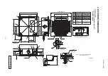
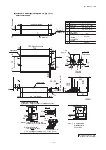
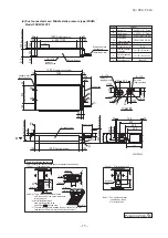
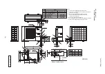
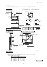
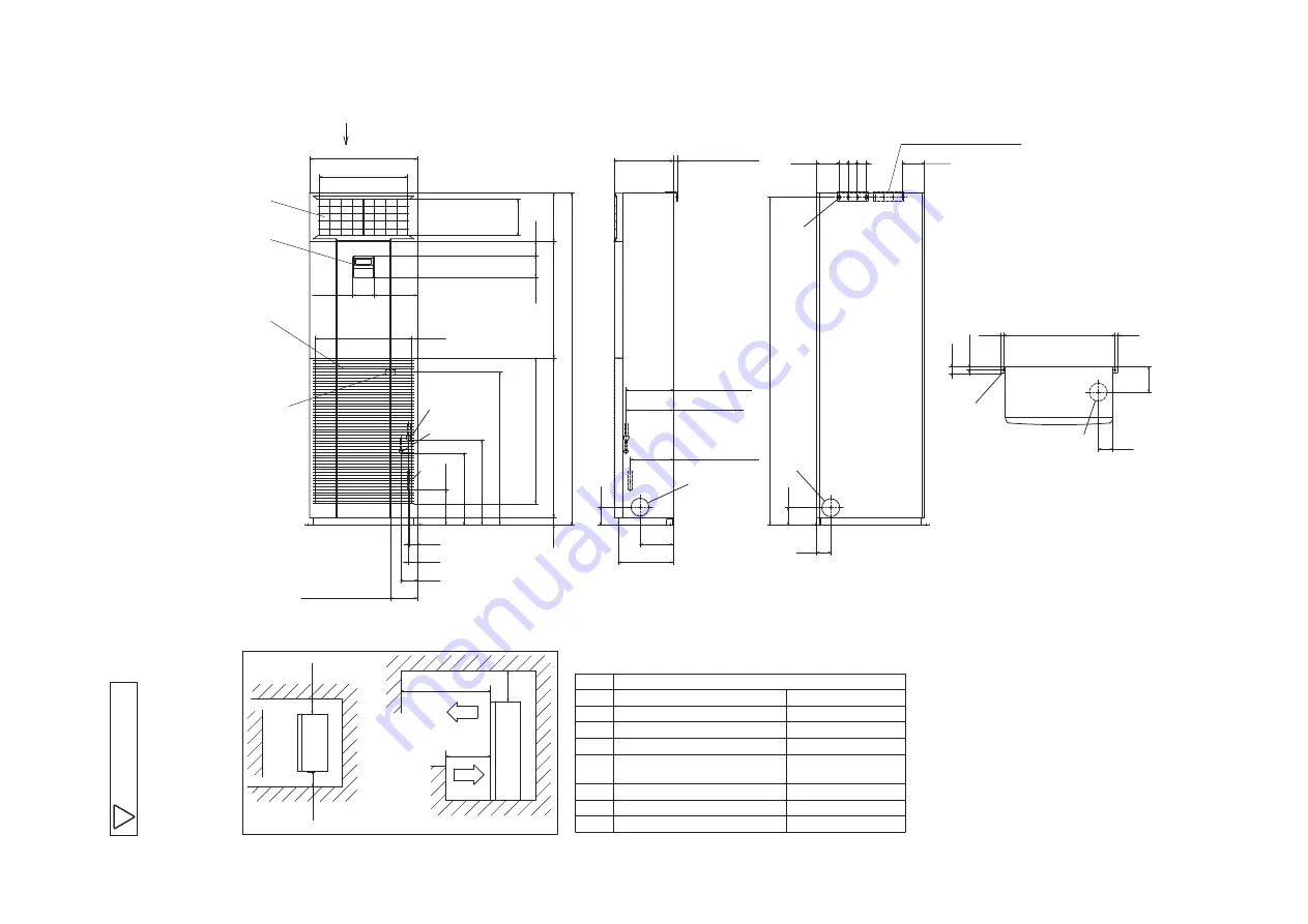
Space for installation and service
A
E
C
B
A
D
F
H
G
A
or
m
or
e
or
m
or
e
or
m
or
e
or more
or more
490
19
7.
5
80
600
240
120
18
50
65
0
27
0
537
78
95
18
27
50
50
50
185
306
48
93
40
0.
5
47
4
45
19
6
89
0
40
12
0
85
2
150
98
329
600
1000
10
0
50
Air return
Air supply
125
(
Range that
262
(
Gas
)
264
(
Liquid)
238.5
(
Drain
)
125
H can be installed left
Terminal block
(
Power source
)
Air supply
81
2.
5
50
φ
100
(
Knock out
)
Hole on wall for rear piping
4-7
×
25
(
Slot
)
Fresh air intake
(
Both left and right
)
Hole on wall for side piping
/
M8
(
2 places
)
φ
100
(
Knock out
)
φ
100
(
Resin cap having
)
VP20
(
I.D.20,O.D.26
)
Fall prevention metal fittings
Metal fittings to fix to floor face
Hole on wall for bottom piping
Drain piping
Liquid piping
Gas piping
H
G
F
E
D
C
B
A
Content
Symbol
φ
9.52
(
3
/
8"
)(
Flare
)
φ
15.88
(
5
/
8"
)(
Flare
)
14
3
82
15
622.5
15
17
.5
35
25
-
50
Unit:mm
(
Center of
terminal block
)
(
Ce
nt
er
of
te
rm
in
al
bl
oc
k
)
can be adjusted
)
Remote
control
Air return
grille
Note
(
1
)
The model name label is attached on the
left lower side panel inside the air return grille.
(e) Floor standing type (FDF)
Model FDF100VD2
A
P
G
A
0
0
0
Z
8
0
1

