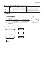
-
203
-
'16 • PAC-T-240
When a heat exchanger sensor 1 wire disconnection is detected while
operation is stopped. (If a temperature of –28ºC or lower is detected for
15 seconds, it is judged that the wire is disconnected.)
(Not displayed during operation.)
When a room temperature sensor wire disconnection is detected while
operation is stopped. (If a temperature of –45ºC or lower is detected for
15 seconds, it is judged that the wire is disconnected.)
(Not displayed during operation.)
• Broken heat exchanger sensor
1 wire, poor connector
connection
• Indoor control PCB is faulty
• Broken room temperature
sensor wire, poor connector
connection
• Indoor control PCB is faulty
Heat exchanger
sensor 1 error
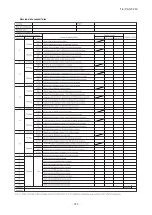
When this air-conditioner performs an emergency stop, the reason why the emergency stop occurred is displayed by the flashing
of display lights. If the air-conditioner is operated using the remote control 3 minutes or more after the emergency stop, the
trouble display stops and the air-conditioner resumes operation.
(1)
Room
temperature
sensor error
When conditions for turning the indoor unit’s fan motor on exist during air-
conditione roperation, an indoor unit fan motor speed of 300 min
-1
or lower
is measured for 30 seconds or longer. (The air-conditioner stops.)
• Defective fan motor, poor
connector connection
Indoor fan
motor error
–55ºC or lower is detected for 5 seconds continuously 3 times within
40 minutes after initial detection of this anomalous temperature.
Or –55ºC or lower is detected for within 20 seconds after power ON.
–55ºC or lower is detected for 5 seconds continuously 3 times within
40 minutes after initial detection of this anomalous sensor.
Or –55ºC or lower is detected for within 20 seconds after power ON.
• Outdoor heat exchanger
temperature sensor
• Outdoor control PCB is faulty
Outdoor heat
exchanger
temperature
sensor anomaly
–25ºC or lower is detected for 5 seconds continuously 3 times within
40 minutes after initial detection of this anomalous sensor.
• Discharge pipe temperature
sensor
• Outdoor control PCB
Discharge pipe
temperature
sensor anomaly
If the output current of inveter exceeds the specifications, it makes the
compressor stopping.
• Outdoor control PCB is faulty
• Defective compressor
•
Installation, operation status
Current cut
If compressor fails to startup for 42 times.
If the power transistor primary current exceeds the setting value for 3
seconds, the compressor stops.
• Defective compressor
• Outdoor control PCB is faulty
Compressor
startup failure
When discharge pipe temperature anomaly is detected 2 times within 60
minutes is compressor stop.
•
Installation, operation status
• Discharge pipe
temperature sensor
•
Outdoor control PCB is faulty
Discharge pipe
temperature
error
When there is no signal between the indoor control PCB and outdoor control
PCB for 10 seconds or longer (when the power is turned on), or when there
is no signal for 7 minute 35 seconds or longer (during operation)
(the compressor is stopped).
• Defective power source,
Broken signal wire, defective
indoor/outdoor control PCB
Error of signal
transmission
If it fails again to detect the rotor position after shifting to the
compressor rotor position detection operation, the compressor stops.
• Defective compressor
• Operation status
• Installation status
Compressor
rotor lock
error
When actual rotation speed of outdoor fan motor drops to 75min
-1
or
lower for 30 minutes continuously, the compressor and the outdoor fan
motor stop. After 3-minutes delay, it starts again automatically, but if this
anomaly occurs 3 times within 60 minutes after the initial detection.
• Defective fan motor
• Outdoor control PCB is faulty
Outdoor fan
motor anomaly
Indoor unit display panel
Description
of trouble
Cause
Display (flashing) condition
When the current safe control has operated at the compressor speed of
20 rps or under.
• Overload operation
• Overcharge
• Compressor locking
Current safe
stop
The wired remote control wire Y is open. The wired remote
control wires X and Y are reversely connected. Noise is penetrating
the wired remote control lines. The wired remote control or indoor control
PCB is faulty. (The communications circuit is faulty.)
• Broken wired remote control
wire, defective indoor control
PCB
Notes (1) The air-conditioner cannot be restarted using the remote control for 3 minutes after operation stops.
(2) The wired remote control is option parts.
Error of wired
remote control
wiring
• Power transistor error
(Outdoor control PCB is faulty)
Power
transistor
anomaly
When a heat exchanger sensor 2 wire disconnection is detected while
operation is stopped. (If a temperature of –28ºC or lower is detected for
15 seconds, it is judged that the wire is disconnected.)
(Not displayed during operation.)
• Broken heat exchanger sensor
2 wire, poor connector
connection
• Indoor control PCB is faulty
Heat exchanger
sensor 2 error
When anomalous outdoor heat exchanger temperature occurs 5 times
within 60 minutes or 60
℃
or higher continues for 10 minutes, including
the compressor stop.
•
Installation, operation status
•
Outdoor heat exchanger
temperature sensor
•
Outdoor control PCB is faulty
Cooling
overload
operation
Error is displayed if the converter voltage exceeds target voltage (3 times
within 20 minutes). Remote control may be set after 3 minutes delay.
Error is displayed if the converter voltage is lower than 210V
(1-time within 5 seconds after power ON)
•
Outdoor control PCB is faulty
Active filter
voltage error
When the insufficient refrigerant amount is detected 3 times within 60
minutes.
Insufficient refri
-gerant amount or
detection of servi
-ce valve closure
ON
ON
ON
2-time
flash
4-time
flash
1-time
flash
2-time
flash
5-time
flash
6-time
flash
2-time
flash
7-time
flash
TIMER
light
3-time
flash
—
4-time
flash
ON
Keeps
flashing
ON
ON
1-time
flash
2-time
flash
6-time
flash
Keeps
flashing
Keeps
flashing
ON
ON
ON
ON
2-time
flash
ON
RUN
light
—
ON
ON
3-time
flash
ON
5-time
flash
7-time
flash
E 16
• Outdoor aie temperature
sensor
• Outdoor control PCB is faulty
Outdoor air
temperature
sensor anomaly
1-time
flash
Keeps
flashing
E 38
E 37
E 39
E 42
E 59
E 36
E 5
E 60
E 47
E 48
E 35
E 1
E 58
E 51
Wired
(2)
remote
control
display
E 57
—
—
—
(5) Self-diagnosis table

