background image

-

 213 

-

 '16 • PAC-T-240

'09•SRK-DB-087D

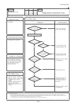
Over heat of compressor

Gas shortage, defective discharge 

pipe sensor

Error of signal transmission

Wiring error including power cable, defective indoor/

outdoor control PCB

② ③

control

② ③

① ②

69)

control

control

Summary of Contents for FDE100VNP1VG

Page 1: ...ASSETTE 4WAY TYPE FDT100VNP1VF2 CEILING SUSPENDED TYPE FDE100VNP1VG DUCT CONNECTED HIGH STATIC PRESSURE TYPE FDU100VNP1VF2 FLOOR STANDING TYPE FDF100VNP1VD2 WALL MOUNTED TYPE SRK100VNP1ZR DUCT CONNECTED LOW MIDDLE STATIC PRESSURE TYPE FDUM100VNP1VF2 Manual No 16 PAC T 240 updated April 26 2016 TECHNICAL MANUAL ...

Page 2: ...nected High static pressure type FDU 57 3 Floor standing type FDF 36 2 EXTERIOR DIMENSIONS 12 1 Indoor units 12 2 Outdoor unit 18 3 Remote control 19 3 ELECTRICAL WIRING 22 4 NOISE LEVEL 29 5 CHARACTERISTICS OF FAN 32 6 TEMPERATURE AND VELOCITY DISTRIBUTION 34 7 PIPING SYSTEM 37 8 RANGE OF USAGE LIMITATIONS 38 1 Indoor units 22 2 Outdoor unit 28 1 Indoor units 29 2 Outdoor unit 31 9 2 Correction o...

Page 3: ... Auto swing control 115 118 9 Thermostat operation 116 10 Filter sign 117 117 13 Drain pump abnormalities detection 11 Compressor inching prevention control 12 Drain pump control 118 3 Dehumidifying operation 112 119 118 16 Heating overload protection 14 Operation check drain pump test run operation mode 15 Cooling dehumidifying frost protection 119 120 120 19 High ceiling control 17 Anomalous fan...

Page 4: ... 7 Cooling low outdoor temperature protective control 141 8 Heating high pressure control 142 9 Heating overload protective control 䊠 142 142 10 Heating overload protective control 䊡 143 11 Heating low outdoor temperature protective control 11 3 2 SRK series 128 130 7 Economy operation 130 6 High power operation 5 Selection of the annual cooling function 130 134 129 2 Unit ON OFF button 129 1 Oper...

Page 5: ...ilure diagnosis circuit diagram 158 159 1 List of troubles 159 2 Troubleshooting 160 12 1 2 Troubleshooting flow 202 4 Troubleshooting procedure If the air conditioner runs 12 2 SRK series 201 3 Troubleshooting procedure If the air conditioner does not run at all 201 1 Cautions 201 2 Items to check before troubleshooting 201 10 How to make sure of wireless remote control 216 11 Inspection procedur...

Page 6: ... pressure type FDU 249 5 Floor standing type FDF 251 6 Wall mounted type SRK 252 ڦ How to read the model name FDT FDE FDU FDUM FDF SRK FDC Example FDT 100 VNP1 VF2 Series code Applicable power source See the specification Product capacity Model name Ceiling cassette 4way type Ceiling suspended type Duct connected High static pressure type Duct connected Low Middle static pressure type Floor standi...

Page 7: ...eeve for fan motor compressor Electric heater W Operation control Remote control option wired RC EX1A RC E5 RCH E3 wireless RCN T 36W E Room temperature control Thermostat by electronics Operation display Safety equipments Compressor overheat protection Overcurrent protection Frost protection Serial signal error protection Indoor fan motor error protection Heating overload protection High pressure...

Page 8: ...ssor Electric heater W 0 Operation control Remote control option wired RC EX1A RC E5 RCH E3 wireless RCN E E Room temperature control Thermostat by electronics Operation display Safety equipments Compressor overheat protection Overcurrent protection Frost protection Serial signal error protection Indoor fan motor error protection Heating overload protection High pressure control Cooling overload p...

Page 9: ...temperature control Thermostat by electronics Operation display Safety equipments Compressor overheat protection Overcurrent protection Frost protection Serial signal error protection Indoor fan motor error protection Heating overload protection High pressure control Cooling overload protection Installation data Refrigerant piping size O D mm Liquid line I Uφ9 52 3 8 Pipeφ9 52 3 8 0 8 O Uφ9 52 3 8...

Page 10: ...CN KIT3 E Room temperature control Thermostat by electronics Operation display Safety equipments Compressor overheat protection Overcurrent protection Frost protection Serial signal error protection Indoor fan motor error protection Heating overload protection High pressure control Cooling overload protection Installation data Refrigerant piping size O D mm Liquid line I Uφ9 52 3 8 Pipeφ9 52 3 8 0...

Page 11: ...ompressor Electric heater W Operation control Remote control RC E5 Installed wireless RCN KIT3 E option Room temperature control Thermostat by electronics Operation display Safety equipments Compressor overheat protection Overcurrent protection Frost protection Serial signal error protection Indoor fan motor error protection Heating overload protection High pressure control Cooling overload protec...

Page 12: ...uantity Polypropylene net washable x 2 Shock vibration absorber Rubber sleeve for fan motor Rubber sleeve for fan motor compressor Electric heater Operation control Remote control Wireless Remote control Room temperature control Microcomputer thermostat Operation display RUN Green TIMER Yellow HI POWER Green 3D AUTO Green Safety equipments Compressor overheat protection Overcurrent protection Fros...

Page 13: ...ol Content φ9 52 3 8 Flare for ducting for ducting Space for installation and service Knock out Knock out G Holes for tapping screws Hole 5 φ4 Holes for tapping screws 6 φ4 Hole Decorative panel Ceiling hole size Suspension bolts pitch Suspension bolts pitch C Installed on site Drain hose piece suspension bolt Hanger plate for Control box or more Max Drain lift or less box Control 778 860 910 725 ...

Page 14: ... 13 16 PAC T 240 C1 C2 C1 C2 C2 C1 A E G F A B B D b Ceiling suspended type FDE Model FDE100VG PFA004Z027 ...

Page 15: ...units For fan units maintenance refer to page 61 b Install refrigerant pipes drain pipe and wiring so as not to cross marked area c The case that pipes are installed to upper bottom of fan unit keep space of 60mm or more to upper bottom of unit C1 Drain piping VP25 I D 25 O D 32 VP20 I D 20 O D 26 Unit mm 4 φ4 Suspension bolts pitch Air supply duct Control box Duct dimension Duct dimension 18 1368...

Page 16: ...There must not be obstacle to draw out 2 fan units For fan units maintenance refer to page 66 b Install refrigerant pipes drain pipe and wiring so as not to cross marked area c The case that pipes are installed to upper bottom of fan unit keep space of 60mm or more to upper bottom of unit C1 Drain piping VP25 I D 25 O D 32 VP20 I D 20 O D 26 Unit mm 4 φ4 Suspension bolts pitch Air supply duct Cont...

Page 17: ... 7 25 Slot Fresh air intake Both left and right Hole on wall for side piping M8 2 places φ100 Knock out φ100 Resin cap having VP20 I D 20 O D 26 Fall prevention metal fittings Metal fittings to fix to floor face Hole on wall for bottom piping Drain piping Liquid piping Gas piping H G F E D C B A Content Symbol φ9 52 3 8 Flare φ15 88 5 8 Flare 143 82 15 622 5 15 17 5 35 25 50 Unit mm Center of term...

Page 18: ...ce for installation and service when viewing from the front 768 157 48 240 6 7 322 4 214 5 214 5 883 157 10 3 262 19 43 5 64 64 55 47 53 77 47 1197 339 55 150 50 Service space Service space Service space 15 100 780 759 715 55 Installation plate Unit mm Note 1 The model name label is attached on the underside of the indoor unit Outlet for down piping Refer to the above view Terminal block 60 240 43...

Page 19: ...n front of the blower outlet must not exceed the units height 6 The model name label is attached on the service panel φ15 88 5 8 Flare Content C Pipe cable draw out hole D E Anchor bolt hole Drain discharge hole Symbol B A Service valve connection gas side M10 4 places φ20 3 places Service valve connection liquid side φ9 52 3 8 Flare F Cable draw out hole φ30 3 places Unit mm 846 60 15 2 R 2 φ15 L...

Page 20: ...ore Adapted to RoHS directive Exterior appearance Munsell color Pearl white N8 5 near equivalent PJZ000Z297 3 Remote control a Wired remote control Option parts Model RC EX1A Interface kit SC BIKN E is required to use the wired remote control SRK series only ...

Page 21: ...Upper part Lower part Lower case Sheath Upper cace Board Wiring Upper Lower X Y Sheath Upper cace Board Wiring Upper Lower Y X Tighten the screws after cutting off the thin part of screw mounting part Embedded mounting The peeling off length of sheath The peeling off length of sheath In case of pulling out from upper left In case of pulling out from upper left In case of pulling out from upper lef...

Page 22: ... 21 16 PAC T 240 b Wireless remote control Unit mm Unit mm RCN E1R Option parts Except SRK series SRK series only Standard accessory 60 17 150 60 26 167 ...

Page 23: ...8 9 10 11 12 11 12 DM RD WH 1 2 CNR WH CNW1 WH M WH WH WH WH WH WH WH WH WH WH WH 1 2 3 4 5 6 1 2 3 4 CNV2 BK CNTA BL 1 2 SW8 BL WH 1 3 CNW3 WH CNW2 WH CNWR2 WH L Drain motor Fan motor DM Louver motor Float switch LM1 4 FS Fuse F1 3 Connector CNB Z LED 2 Operation check Drain motor test run Thermistor Remote control Model capacity setting SW6 Terminal block Power source 口mark TB1 TB2 Indication la...

Page 24: ... Thi R2 Thi R3 BK BK BK BK BK BK CNTA BL 1 2 YE GN 3 BL WH 1 3 CNW3 WH F2 3 15A SW2 SW6 SW5 SW7 LED 2 LED 3 CNZ FOR HA WH 12 BK BK Connecting line between indoor unit and outdoor unit 2 1 3 Power source line Signal line XR5 Remote operation volt free contact YE GN CNI BL WH 1 4 5 6 7 L CNWR2 WH CNF1 WH RD 1 2 Fan motor Indication lamp Red Inspection Connector CNB Z LED 2 Model capacity setting SW6...

Page 25: ... 5 6 BK t BK 1 2 XR1 XR2 XR3 XR4 XR5 Remote operation 1 2 3 4 5 6 12 SW2 SW6 SW5 SW7 LED 2 LED 3 X Y 1 3 X Y t TB2 WH BK WH 8 9 10 11 12 8 9 10 11 12 CNW2 WH CNW1 WH CNB WH CNN YE CNH BK CNT BL 1 2 WH RD YE GN 3 5 CNW0 WH 1 TB1 Power circuit Operation Heating Compressor ON Inspection 3 ThC WH WH WH WH Remote control input volt free contact WH WH WH WH WH WH WH WH 3 4 5 6 7 1 2 5 6 7 2 3 4 1 YE GN ...

Page 26: ...YE t YE BK t BK 1 2 3 4 5 6 BK t BK 1 2 XR1 XR2 XR3 XR4 XR5 Remote operation input volt free contact Prepare on site 1 2 3 4 5 6 12 SW2 SW6 SW5 SW7 LED 2 LED 3 X Y 1 3 X Y t TB2 WH BK WH 8 9 10 11 12 8 9 10 11 12 CNW2 WH CNW1 WH CNB WH CNN YE CNH BK CNT BL 1 2 WH RD YE GN 3 5 CNW0 WH 1 TB1 Power circuit Operation Heating Compressor ON Inspection 3 ThC WH WH WH WH Remote control WH WH WH WH WH WH W...

Page 27: ...A TB2 Terminal block Signal line 口mark Relay for DM X4 TB1 Terminal block Power source mark Plural units Master Slave setting CNZ BK t Control PCB Power PCB BK BK t BK GR t GR 1 2 3 4 5 6 BK t BK 1 2 XR1 XR2 XR3 XR4 XR5 Remote operation input volt free contact Prepare on site 1 2 3 4 5 6 12 SW6 SW5 SW7 X Y 1 3 X Y t TB2 WH BK RD 1 2 3 4 5 1 2 3 4 5 CNW3 RD CNW2 RD BL 2 1 3 4 5 1 2 3 4 5 CNW4 BL CN...

Page 28: ...WH BK BL Y Y G BK CNG CNE DISPLAY WIRELESS RECEIVER CNF BACK UP SW 2 8 Th21 Th22 Th1 Th3 CNY Y G CNM 5 Color marks Meaning of marks Blue Black BK Red BL RD White WH Yellow Green Y G Yellow Y Color Mark Heat exchanger sensor Humidity sensor Fan motor Room temp sensor Flap motor Th1 Th21 2 Th3 Diode stack DS Fuse F Connector CNE FMI Terminal block TB Louver motor LM1 2 SM1 Description Item Varistor ...

Page 29: ... Earth wire size mm At the connection with the duct type indoor unit FDC100VNP 5 5 䃥1 6 3 䃥1 6 MODEL NAME 22 24 MAX running current A Power cable size mm2 Power cable length m indoor outdoor wire size x number mm Earth wire size mm Power source 1 Phase 220 240V 50Hz BLOCK 2 TERMINAL BLOCK 1 TERMINAL 2 3 1 2 TO INDOOR UNIT POWER WIRES SIGNAL WIRE N M BK WH RD V W U PCB ASSY M BK MS TRANSISTOR POWER...

Page 30: ... P Hi 40 dB A at Hi 37 dB A at Me 35 dB A at Lo Measured based on JIS B 8616 Mike position Measured based on JIS B 8616 Mike position b Ceiling suspended type FDE Unit 1m 1m Mike in front below unit N60 40 50 40 50 63 125 250 500 1000 2000 4000 8000 10 20 30 10 20 30 N50 N40 N30 N20 60 60 N10 Souud Pressure Level dB standard 2 10 5 Pa Mid Octave Band Frequency Hz Model FDE100VG Noise level 48 dB A...

Page 31: ...dB standard 2 10 5 Pa Mid Octave Band Frequency Hz d Floor standing type FDF Model FDF100VD2 Noise level 54 dB A at P Hi 50 dB A at Hi 48 dB A at Me 44 dB A at Lo N60 40 50 40 50 63 125 250 500 1000 2000 4000 8000 10 20 30 10 20 30 N50 N40 N30 N20 60 60 N10 Souud Pressure Level dB standard 2 10 5 Pa Mid Octave Band Frequency Hz e Wall mounted type SRK Model SRK100ZR S Measured based on JIS C 9612 ...

Page 32: ...8000 30 40 50 60 70 80 30 40 50 60 70 80 Mid Octave Band Frequency Hz Souud Pressure Level dB standard 2 10 5 Pa N40 N50 N30 N60 N70 N80 63 125 250 500 1000 2000 4000 8000 30 40 50 60 70 80 30 40 50 60 70 80 Mid Octave Band Frequency Hz Souud Pressure Level dB standard 2 10 5 Pa 63 125 250 500 1000 2000 4000 8000 40 50 60 70 80 90 40 50 60 70 80 90 Mid Octave Band Frequency Hz Souud Pressure Level...

Page 33: ...tatic pressure Pa 0 20 40 60 80 100 120 140 160 180 200 220 10 15 20 25 30 35 40 45 Air flow m3 min External static pressure Pa Range of approvable air flow In case actual E S P correspond setting of E S P 0 20 40 60 80 100 120 140 160 180 200 220 32 33 34 35 36 38 39 40 37 Air flow m3 min External static pressure Pa SW8 4 OFF Range of use limitation Setting 80Pa 150Pa Characteristic FAN 1 Charact...

Page 34: ...x 90Pa 80Pa 70Pa 60Pa rated 50Pa 40Pa 30Pa 20Pa 10Pa Min In case actual E S P correspond to setting of E S P Hi Hi Hi Me Me Me Characteristic FAN 1 shows air flow vs External Static Pressure E S P range where settings of E S P are maximum E S P 100Pa rated E S P and minimum E S P 10Pa Characteristic FAN 2 shows air flow vs E S P curve when set fan tap is set P Hi with each setting of E S P by remo...

Page 35: ...Heating 20 CDB Note These figures represent the typical main range of temperature and velocity distribution at the center of air outlet within the published conditions In the actual installation they may differ from the typical figures under the influence of air temperature conditions ceiling height operation conditions and obstacles Cooling Air flow P Hi Heating Air flow P Hi 20 40 1 Ceiling cass...

Page 36: ...ty distribution Velocity distribution 4m 3m 2m 1m 0m 8m 7m 5m 6m 0m 1m 2m 3m 3m 2m 1m 0m 15 18 21 24 m sec m sec 4m 3m 2m 1m 0m 8m 7m 5m 6m 0m 1m 2m 3m 3m 2m 1m 0m 2 0 1 5 1 0 0 5 35 32 29 26 23 4m 3m 2m 1m 0m 8m 7m 5m 6m 0m 1m 2m 3m 3m 2m 1m 0m 2 0 1 5 1 0 0 5 4m 3m 2m 1m 0m 8m 7m 5m 6m 0m 1m 2m 3m 3m 2m 1m 0m 2 Ceiling suspended type FDE Model FDE100VG ...

Page 37: ...on Temperature distribution 18 20 22 24 1 67m 8m 28 30 32 34 36 26 38 40 42 1 67m 8m Models All model a Cooling Air flow Hi Louver position Horizontal Heating Air flow Hi Louver position Horizontal 3 Floor standing type FDF Model FDF100VD2 Cooling Air flow Hi Louver position Horizontal ...

Page 38: ... pipie φ15 88 Liquid pipe φ9 52 Service valve Flaare connecting Check joint Service valve Flaare connecting Electronic expansion valve Strainer Strainer Capillary tube Outdoor air temp sensor Muffler Compressor Discharge pipe temp sensor 4way valve TH3 TH2 Heat exchanger sensor TH1 EEV Capillary tube Heat exchanger Accumulator Muffler Accumulator Outdoor unit Cooling cycle Heating cycle Service va...

Page 39: ... 3 or less Note 1 Do not install the unit in places which 1 Flammable gas may leak 2 Carbon fiber metal particles powder etc are floating 3 Cosmetic or special sprays are used frequently 4 Exposed to oil splashes or steam e g kitchen and machine plant 5 Exposed to sea breeze e g coastal area or calcium chloride e g snow melting agent 6 Exposed to ammonia substance e g organic fertilizer 7 Matters ...

Page 40: ...mentioned above and cooling capacity may not be established under certain conditions Precaution In case of severely low temperature condition 1 Install the outdoor unit at the place where strong wind cannot blow directly into the outdoor unit 2 If there is no installation place where can prevent strong wind from directly blowing into the outdoor unit mount the flex flow adapter prepared as option ...

Page 41: ...nit Dimensional limitations Marks appearing in the drawing One way pipe length FDC100VNP 30m L H Elevation difference between indoor and outdoor unit When the outdoor unit is positioned higher 20m When the outdoor unit is positioned lower 20m H L Outdoor unit Indoor unit PJF000Z317 PJF000Z317 ...

Page 42: ... 18 8 61 10 45 8 54 10 66 8 44 11 08 8 86 11 51 8 64 7 16 7 13 7 10 7 06 7 02 9 59 8 09 10 16 8 60 10 44 8 54 10 67 8 44 11 11 8 87 11 56 8 66 7 75 7 71 7 67 7 63 7 59 9 60 8 09 10 17 8 61 10 46 8 55 10 69 8 45 11 14 8 88 11 60 8 67 8 33 8 29 8 24 8 20 8 15 9 03 8 18 9 60 8 09 10 19 8 62 10 48 8 55 10 71 8 46 11 17 8 89 11 63 8 68 8 92 8 87 8 81 8 77 8 72 9 02 8 18 9 61 8 10 10 20 8 62 10 51 8 56 ...

Page 43: ...10 25 7 72 10 55 7 58 11 14 7 98 8 24 7 05 8 61 7 53 9 26 7 35 9 83 7 82 10 13 7 69 10 42 7 55 11 01 7 96 8 08 6 99 8 47 7 48 9 14 7 31 9 71 7 79 10 00 7 66 10 29 7 52 10 87 7 93 7 85 6 90 8 23 7 40 8 84 7 23 9 37 7 70 9 67 7 58 9 96 7 45 10 54 7 87 7 62 6 82 7 98 7 32 8 54 7 14 9 03 7 61 9 33 7 50 9 62 7 38 10 21 7 81 7 39 6 73 7 74 7 24 8 24 7 05 8 70 7 53 8 99 7 42 9 29 7 31 9 89 7 75 7 16 6 65...

Page 44: ... 7 80 8 24 6 76 8 61 7 12 9 26 7 11 9 83 7 51 10 13 7 46 10 42 7 40 11 01 7 75 8 08 6 68 8 47 7 06 9 14 7 05 9 71 7 46 10 00 7 41 10 29 7 35 10 87 7 70 7 85 6 56 8 23 6 94 8 84 6 92 9 37 7 31 9 67 7 27 9 96 7 22 10 54 7 59 7 62 6 44 7 98 6 83 8 54 6 79 9 03 7 18 9 33 7 14 9 62 7 10 10 21 7 47 7 39 6 33 7 74 6 71 8 24 6 65 8 70 7 04 8 99 7 01 9 29 6 97 9 89 7 36 7 16 6 21 7 10 6 41 7 54 6 35 7 93 6...

Page 45: ...ndoor air temperture 19éWB Indoor air temperture 12éWB Indoor air temperture 15éWB Indoor air temperture 17éWB Outdoor air temperture 10éWB Outdoor air temperture 10éWB Outdoor air temperture 15éWB Outdoor air temperture 18éWB Outdoor air temperture 1éWB Outdoor air temperture 7éWB 䠷References data䠹 Capacity variation against outdoor and indoor temperature at the maximum compressor speed capacity ...

Page 46: ...btain the cooling and heating capacity Net cooling capacity 10 0 1 00 0 97 0 99 9 6 kW Example The net cooling capacity of the model FDT100VNP1VF2 with the air flow P Hi the piping length of 15m the outdoor unit located 5m lower than the indoor unit indoor wet bulb temperature at 19 0 and outdoor dry bulb temperature 35 is Net cooling total capacity of FDT100VNP1VF2 Outdoor temp 35 DB Indoor temp ...

Page 47: ...breaker is not installed it can cause electric shocks Use the circuit breaker of correct capacity Circuit breaker should be the one that disconnect all poles under over current Using the incorrect one could cause the system failure and fire Do not use any materials other than a fuse of correct capacity where a fuse should be used Connecting the circuit by wire or copper wire could cause unit failu...

Page 48: ...proper number of blow out air supply port direction from 4 way 3 way or 2 way according to the shape of the room and installation position 1 way is not available If it is necessary to change the number of air supply port prepare the covering materials sold as accessory Instruct the user not to use low fan speed when 2way or 3way air supply is used Do not use 2way air supply port under high tempera...

Page 49: ...t pipe continued Refrigerant pipe Be sure to use new pipes for the refrigerant pipes Use the flare nut attached to the product or a nut compatible with JIS B 8607 Class 2 Regarding whether existing pipes can be reused or not and the washing method refer to the instruction manual of the outdoor unit catalogue or technical data 1 In case of reuse Do not use old flare nut but use the one attached to ...

Page 50: ...connection Single Split PAC series VRF KX series Main fuse specification Electrical installation work must be performed according to the installation manual by an electrical installation service provider qualified by a power provider of the country and be executed according to the technical standards and other regulations applicable to electrical installation in the country Be sure to use an exclu...

Page 51: ... manual carefully Check if the opening size for the indoor unit is correct with the level gauge supplied in the indoor unit Check if the gap between the ceiling plane and the indoor unit is correct by inserting the level gauge into the air outlet port of the indoor unit See below drawing Adjust the installation elevation if necessary If there is a height difference beyond the design limit between ...

Page 52: ...d falling of the corner panel put the strap onto the corner panel s pin with turning the strap up 2 Then hang the strap of a corner panel onto the decorative panel s pin 3 First insert the part a of a corner panel into the part A of the decorative panel and then engage four hooks A a Pin Pin How to set the airflow direction Unplug the connector of the louver motor which you want to fix the positio...

Page 53: ...rder to protect the dust Because OA does not pass through the filter equipped on FDT unit 5 Be sure to insulate OA duct If not it may have dew condensation 6 Be sure to interlock the booster fan for OA with the fan of FDT unit by using CNT connector If not the dust trapped on the filter of FDT unit may be blown out to the room by the OA being intaken during the fan of FDT unit stopping 7 Be sure t...

Page 54: ... could cause unit failure electric shock and fire due to a short circuit Earth leakage breaker must be installed If the earth leakage breaker is not installed it can cause fire and electric shocks Use the circuit breaker of correct capacity Circuit breaker should be the one that disconnect all poles under over current Using the incorrect one could cause the system failure and fire Do not use any m...

Page 55: ...pproval of the user Areas where the indoor unit can deliver hot and cold wind sufficiently Suggest to the user to use a circulator if the ceiling height is over 3m to avoid warm air being accumulated on the ceiling Areas where there is enough space to install and service Areas where it can be drained properly Areas where drain pipe descend ing slope can be taken Areas where there is no obstruction...

Page 56: ...wn with a hose clamp There is a possibility that drain water overflows 3 Connect VP 20 prepare on site to drain hose adhesive must not be used Use commercially available rigid PVC general pipe VP 20 for drain pipe 4 Do not to make the up down bending and trap in the mid way while assum ing that the drain pipes is downhill more than 1 100 Never set up air vent 5 Insulate the drain pipe Insulate the...

Page 57: ...ition the most horizotal the most downwards return to the default setting EXAMPLE the most horizontal the most downwards return to the default setting EXAMPLE shows current setting displayed for two seconds Caution If the upper limit position number and the lower limit position number are set to the same position the louver is fixed at that position auto swing does not funtion ATTENTION If you pre...

Page 58: ...Always do it according to the instruction This model blow type a PJG012D004B CAUTION CAUTION Bef Install Confirm Unit Accessory DUCT CONNECTED HIGH STATIC PRESSURE AIR CONDITIONING OUTDOOR AIR PROCESSING FDU F UNIT INSTALLATION MANUAL Space fo Perform earth wiring surely Do not connect the earth wiring to the gas pipe water pipe lightning rod and telephone earth wiring Improper earth could cause u...

Page 59: ...n duct Air supply duct Unit Under 50 mm UNIT mm Single type Multi type FDU F A B C 45 56 786 472 135 71 71 90 650 986 472 135 100 140 112 160 1100 1720 725 180 Multi type Single type 112 160 100 140 Pipe locations UNIT mm Multi type Single type 45 90 FDU F 1100 FDU F 650 71 D004B Before installation Install correctly according to the installation manual Confirm the following points Unit type Power...

Page 60: ...tside Example drip on to the ceiling with consequential water leakage in the room If vibration damping is not conducted between the unit and the duct and between the unit and the slab vibration will be transmitted to the duct and vibration noise may occur Also vibration may be transmitted from the unit to the slab Vibration damping must be performed Duct should be at their minimum length We recomm...

Page 61: ...pipe and no harmful substances such as sulfur oxide dust or a contaminant stuck on the pipes Do not use any refrigerant other than R410A Using other refrigerant except R410A R22 etc may degrade inside refrigeration oil And air getting into refrigeration circuit may cause over pressure and resultant it may result in bursting etc Store the copper pipes indoors and seal the both end of them until the...

Page 62: ...space refer to page 58 i Remove the control box and the side panel and remove the screws marked in the circles 2 places from the unit located at the near side Control box ii Take out the fan unit located at the near side in the arrow direction Side panel Screw iii Remove the screws marked in the circles 2 places from the fan unit located at the far side Screw iv Take out the fan unit in the arrow ...

Page 63: ...than a fuse of correct capacity where a fuse should be used Connecting the circuit by wire or copper wire could cause unit failure and fire Do not install the indoor unit near the location where there is possibility of flammable gas leakages If the gas leaks and gathers around the unit it could cause fire Do not install and use the unit where corrosive gas such as sulfurous acid gas etc or flammab...

Page 64: ...olt length is over 500mm or the gap between the ceiling and roof is over 700mm apply earthquake resistant brace to the bolt In case the unit is hanged directly from the slab and is installed on the ceiling plane which has enough strength When suspension bolt length is over 1000mm apply the earthquake resistant brace to the bolt Prepare four 4 sets of suspension bolt nut and spring washer M10 on si...

Page 65: ...low outlet Blowout duct optional or marketed item Bad example of duct work Bad example of duct work For ventilation Louver to outdoor air Pipe side Pipe side Side fresh air intake hole Air vent hole Fresh air intake through the suction duct Fresh air intake through the suction duct Pipe side Air vent hole Fresh air intake through the suction duct Refrigerant pipe Single type Multi type A B 40 50 2...

Page 66: ...pplied the oil is likely to decrease the slide friction force on the threads and increase in turn the axial component force so that it could crack the flare by the stress corrosion Refrigerating machine oil may be applied to the internal surface of flare only Descending slope greater than 1 100 As wide as possible about100mm Supporting metal Descending slope greater than 1 100 Please confirm that ...

Page 67: ...space refer to page 63 iii Remove the screws marked in the circles 2 places from the fan unit located at the far side iv Take out the fan unit in the arrow direction Screw Control box i Remove the control box and the side panel and remove the screws marked in the circles 2 places from the unit located at the near side ii Take out the fan unit located at the near side in the arrow direction Side pa...

Page 68: ... DPVME DBVTF B mSF PS FMFDUSJD TIPDL Use the circuit breaker of correct capacity Circuit breaker should be the one that disconnect all poles under over current 6TJOH UIF JODPSSFDU POF DPVME DBVTF UIF TZTUFN GBJMVSF BOE mSF Do not use any materials other than a fuse of correct capacity where a fuse should be used POOFDUJOH UIF DJSDVJU CZ XJSF PS DPQQFS XJSF DPVME DBVTF VOJU GBJMVSF BOE mSF Do not i...

Page 69: ...hick for entire surface of indoor unit refrigeration pipe and drain pipe Areas where TV and radio stays away more than 1m It could cause jamming and noise Areas where any items which will be damaged by getting wet are not placed such as food table wares server or medical equipment under the unit Areas where there is no influence by the heat which cookware generates SFBT XIFSF OPU FYQPTFE UP PJM NJ...

Page 70: ...d unexpected stress to the copper pipe and then remove them BT NBZ DPNF PVU at this time but it is not abnormal 1ay attention whether the flare nut pops out BT UIF JOEPPS VOJU JT TPNFUJNFT QSFTTVSFE BLF B nBSF PO MJRVJE QJQF BOE HBT QJQF and connect the refrigeration pipes on the indoor unit Bend radius of pipe must be 4D or larger Once a pipe is bent do not readjust the bending Do not twist a pip...

Page 71: ...installation manu And insulate it to prevent from dew condensation Improper installation of drain pipe may cause damage of furniture drainage water leaked or dew condensation Upward bend not allowed Trap not allowed Submersion in water not allowed Decline the pipe lightly Insulate the drain pipe to prevent dewing Especially in room and unit Incline the drain pipe downward to the outlet 1 50 1 100 ...

Page 72: ...oating Locations where any substances that can affect the unit such as sulphide gas chloride gas acid and alkaline can occur Vehicles and ships Locations where cosmetic or special sprays are often used Locations with direct exposure of oil mist and steam such as kitchen and machine plant Locations where any machines which generate high frequency harmonics are used Locations with salty atmospheres ...

Page 73: ...conditions after getting approval from the customer Where there is no obstructions to the air flow and where the cooled and heated air can be evenly distributed A solid place where the unit or the wall will not vibrate A place where there will be enough space for servicing Where space mentioned below can be secured Where wiring and the piping work will be easy to conduct The place where receiving ...

Page 74: ...e to the flared nuts Otherwise the flared nuts may crack Connect the pipes on both liquid and gas sides Tighten the nuts to the following torque n o i t r o p n o i t c e n n o c e h t f o n o i t a l u s n I n o i t c e n n o C Indoor Do not turn Cover the indoor unit s flare connected joints after they are checked for a gas leak with an indoor unit heat insulating material and then wrap them wit...

Page 75: ...the front panel Install the air filter Install the air inlet panel Front panel Screw 5 4 3 2 1 Open the air inlet panel Remove the lid Remove the wiring clamp Connect the connecting wire securely to the terminal block 1 Connect the connection wire securely to the terminal block If the wire is not affixed completely contact will be poor and it is dangerous as the terminal block may heat up and catc...

Page 76: ...nged by using a wired remote control b FDE series Model Effective range FDE100VG 9 0m Conditions 1 Height of unit 2 4 3 0 m above floor level 2 Fan speed Hi 3 Location Free space without obstacles 4 The effective range means the horizontal distance for wind to reach the floor 5 Wind speed at the effective range 0 5 m s c FDF series Model Effective range FDF100VD2 8m Conditions 1 Fan speed Hi 2 Loc...

Page 77: ...nces Both mentions the important items to protect your health and safety so strictly follow them by any means The meanings of Marks used here are as shown on the right Accord with following items Otherwise there will be the risks of electric shock and fire caused by overheating or short circuit Install r Wiring o The insu Maximu If the p But wir outside wire co 100 2 Under Under Under Switch No SW...

Page 78: ...wer 1 Input power 2 XR6 AC220 240V DC12V DC24V Note 1 0 3mm2 2m Note 1 0 3mm2 2m Note 1 Do not use the length over 2 meter Printed circuit board Remote start stop kit 0 75mm2 0 2m Butt splice Application coverage 0 75ー1 25mm2 CNT connector local vendor model Connector Made by molex 5264 06 Terminals Made by molex 5263 T CNTA connector is installed on FDT etc Refer to the spec drawings CNTA connect...

Page 79: ...val The selectable range of capacity limit Peak cut is from 0 to 40 80 20 interval Holiday setting is available After the elapse of the set time period the current set temp will be set back to the Set back temp The setting can be done in cooling and heating mode respectively The selectable range of the set time is from 20 min to 120 min 10 min interval Set the Set back temp by 1 interval 6 Filter ...

Page 80: ... fan speed setting Valid or Invalid of Auto fan speed setting can be selected B B B B B A A A A Main indoor unit address can be set Only the Main indoor unit can change operation mode and the Sub indoor units dominated by the Main indoor unit shall follow The Main indoor unit can domain 10 indoor units at a maximum 12 Installer settings 13 RC function settings Setting display item 11 Administrator...

Page 81: ...FF SW5 2 L N Remote control Remote control Remote control control line Power source line Indoor Outdoor Power source Circuit breaker Indoor Unit Indoor Unit Master Slave 1 Slave 2 Slave 3 L1 L2 L3 N Master Slave 1 Twin type Remote control line no polarity AIR CON NO Outdoor Unit Indoor Unit Indoor Unit Outdoor Unit Indoor Unit Outdoor Unit Earth Earth Earth Earth Earth Earth Earth Earth leakage br...

Page 82: ...o 30 C 68 to 86 F Lower limit setting valid except heating automatic cooling fan dry Possible to set in the range of 18 to 26 C 62 to 79 F When you set upper and lower limit by this function control as below 1 When TEMP RANGE SET remote control function of function setting mode is INDN CHANGE factory setting During heating you cannot set the value exceeding the upper limit During operation mode ex...

Page 83: ... hours After heating is stopped or heating thermostat is off the fan perform extra operation for six hours During heating is stopped or heating thermostat is off the fan perform intermittent operation for five minutes after twenty minutes off with low airflow During heating is stopped or heating thermostat is off the fan perform intermittent operation for five minutes after five minutes off with l...

Page 84: ...lay on remote control LED on indoor circuit board Error Code of indoor unit Function of CNT connector of indoor printed circuit board CNT connector local vendor model Connector Made by molex 5264 06 Terminals Made by molex 5263T Function Output 1 Output 2 Output 3 Output 4 Input 5 Operation output there is output when unit is in operation Heating output there is output when operation MODE is HEATI...

Page 85: ... 84 16 PAC T 240 B PJZ012D077 10 3 Installation of wired remote control Option 1 Model RC EX1A eco touch REMOTE CONTROL RC EX1A INSTALLATION MANUAL ...

Page 86: ...d the Installation Manual should be given to a new owner WARNING Ask a professional contractor to carry out installation work according to the installation manual Improper installation work may result in electric shocks fire or break down Shut OFF the main power source before starting electrical work Otherwise it could result in electric shocks break down or malfunction Do not install the unit in ...

Page 87: ...ontrol to medical or communication equipment could disrupt medical activities video broadcasting or cause noise interference CAUTION Do not install the remote control at following places It could cause break down or deformation of remote control 1 Where it is exposed to direct sunlight 2 Near the equipment to generate heat 3 Where the surface is not flat Do not leave the remote control with its up...

Page 88: ... m 2 0 mm2 x 2 core 3 Remote control installation procedure Determine where to install the remote control Installation Using a switch box Installed directly on a wall Wiring direction Backward Upper center Upper left Cautions for selecting installation place 1 Installation surface must be flat and sufficiently strong R C case must not be deformed 2 Where the R C can detect room temperatures accura...

Page 89: ...n Installation procedure Dimensions Viewed from front Take care to protect the removed upper case from moisture or dust PCB side Viewed from rear To remove the upper case from the bottom cases of R C Insert the tip of flat head screwdriver or the like in the recess at the lower part of R C and twist it lightly to remove Connect wires from X and Y terminals of R C to X and Y terminals of indoor uni...

Page 90: ...om case In case of exposing wiring When the wiring is taken out from the upper center or upper left of R C Cut out the thin wall sections on the cases for the size of wire Upper center Upper left Upper case Bottom case When taking the wiring out from the upper center open a hole before separating the upper and bottom cases This will reduce risk of damaging the PCB and facilitate subsequent work Wh...

Page 91: ...or more R C Up to two units of R C can be used at the maximum for 1 indoor unit or 1 group One is main R C and the other is sub R C Operating range is different depending on the main or sub R C R C function Main Sub Run Stop setting temperature fan speed and flap direction operations High power and energy saving operations Energy saving setting R C sensor Test run menu operation Room temperature r...

Page 92: ...ems and service password for installation test run and maintenance are used The administrator password at factory default is 0000 This setting can be changed Refer to User s Manual When the administrator password is forgotten it can be initialized if the High power and the Energy saving buttons are pushed simultaneously for 5 seconds on the administrator password input screen Service password is 9...

Page 93: ... thin part of remote control lower case with a nipper or knife and grind burrs with a file etc Install the lower case to the flat wall with attached two wooden screws Connect the remote control terminal block Connect the terminal of rem with the terminal of indoor u X and Y are no polarity Wiring route is as shown in depending on the pulling ou The wiring inside the remote The sheath should be pee...

Page 94: ...onnect the terminal of remote control X Y with the terminal of indoor unit X Y X and Y are no polarity Wiring route is as shown in the right diagram depending on the pulling out direction The wiring inside the remote control case should be within 0 3mm2 recommended to 0 5mm2 The sheath should be peeled off inside the remote control case The peeling off length of each wire is as below Pulling out f...

Page 95: ...nds The indication changes to FUNCTION SET 2 Press button once and change to the TEMP RANGE indication 3 Press SET button and enter the temperature range setting mode 4 Select UPPER LIMIT or LOWER LIMIT by using button 5 Press SET button to fix 6 When UPPER LIMIT is selected valid during heating Press SET button to fix Indication example UPPER 26 C Displayed for two seconds After the fixed upper l...

Page 96: ... the indoor function 04 accordingly You can select the louver stop position in the four The louver can stop at any position In normal working indication indoor unit temperature is indicated instead of airflow Only the master remote control can be indicated Heating preparation indication should not be indicated Temperature indication is by degree C Temperature indication is by degree F ON OFF butto...

Page 97: ...5 C increase in return air temperature of indoor unit To be reset producing 1 0 C increase in return air temperature of indoor unit To be reset producing 1 0 C increase in return air temperature of indoor unit To be reset producing 1 5 C increase in return air temperature of indoor unit To be reset producing 2 0 C increase in return air temperature of indoor unit When heating thermostat is OFF fan...

Page 98: ...lect ALL UNIT the setting of the lowest number indoor unit is displayed Stop air conditioner and press SET MODE buttons at the same time for over three seconds and the FUNCTION SET will be displayed Press SET button Selecct FUNCTION remote control function or I U FUNCTION indoor unit function Operation message Function description setting description Function No Fixing button Finishing button 7 2 ...

Page 99: ...ant leaks into the room and comes into contact with an oven or other hot surface poisonous gas is produced Hang up the unit at the specified points with ropes which can support the weight in lifting for portage And to avoid jolting out of alignment be sure to hang up the unit at 4 point support An improper manner of portage such as 3 point support can cause death or serious personal injury due to ...

Page 100: ...tdoor unit blows directly to an animal or plants The outlet air can affect adversely to the plant etc Locations where vibration can be amplified and transmitted due to insufficient strength of structure Locations where vibration and operation sound generated by the outdoor unit can affect seriously on the wall or at the place near bed room Locations where an equipment affected by high harmonics is...

Page 101: ... material and fill the pipe with nitrogen gas Taping N2 Nitrogen Station valve Primary side Secondary side 0 5MPa Hand Relief valve Nitrogen gas Without nitrogen gas a large quantity of foreign matters oxidized film are created causing a critical failure from capillary tube or expansion valve clogging Brazing must be performed under a nitrogen gas flow Pipe brazing Check the following points in li...

Page 102: ...Bend a pipe to a radius as large as practical R100 R150 Do not bend a pipe repeatedly to correct its form Flare connection is used between the unit and refrigerant pipe Flare a pipe after engaging a flare nut onto it Flare dimensions for R410A are different from those for conventional R407C Although we recommend the use of flaring tools designed specifically for R410A conventional flaring tools ca...

Page 103: ... materials above the ceiling where relative humidity exceeds 70 1 Calculate a required refrigerant charge volume from the following table Formula to calculate the volume of additional refrigerant required 7 Additional refrigerant charge Additional charge volume g Main length m Factory charged volume 15 m x 60 g m 60 2 55 15 Put down the refrigerant volume calculated from the pipe length onto the c...

Page 104: ...Natural and or synth rubber wire insulation Polychloroprene rubber conductors insulation Stranded core Number of conductors One conductor of the cable is the earth conductor yellow green Section of copper wire mm2 H05RNR4G1 5 Example or 245IEC57 Electrical installation work must be performed by an electrical installation service provider qualified by a power provider of the country Electrical inst...

Page 105: ...ectional area of 5 5 mm2 for power cable of outdoor unit Clearance nstall the unit part or e terior tape as piping ation rocured locally bel attached he container n you find it as sides and ling mode In liquid phase nge liquid tions so that charge minutes pressor failure The specifications shown in the above table are for units without heaters For units with heaters refer to the installation instr...

Page 106: ... Change set temp button Displays the temperature which is set currently Tap this button to change the set temperature Change operation mode button Displays the operation mode which is selected currently Tap this button to change the operation mode Timer button Displays simplified contents of the timer which is set currently When two or more timers are set contents of the timer which will be operat...

Page 107: ...ment mode Cover AIR CON No button Display the indoor unit number connected to this remote control CHECK button This button is used at servicing TEST button This button is used during test operation Weekly timer display Displays the settings of the weekly timer Operation setting display area Displays setting temperature airflow volume operation mode and oparation message Operation check indicator l...

Page 108: ...he unit starts to operate and when this is pressed once again it stops operating Used to swing the louver Every time this button is pressed displays switch as below Sets room temperature by pressing or button Sets time when setting the time Used to cancel the TIMER SETTINGS Used to reset the microcomputer Indicates the selected airflow volume Indicates when ON TIMER is set Indicates the ON TIMER s...

Page 109: ...assword 4 digit number TOP screen Menu screen 1 Menu screen 3 Service password input Tap the Menu button on the TOP screen Main menu screen is displayed Tap the Service Maintenance on the menu screen Display the service password input screen Enter the service password 4 digit number TOP screen Menu screen 1 Menu screen 3 Service password input Service maintenance menu 1 Service maintenance menu 2 ...

Page 110: ... setting of silent mode is cancelled regardless whether the power failure compensation is effective or not a At power failure Operating stopped If it had been operating under the off timer mode sleep timer mode the state of stop is memorized Although the timer mode is cancelled at the recovery from power failure the setting of weekly timer is changed to the holiday setting for all weekdays b Opera...

Page 111: ...f stop is memorized Although the timer mode is cancelled at the recovery from power failure the setting of weekly timer is changed to the holiday setting for all weekdays b Operation mode c Airflow volume mode d Room temperature setting e Louver auto swing stop However the stop position 4 position is cancelled so that it returns to Position 1 f Remote control function items which have been set wit...

Page 112: ...ation Heating operation Room temperature detected with Thi A deg 59 56 Heating operation stopped cooling Heating OK Indoor heat exchanger temperature C b The following automatic controls are performed other than a above i Cooling or heating operation mode is judged according to the conditions of the Judgment based on Setting temperature Cooling select temperature and Indoor return air temperature ...

Page 113: ...ifying Fan Operation Functional item Thermostat ON Thermostat ON Thermostat OFF Thermostat OFF Hot start Defrost Compressor 4 way valve Outdoor unit fan Indoor unit fan Drain pump 3 2 2 Thermostat ON Thermostat OFF 2 2 Note 1 Operation Stop Turned ON OFF by the control other than the room temperature control 2 ON during the drain motor delay control 3 Drain pump ON setting may be selected with the...

Page 114: ...eekly timer Set the ON or OFF timer for a week Up to 8 patterns can be set for a day The day off setting is provided for holidays and non business days Note 1 It is necessary to set the clock to use the weekly timer vii Combination of patterns which can be set for the timer operations Note 1 Allowed Not Sleep time Sleep time Set OFF timer by hour Weekly timer Set ON timer by hour Set OFF timer by ...

Page 115: ...istor Thi R1 or R2 whichever higher detects 35 C or higher the fan operates with the set airflow volume c If the fan control at heating thermostat OFF is set at the Set airflow volume from the remote control the fan operates with the set airflow volume regardless of the thermostat ON OFF 2 Once the fan motor is changed from OFF to ON during the thermostat ON the indoor fan motor is not turned OFF ...

Page 116: ...en the air conditioner is operating SWING is displayed for 3 seconds and then the swing louver moves up and down continuously 2 To fix the swing louver at a position press one time the LOUVER button while the swing louver is moving so that four stop positions are displayed one after another per second When a desired stop position is displayed press the LOUVER button again The display stops changes...

Page 117: ...nit fan motor stops 2 Indoor fan OFF is fixed for 5 minutes After the 5 minutes the indoor fan is operated at ULo for 2 minutes In the meantime the louver is controlled at level 3 After operating at ULo for 2 minutes the indoor fan moves to the state of 1 above 4 If the thermostat is turned ON it moves to the hot start control 5 When the heating thermostat is turned OFF the remote control displays...

Page 118: ...indoor unit of which the thermostat has been turned OFF is turned OFF The same occurs also when the remote control sensor is effective 10 Filter sign As the operation time Total ON time of ON OFF switch accumulates to 180 hours 1 FILTER CLEANING is displayed on the remote control This is displayed when the unit is in trouble and under the central control regardless of ON OFF Note 1 Time setting fo...

Page 119: ...he drain pump forcibly 3 Turning the drain detection switch OFF releases the forced drain pump ON condition Normal state 1 2 Normal state Drain detection switch ON Stop 1 Indoor unit operation mode Control A Control B Compressor ON Compressor OFF Cooling Dehumidifying Heating Fan 2 Note 1 Including the stop from the cooling dehumidifying fan and heating and the anomalous stop 2 Including the Fan o...

Page 120: ... or higher and the indoor heat exchanger temperature detected with Thi R detects the compressor frequency drop start temperature A C 1 C of indoor unit fan speed is increased by 20min 1 ii If the phenomenon of 1 above is detected again after the acceleration of indoor unit fan indoor unit fan speed is increased further by 20min 1 Note 1 Indoor unit fan speed can be increased by up to 2 taps Compre...

Page 121: ...utton on the remote control displays the indoor unit address If button is pressed at the next it is displayed orderly starting from the unit of youngest No iv In case of anomaly 1 If any anomaly occurs on a unit in a group a protective function operates that unit stops with the anomalous stop but any other normal units continue to run as they are 2 Signal wiring procedure Signal wiring between ind...

Page 122: ...independent functions each other 4 In case of CnT Number CnTA Number the CnT Number and the CnTA Number become competing functions each other 5 In case of CnT Number CnTA Number the function of CnT Number supersedes that of CnTA Number 6 In case of CnT Number CnTA Number the function of CnTA Number supersedes that of CnT Number The Number above means in the table CnTA Blue 12V XR6 1 2 Note 1 CnTA ...

Page 123: ...External control set is changed from Individual Factory default to For all units all units connected in one wired remote control system can be controlled by external operation input Individual operation Factory default All units operation Local setting CnT 6 or CnTA ON OFF ON OFF Only the unit directly connected to the remote control can be operated Only the unit directly connected to the remote c...

Page 124: ...key switch is ON CnT 6 or CnTA ON Operation permission start stop operation of the unit from the wired remote control becomes available When card key switch is OFF CnT 6 or CnTA OFF Operation prohibition the unit stops operation in conjunction with OFF signal and start stop operation of the unit from the wired remote control becomes not available 2 In case that Operation permission prohibition mod...

Page 125: ...e input is set for the indoor unit function If the external input is changed OPEN CLOSE operation modes are inverted Cooling Heating or Heating Cooling Operation Operation Operation Stop Stop Stop Stop Operation prohibition Operation prohibition Operation prohibition Operation prohibition Operation prohibition Operation prohibition Operation permission Operation permission Operation permission Ope...

Page 126: ...r of revolutions of indoor unit fan speed is increased by 10min 1 ii If the indoor unit heat exchanger temperature drops below 37 C at next sampling present number of revolutions of indoor unit fan speed is reduced by 10min 1 c Ending conditions Indoor fan speed is reduced to the setting airflow volume when the compressor OFF is established and at 30 minutes after the start of heating operation 25...

Page 127: ... EX1A only Setting temperature Ts is changed according to outdoor temperature This control is valid with cooling and heating mode NOT auto mode a Operate 5 minutes forcedly b Setting temperature is adjusted every 10 minutes i Cooling mode Ts outdoor temperature offset value ii Heating mode Ts outdoor temperature offset value c If the return air temperature lower than 18 C or return air temperature...

Page 128: ...the maximum capacity Set the Start time the End time and the capacity limit Peak cut 4 operation patterns per day can be set at maximum The setting time can be changed by 5 minutes interval The selectable range of capacity limit Peak cut is from 0 to 40 80 20 interval Holiday setting is available ...

Page 129: ... function Switch for resetting microcomputer This button sets WEEKLY TIMER This button changes the HIGH POWER ECONOMY operation This button changes the air flow left right direction This buttion changes the SILENT operation This button selects OFF TIMER operation This button switches the WEEKLY TIMER to ON OFF Each time the button is pressed the fan speed changes This button sets 3D AUTO operation...

Page 130: ... the cover b ࠉSetting an indoor unit i Turn off the power source and turn it on after 1 minute ii Point the wireless remote control that was set according to the procedure described on the left side at the indoor unit and send a signal by pressing the ACL switch on the wireless remote control Since the signal is sent in about 6 seconds after theACL switch is pressed point the wireless remote contr...

Page 131: ...n HIGH POWER operation will start from the set time d When the following operation are set HIGH POWER operation will be cancelled When the HI POWER ECONO button is pressed again When the operation mode is changed When it has been 15 minutes since HIGH POWER operation has started When the 3D AUTO botton is pressed When the SILENT botton is pressed When the NIGHT SETBACK botton is pressed e Not oper...

Page 132: ...ed Louver stopped Swing When the operation is retrieved from CLEAN or ALLERGEN CLEAR operation b When the following operation are set ECONOMY operation will be canceled When the HI POWER ECONO button is pressed again When the operation mode is changed DRY to FAN c Not operable while the air conditioner is OFF d The setting temperature is adjusted according to the following table at the start of op...

Page 133: ...ting i ii Cooling Air flow selection Operation mode AUTO Heating Indoor temp Setting temp 5 C Indoor temp Setting temp 5 C Setting temp Indoor temp 5 C Setting temp Indoor temp 5 C HIGH POWER AUTO HI HI MED MED ULO ULO LO LO HIGH POWER AUTO Flap Louver Cooling Up down swing Heating Wide Fixed Center Fixed Flap Louver Cooling Heating Left right swing Horizontal blowing Fixed Slant forwardl blowing ...

Page 134: ...idifying operation 09 SRK DB 087D b Sleep timer operation 10 Timer operation a Comfortable timer setting ON timer c OFF timer operation 13 Installation location setting a Setting i If the air conditioning unit is running press the ON OFF button to stop ii Press the AIR FLOW U D UP DOWN button and the AIR FLOW L R LEFT RIGHT button together for 5 seconds or more iii Setting the air conditioning ins...

Page 135: ...tion Left louver Right louver Stops at this position for 5 seconds Activating both up down air swing and left right air swing at the same time results in a multi directional air flow However if the fan speed setting is HI and room temperature is 19 or higher this control is not executed Up down air scroll In COOL DRY and FAN operation In HEAT operation fan speed i iv ii iii b Sleep timer operation...

Page 136: ...operation a Determination of operation mode Heating Dehumidifying Cooling Indoor air temperature C Outdoor air temperature C Signals of wireless remote control Display 6 5 4 3 2 1 0 1 2 3 4 5 6 Setting temperature Cooling Dehumidifying Heating A When both the indoor and the outdoor air temperatures are in the range A cooling or heating is switched depending on the difference between the setting te...

Page 137: ...r temperatures are in the range A cooling or heating is switched depending on the difference between the setting temperature and the indoor air temperature When the operation mode has been judged following the change of setting temperature with the remote control the hourly judgment of operation mode is cancelled b i ii iii c d 27 5 25 5 18 0 18 30 AUTO MED HI LO 15 77rps 15 77rps 15 62rps 15 50rp...

Page 138: ...nd direction is set at other than the vertical swing the flaps change to the horizontal position b When the horizontal wind direction is set at other than the horizontal swing the louver changes to the vertical po sition 8 09 SRK DB 087D b Frost prevention control i Operating conditions ii Detail of anti frost operation iii Reset conditions Indoor heat exchanger temperature ºC 2 5 5 8 0 rps Lower ...

Page 139: ...a fixed speed i When the outdoor air temperature is higher than 11 C the compressor runs at 2nd speed for 30 seconds after the compressor ON ii When the outdoor air temperature is lower than 11 C the compressor runs at 1st speed for 30 seconds after the compressor ON 11 4 Operation control function by the outdoor control Unit rps 1st speed 2nd speed 3rd speed 4th speed 5th speed 6th speed 7th spee...

Page 140: ... Upper limit 3rd speed 3 Reset conditions When either of the following conditions is satisfied a The outdoor air temperature TH2 is 24ºC or higher and fan speed is 3rd speed b The compressor command speed is 0 rps 4 Outdoor unit fan speed and fan motor speed ii Heating 1 Operating conditions When the outdoor air temperature TH2 is 3ºC or lower continues for 30 seconds while the compressor command ...

Page 141: ...nsor temperature and the outdoor heat exchanger sensor temperature TH2 TH1 The outdoor air temperature 2ºC 7ºC or higher 15ºC The outdoor air temperature 2ºC 4 15 The outdoor air temperature 7ºC or higher The outdoor air temperature 15ºC 5ºC or higher 20 20 15 10 5 0 5 10 15 10 5 0 Outdoor air temperature Outdoor heat exchanger temperature Defrost operation start D efrost operation start tem perat...

Page 142: ...and speed is other than 0 rps Outdoor air temperature TH2 A B C TH2 32ºC 53 58 60 TH2 31ºC 51 53 56 b Detail of operation i The lower limit of the compressor command speed is set to 40 A rps and even if the speed becomes lower than 40 A rps the speed is kept to 40 A rps However when the thermo OFF the speed is reduced to 0 rps ii The upper limit of the compressor command speed is set to 50 65 rps ...

Page 143: ...Detail of operation 10 Heating low outdoor temperature protective control 8 6 4 6 Lower limit 45 rps Lower limit 35 rps Normal operation Outdoor air temperature C Outdoor air temperature C 11 H lower 4 11 13 16 17 OFF Upper limit 35rps Lower limit 30rps Upper limit 65rps Lower limit 25rps H 10 Heating overload protective control Ⅱ a Starting condition When the indoor heat exchanger temperature Thi...

Page 144: ...harge pipe temperature drops and the time delay of 3 minutes is over the unit starts again within 1 hour but there is no start at the third time 13 Current safe a Purpose Current is controlled not to exceed the upper limit of the setting operation current b Detail of operation Input current to the converter is monitored with the current sensor fixed on the printed circuit board of the outdoor unit...

Page 145: ... compressor has been stopped it will be restarted after the compressor start delay if a serial signal can be received again from the indoor control 17 Rotor lock If the motor for the compressor does not turn after it has been started it is determined that a compressor lock has occurred and the compressor is stopped 18 Refrigeration cycle system protection a Starting conditions i When S minutes hav...

Page 146: ...it is not detected Discharge pipe temperature sensor 25 C or lower 21 Base heater ON OFF output control Option a Base heater ON conditions When all of following conditions are met the base heater is turned ON i Outdoor air temperature detected with Tho A is 3ºC or lower ii In the heating mode iii When the compressor is turned ON b Base heater OFF conditions When either one of following conditions ...

Page 147: ...control PCB on the way of power source Replacement Fuse Blown fuse 1 time flash Keeps flashing Indoor heat exchanger tempera ture thermistor Defective indoor heat exchanger temperature thermistor defective element broken wire short circuit Poor contact of temperature thermistor connector Replacement repair of temperature thermistor 176 Indoor control PCB Defective indoor control PCB Defective temp...

Page 148: ... Replacement of PCB 192 193 Installation operation status Service valve closing operation Repair Stays OFF Keeps flashing Outdoor control PCB Over voltage Repair PCB replacement 194 Defective active filter Stays OFF Keeps flashing Fan motor Defective fan motor Replacement 195 Outdoor control PCB Defective outdoor control PCB Stays OFF Keeps flashing Power transistor error outdoor control PCB Power...

Page 149: ...inuously after initial communication was established Excessive number of connected indoor units by controlling with one remote control Whenever excessively connected indoor units is detected after power ON Return air temperature thermistor anomaly 50 C or lower is detected for 5 seconds continuously within 60 minutes after initial detection of this anomalous temperature Indoor heat exchanger tempe...

Page 150: ...oltage circuits and refrigeration cycle judge it according to ordinary inspection methods b Instruction of how to replace indoor control PCB ٨ Read the SAFETY PRECAUTIONS carefully first of all and then strictly follow it during the replacement in order to protect yourself ٨ The precautionary items mentioned below are distinguished into two levels WARNING and CAUTION Both mentions the important it...

Page 151: ...n the PCB and connect it d Control PCB Parts mounting are different by the kind of PCB item switch Address SW2 OFF ON Content of control Plural indoor units control by 1 remote control Test run SW7 1 Normal Operation check drain motor test run SW6 ON 1 2 3 4 SW6 1 2 3 4 100V ON ON OFF ON Part number SW2 Blue Address setting CNI Blue Float SW CNH Black Thermistor Return air CNB White Remote control...

Page 152: ...rminal block CNW0 White Terminal block Part number CNW3 White Terminal block CNM1 White Fan motor1 CNW1 White Control PCB CNW0 White Terminal block CNM2 Black Fan motor2 CNWR White Reactor Model FDUM PSB012D992 PSB012D993 This PCB is a general PCB Replace the PCB according to this instruction i Replace the PCB Unscrew terminal of the wiring yellow green connected to Terminal block CNWO from the bo...

Page 153: ...the board such that it will notpinch any of the wires Reconnect the wirings to the PCB Wiring connector color should match with the color of connector of the PCB Screw back the terminal Arrow A of the E2 wiring that was removed in 1 ii Power PCB Parts mounting are different by the kind of PCB Part number CNW3 White Terminal block CNM1 White Fan motor1 CNW1 White Control PCB CNW0 White Terminal blo...

Page 154: ...ration check drain motor test run SW6 1 2 3 4 100V ON ON OFF ON SW6 ON 1 2 3 4 1 Control PCB Replace and set up the PCB according to this instruction PSB012D976D a Set to an appropriate address and function using switch on PCB Select the same setting with the removed PCB b Set to an appropriate capacity using the model selector switch SW6 Select the same capacity with the PCB removed from the unit...

Page 155: ... 154 16 PAC T 240 4GRNCEG VJG 2 C D E F G Part number 3 2 Power PCB Part number 3 PSB012D953G ...

Page 156: ...Powerful mode Valid Reserved Keep OFF Test run Drain motor Normal Test run Valid Invalid Normal Model selection As per model See table 1 Remarks Address No setting at plural indoor units control by 1 R C 0 F Switches Description Default setting Table 1 Indoor unit model selection with SW6 1 SW6 4 Note 1 SW8 FDT FDE FDU FDUM only 100V ON ON OFF ON SW6 4 SW6 1 Switches SW6 2 SW6 3 Default setting SW...

Page 157: ...ture Current Target Super Heat Super Heat Discharge Pipe Super Heat Protection State No of The Compressor Outdoor Unit Fan Speed 63H1 On Off Defrost Control On Off Total Running Hours of The Compressor Pulse of The Outdoor Unit Expansion Valve EEVC Pulse of The Outdoor Unit Expansion Valve EEVH ٨Details of Compressor protection status No 33 No Contents of display 0 Normal 1 Discharge pipe temperat...

Page 158: ...Normal 1 Discharge pipe temperature protection control 2 Discharge pipe temperature anomaly 3 Current safe control of inverter primary current 4 High pressure protection control 5 High pressure anomaly 6 Low pressure protection control 8 Anti frost prevention control 9 Current cut 13 Spare 15 Current safe control of inverter secondary current 16 Stop by compressor rotor lock 17 Stop by compressor ...

Page 159: ...r Remove the fasten terminal and test output voltage Inspection of outdoor fan motor See page195 Check point of outdoor unit Color Color symbol RD Mark Yellow Green Y G Black BK Blue BL Yellow YE White WH Red Display Voltage range Voltage check in PCB The normal range is as follows DC280V DC230V DC310V DC220V DC218V DC222V DC213V DC212V DC214V DC215V DC214V DC216V DC225V DC224V DC226V DC 2 5V DC 2...

Page 160: ...erature thermistor anomaly 176 E7 Return air temperature thermistor anomaly 177 E8 Heating overload operation 178 E9 Drain trouble FDT FDU FDUM series 179 E10 Excessive number of connected indoor units more than 17 units by controlling with one remote control 180 E11 Address setting error of indoor units 181 E16 Indoor fan motor anomaly 182 E19 Indoor unit operation check 183 E20 Indoor fan motor ...

Page 161: ...r other respective parts NO YES YES NO YES YES YES NO NO Is the compressor operating NO YES NO Note 1 Outdoor 35 C Indoor 27 C 1 WAIT It is normal This unit is designed to start in the soft start mode by detecting the under dome temperature of compressor when it restart after power reset It is necessary to replace to higher capacity one or to install additional unit Compressor refrigerant oil prot...

Page 162: ... designed to start in the soft start mode by detecting the under dome temperature of compressor when it restart after power reset It is necessary to replace to higher capacity one or to install additional unit Compressor refrigerant oil protection control at starting is activated Compressor may be stopped by the error detection control For the contents of control refer to anomalous stop control by...

Page 163: ...left for long time without power source the insulation resistance may drop to a few MΩ because of refrigerant migrated in the compressor When the earth breaker is activated at lower insulation resistance check the following points Check if the earth leakage breaker is conformed to higher harmonic regulation or not Since the unit is equipped with inverter it is necessary to use components conformed...

Page 164: ...mitting to wall and etc by fixing pipes on the wall or wrapping rubber cushion around the pipe which goes through the hole in the wall or applying other appropriate means Strength of ceiling wall floor etc may be insufficient Review the installing position or reinforce it Check for leaning of installed unit or anomalous mounting of fan louver or motor and specify the contacting point and correct i...

Page 165: ... particularly during cooling or defrosting in the heating mode It is normal The noise vibration occurs when the refrigerant starts or stops flowing It is normal When the defrost operation starts or stops during heating the refrigerant flow is reversed due to switching 4 way valve This causes a large change in pressure which produces a blowing sound It may accompany also the hissing sounds as menti...

Page 166: ...ary to recover refrigerant vacuum dry and recharge refrigerant Since there could be many causes of noise vibration the above do not cover all In such case check the conditions when where how the noise vibration occurs according to following check point Indoor outdoor unit Cooling heating fan mode Startup stop during operation Operating condition Indoor outdoor temperatures pressure Time it occurre...

Page 167: ...n Is LM locked Check at the indoor unit side LM louver motor Is the louver operable with the remote control YES NO Does the louver operate at the power on YES NO YES NO Operate after waiting for more than 1 minute Repair wiring Defective indoor control PCB Replace Replace LM Normal Adjust LM lever and then check again 2 Error detection method 3 Condition of error displayed 4 Presumable cause Defec...

Page 168: ...2 Is AC220 240V detected between and 2 N on the terminal block of outdoor unit YES YES Is JX1 open YES Is the check of resistance between of CNW0 OK NO Is the checked result of resistance of FM LM etc OK NO YES YES Misconnection or breakage of connecting wires Replace fase Defective outdoor control PCB Defective indoor control or power PCB Replace Replace FM LM etc Replace fuse Defective indoor po...

Page 169: ...uited Is DC180V between of CNW2 Disconnect remote control wires NO Is DC15V or higher detected between X Y of indoor unit terminal block YES YES YES YES NO NO NO 1 Note 1 FDF series CNW3 Correct Replace wires Replace remote control Defective indoor power PCB Replace Defective indoor control PCB Replace 2 Error detection method 3 Condition of error displayed 4 Presumable cause Remote control wire b...

Page 170: ...wer source reset NO YES YES NO NO NO NO NO YES YES YES Set one remote control for Master and the other for Slave Set SW1 on remote control PCB at Master Set address again SW2 on indoor control PCB Separate remote control wires from high voltage wires Defective indoor control PCB Replace Defective remote control Change 2 Error detection method Communication between indoor unit and remote control is...

Page 171: ...above 4 Presumable cause Improper setting Surrounding environment Defective remote control communication circuit Faulty indoor control or power PCB Faulty outdoor control PCB Note If any error is detected 30 minutes after displaying WAIT on the remote control the display changes to INSPECT I U NO NO NO NO NO Are more than 3 units of remote control connected Does remote control display Slave YES Do...

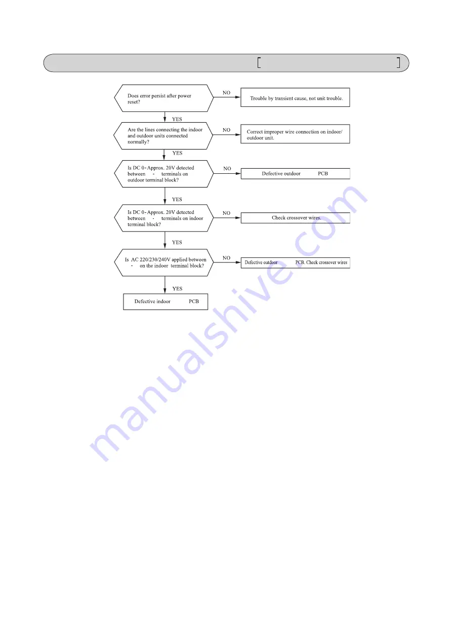
Page 172: ... YES YES YES YES Defective outdoor control PCB Replace Defective indoor control PCB Replace Replace indoor control PCB Correct connection wires between indoor and outdoor units Defective outdoor control PCB Replace Defective connection wire broken wire Noise Defective indoor control PCB Replace 2 Error detection method 3 Condition of error displayed 4 Presumable cause Blown fuse Faulty outdoor con...

Page 173: ...measure YES YES Replace the outdoor control PCB NO Replace the reactor NO Aren t there cracks or burning on the power ransistor module or diode stack Isn t reactor the anomalous From previous page Replace fuse 2 Error detection method 3 Condition of error displayed 4 Presumable cause Blown fuse Faulty outdoor control PCB Faulty reactor Note Error code Remote control LED Green Red Indoor Stays OFF ...

Page 174: ...e indoor and the outdoor units Is approx DC20V detected between 2 N on the outdoor unit terminal block NO Is approx DC20V detected between on the indoor unit terminal block NO YES NO YES YES YES Replace fuse Short circuit on remote control wire Defective remote control Correct wires Defective outdoor control PCB Replace Defective connection wire Broken wire Noise Defective indoor control PCB Repla...

Page 175: ... by noise Check peripheral environment Defective indoor control PCB Replace Defective remote control Replace 2 Error detection method When normal communication between the remote control and the indoor unit is interrupted for more than 2 minutes Detectable only with the remote control 3 Condition of error displayed Same as above 4 Presumable cause Defective communication circuit between remote con...

Page 176: ...te 2 Check for faulty connection or breakage of signal wires between indoor outdoor units YES NO YES NO Repair signal wires Repair signal wires Defective outdoor control PCB Defective network communication circuit Replace Unit is normal Malfunction by temporary noise etc 2 Error detection method When normal communication between indoor and outdoor unit is interrupted for more than 2 minutes 3 Cond...

Page 177: ... indoor control PCB Replace Defective indoor unit heat exchanger temperature thermistor input circuit 2 Error detection method Anomalously low temperature or high temperature resistance is detected on the indoor heat exchanger thermistor Thi R1 R2 or R3 3 Condition of error displayed When the temperature thermistor detects 50 C or lower for 5 seconds continuously the compressor stops After 3 minut...

Page 178: ...stor Replace Defective indoor control PCB Replace Defective return air temperature thermistor input circuit 2 Error detection method Anomalously low temperature or high temperature resistance is detected by indoor return air temperature thermistor Thi A 3 Condition of error displayed When the temperature thermistor detects 50 C or lower for 5 seconds continuously the compressor stops After 3 minut...

Page 179: ...ES NO YES NO Error stop Reset Indoor heat exchanger temperature C 56 63 For the characteristics of indoor heat exchanger temperature refer to E6 Wash Defective indoor heat exchanger temperature thermistor connector Correct Defective indoor heat exchanger temperature thermistor Check refrigerant system Adjust 2 Error detection method Indoor heat exchanger temperature thermistor Thi R1 R2 R3 3 Condi...

Page 180: ...he drain pipe slop OK NO YES NO YES NO Check float switch Defective indoor control PCB Replace Defective indoor control PCB Replace Check option equipment Correct setting to Humidifier drain motor interlock Defective indoor control PCB Replace Check wiring of drain motor Correct Check drain motor 2 Error detection method Float switch is activated 3 Condition of error displayed If the float switch ...

Page 181: ...en t more than 17 indoor units connected to one remote control NO YES Defective remote control Replace Reduce to 16 or less units 2 Error detection method When it detects more than 17 of indoor units connected to one remote control 3 Condition of error displayed Same as above 4 Presumable cause Excessive number of indoor units connected Defective remote control Note Error code Remote control LED G...

Page 182: ...2 Error detection method Indoor unit address has been set using the Indoor unit address set function of remote control 3 Condition of error displayed Same as above 4 Presumable cause Wrong address setting method It cannot set addresses from the remote control Note Is Indoor unit address set function of remote control used E11 occurs YES Error code Remote control LED Green Red Indoor Content IU IU ...

Page 183: ... If the error persists after replacing the fan motor replace the indoor control PCB Malfunction by temporary noise 2 Error detection method Detected by rotation speed of indoor fan motor 3 Condition of error displayed When actual rotation speed of indoor fan motor drops to lower than 200min 1 for 30 seconds continuously the compressor and the indoor fan motor stop After 2 seconds it starts again a...

Page 184: ...curs when the power ON NO YES Defective indoor control PCB Defective SW7 Replace Turn SW7 1 on the indoor control PCB OFF and reset the power 2 Error detection method After indoor operation check when the communication between indoor and outdoor unit is established and SW7 1 is still kept ON 3 Condition of error displayed Same as above 4 Presumable cause Mistake in SW7 1 setting Due to forgetting ...

Page 185: ...wer PCB Replace fan motor If the error persists after replacing the fan motor replace the indoor control PCB Malfunction by temporary noise 2 Error detection method Detected by rotation speed of indoor fan motor 3 Condition of error displayed When the actual fan rotation speed does not reach to the speed of required speed 50 FDU 500 min 1 after 2 minutes have been elapsed since the fan motor rotat...

Page 186: ...trol PCB Replace indoor control PCB 2 Error detection method Panel switch PS has detected Open for more than 1 second 3 Condition of error displayed Same as above 4 Presumable cause Defective panel switch Disconnection of wiring Defective indoor control PCB Note Does matter improve if panel switch is turned ON forcibly after resetting error Is grill opened NO YES NO YES YES Are connectors at right...

Page 187: ... but if this error occurs again within 60 minutes after the initial detection 4 Presumable cause Faulty connection of remote control temperature thermistor Defective remote control temperature thermistor Defective remote control PCB Note After 10 seconds has passed since remote control thermistor was switched from valid to invalid E28 will not be displayed even if the thermistor harness is disconn...

Page 188: ...amount Recharge refrigerant by weighing proper amount on a scale 2 Error detection method Anomalous stop Reset 53 51 60 56 Outdoor heat exchanger temperature C Note 1 Values in are appli cable when outdoor temperature TH2 is lower than 31 C 3 Condition of error displayed When anomalous outdoor heat exchanger temperature occurs 5 times within 60 minutes or 60 56 C or higher continues for 10 minutes...

Page 189: ...e refrigerant by weighing proper amount on a scale Control operation check Defective outdoor control PCB Replace Check unit side Isn t filter clogged Are adequate indoor outdoor unit installation spaces Isn t there any short circuit of air Isn t there any fouling clogging on indoor heat exchanger 2 Error detection method For the error detection method refer to the protective control by controlling...

Page 190: ...utdoor control PCB Replace Defective outdoor heat exchanger temperature sensor input circuit 2 Error detection method Detection of anomalously low temperature resistance on the outdoor heat exchanger temperature sensor 3 Condition of error displayed When the temperature sensor detects 55 C or lower for 20 seconds continuously within 2 minutes to 2 minutes 20 seconds after the compressor ON the com...

Page 191: ...Replace Defective outdoor air temperature sensor input circuit 2 Error detection method Detection of anomalously low temperature resistance on outdoor air temperature sensor 3 Condition of error displayed When the temperature sensor detects 55 C or lower for 5 seconds continuously within 2 minutes to 2 minutes 20 seconds after the compressor ON the compressor stops After 3 minutes delay the compre...

Page 192: ...nsor Replace Defective outdoor control PCB Replace Defective temperature sensor input circuit 2 Error detection method Detection of anomalously low temperature resistance on the discharge pipe temperature sensor 3 Condition of error displayed When the temperature sensor detects 25 C or lower for 5 seconds continuously within 10 minutes to 10 minutes 20 seconds after the compressor ON the compresso...

Page 193: ...al increase of high pressure and or test run several times restarting may recover it because liquid refrigerant migrated in the compresser is discharged from the compressor Replace compressor 2 Error detection method In order to prevent from overcurrent of inverter if the current exceeds the specifications it makes the compressor stopping 3 Condition of error displayed If the output current of inv...

Page 194: ...or run Are the service valves fully opened Is the filter clogged Is there any liquid flooding Is the superheat within normal range Is there any anoumalous sound on the compressor YES From previous page YES Defective outdoor control PCB Replace Defective outdoor control PCB Replace 2 Error detection method In order to prevent from overcurrent of inverter if the current exceeds the specifications it...

Page 195: ... matter like dust fouling etc Defective outdoor control PCB Replace 2 Error detection method Error is displayed if the converter voltage exceeds target voltage 3 times within 20 minutes Remote control may be set after 3 minutes delay Error is displayed if the converter voltage is lower than DC 210V 1 time within 5 seconds after power ON 3 Condition of error displayed Same as above 4 Presumable cau...

Page 196: ...f error displayed When actual rotation speed of outdoor fan motor drops to 75min 1 or lower for 30 minutes continuously the compressor and the outdoor fan motor stop After 3 minutes delay it starts again automatically but if this anomaly occurs 3 times within 60 minutes after the initial detection 4 Presumable cause Defective outdoor control PCB Foreign material at rotational area of fan propeller...

Page 197: ... If the power transistor primary current exceeds the setting value for 3 seconds the compressor stops Power transistor primary current Faulty outdoor control PCB Dust on outdoor control PCB Blown fuse Check soldered surfaces on the outdoor control PCB for foreign matter like dust fouling etc Isn t F8 fuse 250V 20A blown Remove foreign matter like dust fouling etc Replace fuse Defective outdoor con...

Page 198: ...nger return air temperature thermistor input circuits 2 Error detection method Judge insufficient refrigerant amount by detecting the temperature differnce between indoor heat exchanger Thi R and indoor return air Thi A 3 Condition of error displayed When the insufficient refrigerant amount is detected 3 times within 60 minutes 4 Presumable cause Defective indoor heat exchanger temperature thermis...

Page 199: ...ssor Defective outdor air temperature sensor Defective outdoor control PCB Diagnosis Countermeasure 2 Error detection method 3 Condition of error displayed 4 Presumable cause Note Is outdoor ventilation condition good Inspect outdor air temperature sensor Is the refrigerant amount nomal Adjust the refrigerant amount properly Secure space for inlet and outlet Replace compressor Replace sensor Defec...

Page 200: ...l PCB Replace Defective outdoor control PCB Replace Repalce compressor 2 Error detection method If it fails to change over to the rotor detection operation of compressor motor 3 Condition of error displayed If compressor fails to startup for 42 times 4 Presumable cause Faulty outdoor fan motor Faulty outdoor control PCB Anomalous power source voltage Improper refrigerant amount and refrigerant cir...

Page 201: ...d Compressor rotor position 3 Condition of error displayed If it fails again to detect the rotor position after shifting to the compressor rotor position detection operation the compressor stops 4 Presumable cause Defective outdoor fan motor Defective outdoor control PCB Anomalous power source voltage Improper refrigerant amount and refrigerant circuit Defective compressor motor bearing Note Insul...

Page 202: ...Cautions 2 Items to check before troubleshooting 3 Troubleshooting procedure If the air conditioner does not run at all Important YES YES YES NO NO NO NO YES Reference Reference AC proced wireless 12 2 SRK series This chapter has described about an indoor unit Look at 12 1 chapters about the outdoor unit ...

Page 203: ... 202 16 PAC T 240 203 09 SRK DB 087D 4 Troubleshooting procedure If the air conditioner runs NO NO NO NO YES YES YES YES 204 210 204 210 ...

Page 204: ...ken signal wire defective indoor outdoor control PCB Error of signal transmission If it fails again to detect the rotor position after shifting to the compressor rotor position detection operation the compressor stops Defective compressor Operation status Installation status Compressor rotor lock error When actual rotation speed of outdoor fan motor drops to 75min 1 or lower for 30 minutes continu...

Page 205: ...oor unit Data are recorded for up to 5 previous occurrences Data which are older than the 5th previous occurrence are erased In addition data on the temperature of each sensor room temperature indoor heat exchanger outdoor heat exchanger outdoor air temperature discharge pipe remote control information operation switching fan speed switching are recorded when trouble occurs so more detailed inform...

Page 206: ... Fan speed mode mode mode 21ºC 22ºC 23ºC 24ºC 25ºC 1 time previous previous time 2 times previous 3 times previous 4 times previous 5 times previous Only for indoor heat exchanger sensor 2 Indicates the number of occasions previous to the present the error display data are from Temperature setting 26ºC 27ºC 28ºC 29ºC 30ºC 1 time previous previous time 2 times previous 3 times previous 4 times prev...

Page 207: ... the stop stop code 2 times previous when the air conditioner was stopped by protective stop control Displays the reason for the stop stop code 3 times previous when the air conditioner was stopped by protective stop control Displays the reason for the stop stop code 4 times previous when the air conditioner was stopped by protective stop control Displays the reason for the stop stop code 5 times ...

Page 208: ...al anomalous stop 82 2 time flash 86 6 time flash Anti frost control 85 5 time flash Active filter voltage error 47 7 time flash 57 7 time flash 84 4 time flash Outdoor air temperature sensor is abnormal 38 8 time flash Outdoor unit s fan motor is abnormal 48 8 time flash Current safe 58 8 time flash Connection lines between the indoor and outdoor units are faulty 61 1 time flash Serial transmissi...

Page 209: ...AN HEAT TIMER light 1 s digit Display pattern when in service mode Fan speed mode when there is an abnormal stop 2 time flash 3 time flash 4 time flash AUTO HI MED LO 5 time flash ULO 6 time flash 7 time flash operation mode and fan speed mode becomes as follows HI POWER ECONO Mode Operation mode Fan speed mode 0 5 sec 1 5 sec RUN light 10 s digit TIMER light 1 s digit 11 second interval 0 5 sec O...

Page 210: ... 84 94 55 45 35 25 15 5 5 15 25 35 45 55 65 75 85 95 56 46 36 26 16 6 6 16 26 36 46 56 66 76 86 96 57 47 37 27 17 7 7 17 27 37 47 57 67 77 87 97 58 48 38 28 18 8 8 18 28 38 48 58 68 78 88 98 59 49 39 29 19 9 9 19 29 39 49 59 69 79 89 99 No does not sound Sensor name Room temperature sensor Indoor heat exchanger sensor Outdoor air temperature sensor Outdoor heat exchanger sensor 64ºC 64ºC 64ºC 64ºC...

Page 211: ...6 126 146 48 28 8 8 28 48 68 88 108 128 148 50 30 10 10 30 50 70 90 110 130 150 52 32 12 12 32 52 72 92 112 132 54 34 14 14 34 54 74 94 114 134 56 36 16 16 36 56 76 96 116 136 58 38 18 18 38 58 78 98 118 138 No does not sound Sensor value displayed when the error code is normal 64ºC 0 5 sec 0 1 sec 1 5 sec 11 second interval 0 5 sec OFF ON OFF ON OFF ON temperature information data Buzzer sound If...

Page 212: ... 211 16 PAC T 240 09 SRK DB 087D Service data record form 205 Operation mode Fan speed mode Wireless r Wireless r Wireless r Wireless r Wireless r wireless Wireless r ...

Page 213: ...emperature characteristics Indoor fan motor error control Broken sensor wire connector poor connection 0 0 20 40 60 80 100 120 135 20 40 60 80 100 120 140 160 180 Temperature C Resistance k Defective fan motor connector poor connection defective indoor control PCB 215 for the fan motor and indoor control PCB Power source reset Is it normalized Malfunction by temporary noise Replace fan motor If th...

Page 214: ... 213 16 PAC T 240 Error of signal transmission Wiring error including power cable defective indoor outdoor control PCB control control control ...

Page 215: ...s and AC 220 230 240 V Indoor electrical components are normal Is the voltage between terminal blocks and oscillating between DC 0 and 20V Inspect power source for outdoor unit Replace fuse Replace indoor control PCB Is the fuse burnt out 3 15 A NO YES YES NO YES NO b Indoor unit fan motor check procedure 1 Indoor control PCB output check DC15V Indoor control PCB DC 308 336V DC several V 4 6 V CNU...

Page 216: ...ntrol PCB YES b Indoor unit fan motor check procedure 1 Indoor control PCB output check 2 Fan motor resistance check FMI DC15V Indoor control PCB DC 308 336V DC several V 4 6 V CNU GND Blue Yellow White Black Red Measuring point Resistance when normal Measuring point Voltage range when normal k M control control ...

Page 217: ...then the operation Faulty part other than fan motor YES Fan motor is faulty YES YES YES NO NO NO Replace the faulty part and the fuse Test run then the unit for checking Is there any damage on the internal circuit of fan motor Check the resistance value to judge See pages 215 Is the fuse blown on the indoor control PCB Is there any faulty part fan motor etc See pages 215 Replace the fuse on the in...

Page 218: ...led by replacing with a corner panel on the applicable decorative panel Preparation before installation Attach the decorative panel onto the air conditioner according to the installation manual for the panel Remove the air return grille Remove a corner panel located on the refrigerant pipes side Remove three screws and detach the cover indicated as shadowed area from the control box of the air con...

Page 219: ...r power on 2 An indication will be displayed for 3 5 seconds after transmitting a STOP command from the wireless remote control or the operation of the backup button to stop the unit 3 An indication appearing in 1 or 2 above will go off as soon as the unit starts operation 4 When there are no error records to indicate addresses of all the connected units are displayed 5 When there are some error r...

Page 220: ...iver or wired remote control can be installed in one indoor unit group When two receiver or wired remote control are used it is necessary to change SW on the PCB to set it as slave PCB on the receiver has the following switches to set the function Default setting is shown with mark 1 Remove four screws located on the back of the receiver and detach the board 2 Change the setting by the switch on P...

Page 221: ...d the wiring Installation of the receiver Check direction of the receiver and fix to the panel CAUTION Connect the connectors before installing the receiver In case of connecting after the receiver had been installed it will be necessary to remove the panel VRF system except heat recovery 3 pipe system cannot be operated in Auto mode Make sure to set the remote control for the models so as not to ...

Page 222: ... control unit 1m 2 4m 60 5m Receivable range Within 5m Floor surface Top view Ceiling surface Control plural indoor units with one remote control Wireless remote control unit operation distance Restrictions on the thickness and length of wire Maximun total extension 600m Standard Within 100m x 0 3 mm2 Within 200m x 0 5 mm2 Within 300m x 0 75 mm2 Within 400m x 1 25 mm2 Within 600m x 2 0 mm2 After a...

Page 223: ...pressed during a test run it will end the test run If you cannot operate the unit properly during a test run please check wiring by consulting with inspection guides Backup switch 7 segment indicator Light receiving section TIMER CHECK RUN Receiver continued Backup button Cooling test run operation How to read the two digit display A two digit indicator 7 segment indicator is provided on the recei...

Page 224: ...to the hole of the lower case Fit the lower case into the ceiling opening Make sure that the clearance between the convex part of the back of the lower case and the ceiling opening must be as equal as possible on both sides Using the two installation holes shown above fix the lower case onto the ceiling with the enclosed wood screws The other four holes are not used Connect the wiring with the wir...

Page 225: ...nditioner series set the indoor unit address with SW2 on the indoor unit PCB from 0 to F so as not to duplicate For VRF series set the indoor unit address with SW1 SW2 and SW5 2 on the indoor unit PCB from 000 to 127 so as not to duplicate KIT Restrictions on the thickness and length of wire Maximum total extension 600m Within 100m x 0 3 mm2 Within 200m x 0 5 mm2 Within 300m x 0 75mm2 Within 400m ...

Page 226: ... CON No button Indicates the No of air conditioner which is connected MODE button Use to select the mode TEMP button Use to raise the setting temperature TEMP button Use to lower the setting temperature Operation mode display Indoor unit No display VRF series outdoor unit No display Central control display Displayed when controlling the unit with the central control Control disable display The lam...

Page 227: ...2 2 core wires or cables on site configuration 2 Maximum prolongation of remote control wiring is 600m If the prolongation is over 100m change to the size below But the wiring in the remote control case should be 0 3mm2 recommended to 0 5mm2 Change the wire size outside of the case according to wire connecting Waterproof treatment is necessary at the wire connecting section Be careful about contac...

Page 228: ...portion of the bottom surface of the remote control and slightly twist it and the case is removed The remote control cord can be extracted from the upper center After the thin part in the upper side of the remote control upper case is scraped with a nipper or knife remove burr with a file The lower case of the remote control is mounted to a flat wall with two accessory wood screws Connect the remo...

Page 229: ... temperature can be confirmed by the remote control operation Press AIR CON No button for over 5 seconds 88 blinks on the temperature setting indicator 88 blinks for approximately 2 seconds while data are read Then the return air temperature is displayed Example return air temperature 27 C blinking Note For the return air temperature in the normal case the return air temperature of the indoor unit...

Page 230: ...06 Remote control thermistor 2 0 C At the time of heating in the case of remote control thermistor enabled offset temperature at 2 0 C 07 Remote control thermistor 3 0 C At the time of heating in the case of remote control thermistor enabled offset temperature at 3 0 C 05 Ventilation setting 01 No ventilator connection 02 Ventilator links air conditioner In case of Single split series by connectin...

Page 231: ...res If the setting is finished proceed to Stop air conditioning and simultaneously press AIR CON NO and MODE buttons at the same time for over three seconds The function number 01 blinks in the upper right Press TEMP or TEMP button Select the function number Press MODE button Decide the function number In the case of selecting the remote control function 01 06 The current setting number of the sel...

Page 232: ...the air filter regularly Be sure to entrust qualified serviceman to performance on the air filter Be sure to cut off the power and stop the unit before performing maintenance 1 Table of filter kit parts No and corresponding object models Small model Medium model Large model Single type 50 60 71 100 140 Multi type 22 56 71 90 112 160 Filter Kit UM FL1EF UM FL2EF UM FL3EF 2 Parts list of filter kit ...

Page 233: ... Install the rail on both inner sides of the duct with the screw c Install the air filter on the rails Installation procesure d Install the bracket on the rail with the screw PJZ012D076 When the unit is installed bottom side of the unit is located at the lower side Insulation Rail Screw Air filter Bracket Screw Insulation Duct Sticking standard position for insulation Insu Duct lation 3 Installati...

Page 234: ...ions Before use please read these Safety Precautions thoroughly before installation All the cautionary items mentioned below are important safety related items to be taken into consideration so be sure to observe them at all times Incorrect installation could lead to serious consequences such as death major injury or envirommental destruction Symbols used in these precautions After completed insta...

Page 235: ...y 1 3m from the indoor unit Be sure not to extend the connection cable on site If the connection cable is extended malfunction may occur Fix the interface on the wall pillar or the like Cut out the punch outs for the connection cables running into the casing with cutter Recess the electrical box procured locally and connection cables in the wall Mount the lower casing of the interface to the elect...

Page 236: ...t a external remote control unit procured locally to CNT terminal In case of the pulse input switch OFF the DIP switch SW2 1 on the interface PCB When setting operation permission prohibition mode switch OFF the DIP switch SW2 3 on the interface PCB Connection of Superlink E board Functions of CNT connector Switch ON the DIP switch SW2 2 Factory setting ON on the interface PCB Wiring connection be...

Page 237: ...all the wired remote control with reference to the attached instruction manual of wired remote control B 0 3mm2 x 2 core cable should be used for the wiring of wired remote control C Maximum length of wiring is 600m If the length of wiring exceeds 100m change the size of cable as mentioned below 100m 200m 0 5mm2 x 2 core 300m or less 0 75mm2 x 2 core 400m or less 1 25mm2 x 2 core 600m or less 2 0m...

Page 238: ... 237 16 PAC T 240 13 5 Superlink E board SC ADNA E F ...

Page 239: ... 238 16 PAC T 240 Keeps flashing 1 time flash 2 time flash 3 time flash 4 time flash Keeps flashing Keeps flashing Keeps flashing Keeps flashing Keeps flashing ...

Page 240: ...O UIF LJU JT JOTUBMMFE M BJMVSF UP GPMMPX UIF BCPWF XJMM SFTVMU JO TFSJPVT BDDJEFOU MJLF FMFDUSJDBM TIPDL PS GJSF 5IJT LJU JT UP CF VTFE JO BO BSFB XIFSF UIF MPXFTU UFNQFSBUVSF ESPQT CFMPX FSP BVUJPO O DBTF UIF IFBUFS JT OPU BQQMJFE PO UIF VOJU XIJDI JT JOTUBMMFE JO BO BSFB NFOUJPOFE BCPWF JU NBZ CF SFHBSEFE BT JOTUBMMBUJPO GBJMVSF BOE XBSSBOUZ NBZ OPU CF HJWFO PNQPOFOUT 4 4 4 4 OTUBMMBUJPO QSPDFE...

Page 241: ...ecessary PUF Do not rotate the axis of fan motor when removing the fan blade It may cause malfunction of the fan motor 4UFQ 5 Lay down the drain pan heater on the base For model A put the cables rear the fan motor bracket Model A Model B Model C 3 places 4 places 4 places Model A Model B Model C 7 places 11 places 16 places Model A Model B Model C Model A Model B C FBUFS FBUFS FBUFS FBUFS ...

Page 242: ...nd get back to be able to fix it with bracket 4 9 PUF GPS NPEFM 1 Put the end of heating part just after the bracket C 2 Fix the incoming and out going cable with one bracket A on the left of fan bracket as figure shows A A A A A A A B C For model A use 3 pcs of bracket A 1pc of bracket B and C Fix bracket A and C with the attached screw OD4 and fix bracket B with the removed screw which is fasten...

Page 243: ...ing to band the heater wire together but use the attached plastic band Model A Model B Model C BOE FBUFS BO NPUPS XJSJOH FBUFS BOE BOE 4UFQ 8 Insert the plastic band with clip on the designated place 2 places and fix the heater Model B C only PUF 1 Do not fasten the heating part with the plastic band There is a marking on the end of heating part 2 When the heater is laid down correctly the end of ...

Page 244: ...ure to cut the excess part of plastic band It may cause abnormal noise when hit by fan blade or misassembling of panels Do not bundle excess part of the wire It may damage the heater PUF This heater should have bending radius of at least 25mm including non heating part Do not bundle the excess part of the wire It may cause disconnection of the heater or insufficient capacity Be sure to prevent the...

Page 245: ...el B and model C is fixed with two different screws Be sure to use correct screw as figure shows A B Model A Model B Model C Front panel Service panel Top panel B B A A A A A A A A A B B B B B B B B B B B B B B B B Front panel Service panel Top panel B B A A B B B B B B B B B B B B B B B B B B B B B B B B B B B B B B B B B B B Front panel Service panel Top panel ...

Page 246: ...er Heater 1pc Bracket A 4pcs Bracket B 1pcs 1 Bracket C 1pcs 1 Tapping screw OD5 4pcs Tapping screw OD4 4pcs Plastic band with clip 2pcs Plastic band with clip 2pcs 2 Plastic band 5pcs Heater Plastic band with clip 2 Tapping screw OD5 Tapping screw OD4 Bracket A Bracket B 1 Bracket C 1 Plastic band without clip Bracket A Base Heater 7 Fix the heater with 4 brackets Note 1 Fix the heater so that th...

Page 247: ... check joint Step 12 3 Top panel Note 1 When reassembling the service panel take care not to damage the front panel with the edge 2 There are two different length of screws Be sure to use correct screw Long screw A used for Top panel other than fixing fan bracket Short screw B other place than A 10 Insert the connector to the port CnF White Step 10 Step 11 8 Insert the plastic band with clip on th...

Page 248: ...5 kW Tj operating limit COPd 2 50 Declared capacity for heating Warmer season at indoor Declared coefficient of performance Warmer season at indoor temperature 20 and outdoor temperature Tj temperature 20 and outdoor temperature Tj Tj 2 Pdh kW Tj 2 COPd Tj 7 Pdh kW Tj 7 COPd Tj 12 Pdh kW Tj 12 COPd Tj bivalent temperature Pdh kW Tj bivalent temperature COPd Tj operating limit Pdh kW Tj operating l...

Page 249: ...g limit COPd 2 56 Declared capacity for heating Warmer season at indoor Declared coefficient of performance Warmer season at indoor temperature 20 and outdoor temperature Tj temperature 20 and outdoor temperature Tj Tj 2 Pdh kW Tj 2 COPd Tj 7 Pdh kW Tj 7 COPd Tj 12 Pdh kW Tj 12 COPd Tj bivalent temperature Pdh kW Tj bivalent temperature COPd Tj operating limit Pdh kW Tj operating limit COPd Declar...

Page 250: ...j operating limit COPd 2 38 Declared capacity for heating Warmer season at indoor Declared coefficient of performance Warmer season at indoor temperature 20 and outdoor temperature Tj temperature 20 and outdoor temperature Tj Tj 2 Pdh kW Tj 2 COPd Tj 7 Pdh kW Tj 7 COPd Tj 12 Pdh kW Tj 12 COPd Tj bivalent temperature Pdh kW Tj bivalent temperature COPd Tj operating limit Pdh kW Tj operating limit C...

Page 251: ...kW Tj operating limit COPd 2 38 Declared capacity for heating Warmer season at indoor Declared coefficient of performance Warmer season at indoor temperature 20 and outdoor temperature Tj temperature 20 and outdoor temperature Tj Tj 2 Pdh kW Tj 2 COPd Tj 7 Pdh kW Tj 7 COPd Tj 12 Pdh kW Tj 12 COPd Tj bivalent temperature Pdh kW Tj bivalent temperature COPd Tj operating limit Pdh kW Tj operating lim...

Page 252: ... limit COPd 2 32 Declared capacity for heating Warmer season at indoor Declared coefficient of performance Warmer season at indoor temperature 20 and outdoor temperature Tj temperature 20 and outdoor temperature Tj Tj 2 Pdh kW Tj 2 COPd Tj 7 Pdh kW Tj 7 COPd Tj 12 Pdh kW Tj 12 COPd Tj bivalent temperature Pdh kW Tj bivalent temperature COPd Tj operating limit Pdh kW Tj operating limit COPd Declare...

Page 253: ...eclared capacity for heating Warmer season at indoor Declared coefficient of performance Warmer season at indoor temperature 20 and outdoor temperature Tj temperature 20 and outdoor temperature Tj Tj 2 Pdh 9 00 kW Tj 2 COPd 2 80 Tj 7 Pdh 5 79 kW Tj 7 COPd 5 15 Tj 12 Pdh 3 95 kW Tj 12 COPd 7 40 Tj bivalent temperature Pdh 9 00 kW Tj bivalent temperature COPd 2 80 Tj operating limit Pdh 6 36 kW Tj o...

Page 254: ...policy of continuous improvement we reserve the right to make changes in all specifications without notice C Because of our policy of continuous improvement we reserve the right to make changes in all specifications without notice C Copyright MITSUBISHI HEAVY INDUSTRIES THERMAL SYSTEMS LTD MITSUBISHI HEAVY INDUSTRIES THERMAL SYSTEMS LTD 16 5 Konan 2 chome Minato ku Tokyo 108 8215 Japan http www mh...

Reviews: