-
246
-
'16 • PAC-T-240
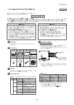
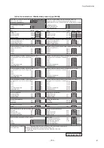
Installation procedure
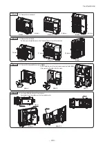
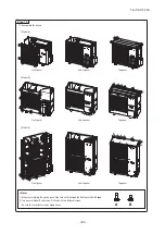
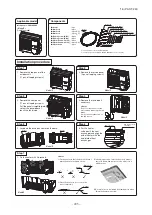
1. Remove the top panel of the
outdoor unit
(11 pcs of tapping screws).
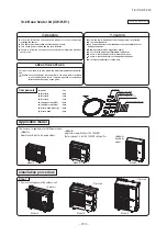
Components
Applicable model
Model name : FDC100VNP
Step 1
2. Remove the service panel
(4 pcs of tapping screws).
Step 2
3. Remove the front panel
(11 pcs of tapping screws).
Pull the panel straightforward
so that the panel doesn’t
touch the fan blade.
Step 3
4. Remove the fan blade if
necessary.
<Note>
Do not rotate the axis of fan
motor when removing the fan
blade.
It may cause malfunction of
the fan motor.
Step 4
5. Lay down the drain pan heater on the base.
Step 5
6. Put the heater
underneath the heat
exchanger and align the
end of heater with the
end plate of heat
exchanger.
Step 6
End of Heater
End plate of Heat
exchanger
Heater
Heater
●
Heater
: 1pc
●
Bracket A
: 4pcs
●
Bracket B
: 1pcs (
※
1)
●
Bracket C
: 1pcs (
※
1)
●
Tapping screw (OD5)
: 4pcs
●
Tapping screw (OD4)
: 4pcs
●
Plastic band with clip
: 2pcs
●
Plastic band with clip
: 2pcs (
※
2)
●
Plastic band
: 5pcs
Heater
Plastic band with clip
(
※
2)
Tapping screw (OD5)
Tapping screw (OD4)
Bracket A
Bracket B (
※
1)
Bracket C (
※
1)
Plastic band without clip
Bracket A
Base
Heater
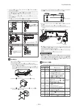
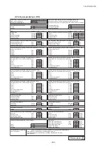
7. Fix the heater with 4 brackets.
<Note>
1) Fix the heater so that the bracket doesn’t
pinch the heater as figure shows.
2) Place the heater so as to touch the
base completely.
3) In bending position, twist the heater to make it
easier to bend, and get back to be able to fix it
with bracket.
<Note>
1) Do not fasten the heating part with the plastic
band.
There is a marking on the end of heating part.
2) When the heater is laid down
correctly, the end of heating part
comes to the corner of the base.
4) Be careful not to be injured by aluminum fin when
fixing the heater with screw.
Step 7
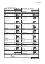
9. Lay down the wiring on the same route of fan motor wiring.
Step 9
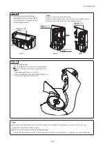
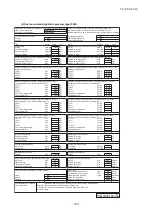
12. Reassemble the panels.
Use screw B for all places.
Use screw B for all places.
<Note>
●
This heater should have bending radius of at least 25mm including non-heating part. Do not bundle the excess part of the wire. It may cause
disconnection of the heater or insufficient capacity.
●
Be sure to prevent the heater from touching any refrigerant piping.
Especially, pay close attention not to make it touch with pipes which are close to the wiring route such as suction pipe, check valve and check joint.
Step 12
3) Top panel
<Note>
1) When reassembling the service panel, take care not to damage the front panel with the edge.
2) There are two different length of screws.
Be sure to use correct screw.
Long screw A: used for Top panel other than fixing fan bracket.
Short screw B: other place than A.
10. Insert the connector to the port CnF (White).
Step 10
Step 11
8. Insert the plastic band with clip on the designated
place (3 places), and fix the heater.
Step 8
A
B
2) Service panel
1) Front panel
Heater
Base
11. Reassemble the fan blade.
Take care to align the D-cut of motor shaft and the fan blade.
▼
mark on the center of the fan shows the position of D-cut.
<Note>
1. Tightening torque of the nut is 4.0-4.9 N·m.
2. Do not rotate the axis of fan motor when tightening the nut.
It may cause malfunction of the fan motor.
✕
✕
✓
✕
✓
Connector CnF
(White)
Clip Heater
Fan motor wiring
A A B
B
A
A
A
A
A
A
A
Plastic band with clip
Plastic band with clip
Heater
✕
✓
Marking
Marking
Plastic band with clip
Model D
Model D
Model D
Model D
Model D
Model D
Model D
Model D
Model D
Model D
A
A
A
A
<Model D>
Single fan model
※
1 This part is not used for FDC 100VNP
※
2 These parts are equipped with FDC 100VNP as accessory part
PCZ012D007B


