-
69
-
'16 • PAC-T-240
④
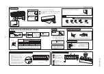
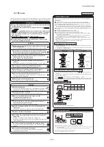
Refrigerant piping
⑤
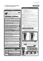
Drain pipe
④
Refrigerant piping (Continued)
⑥
Wire extracting position and wire connecton (Continued)
⑦
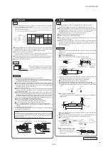
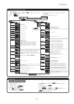
Check list after installation
●
Check the following items after all installation work completed.
Check if;
Expected trouble
Check
The indoor and outdoor units are fixed securely?
Falling, vibration, noise
Inspection for gas leakage is done?
Insufficient capacity
Insulation work is properly done?
Water leakage
Water is drained properly?
Water leakage
Power Source voltage is same as mentioned in the model name plate? PCB burnt out, not working at all
There is mis-wiring or mis-connection of piping?
PCB burnt out, not working at all
Earth wiring is connected properly?
Electric shock
Cable size comply with specified size?
PCB burnt out, not working at all
Any obstacle blocks airflow on air inlet and outlet?
Insufficient capacity
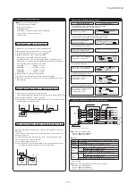
⑥
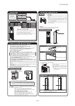
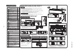
Wire extracting position and wire connecton
Open the air inlet grill by
holding the grips with
both hands and pulling to
this side.
Control box is located as
illustrated at left. Remove
the cover and make
connections.
Main fuse specification
Specification
Part No.
T3.15A L250V
SSA564A149AF
WARNING
CAUTION
Drain socket
Procedure
Backward extraction
85
94
Liquid pipe
Gas pipe
Sideward extraction
94
143
Control box
Control box
Clamp (for fixing)
Clam (For guide)
Main fuse
Grounding line
Power cable
Terminal block for signal wire
Terminal block for power cable
Clamp (For fixing)
(Unit front)
(Unit right side)
(Unit front)
(Unit right side)
For side extraction (at right and left)
(ø100 knock-out hole)
For backward extraction
(ø100 knock-out hole)
t
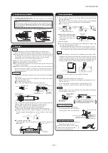
Do not insert the drain pipe directly in the drain ditch where toxic gases such as
sulffuric gas are produced.
Toxic gas may flow into the room.
t
Install the drain pipe properly according to the installation manu And insulate it to
prevent from dew condensation.
Improper installation of drain pipe may cause damage of furniture drainage water
leaked or dew condensation.
Upward bend not allowed
Trap not allowed
Submersion in water not allowed
Decline the pipe lightly.
t*OTVMBUFUIFESBJOQJQFUPQSFWFOUEFXJOH &TQFDJBMMZJOSPP
m and unit)
t
Incline the drain pipe downward to the outlet
–
Upward bend or trap is
not allowed on the way.
t6TFBDPNNFSDJBMIBSEQPMZWJOZMDIMPSJEFQJQF17GPSUIF
drain pipe.
<Use of adhesive agent is prohibited.>
ATTENTION:
. Connect the drain socket to the drain pipe
71
provided at site and fix the joint with
adhesive tape
or the like.
. When the pipe provided at site runs through a room
insulate the pipe with a commercial insula
UPS 1
olyethylene foam: Specific gra
WJUZUIJDLOFTTNNPSNPSFUPQSFWFOUEFXJOH
①
3FNPWFUIFDPOUSPMCPYDPWFS mYFEXJUIBTDSFX
②
Introduce wires in the unit and connect securely on the terminals.
③
Fix each wire with a c
MBNQ GPSmYJOH
④
Install removed parts as they were.
Procedure
t.BLFTVSFUPQBTTUIFQPXFSDBCMFUISPVHIUIFDMBNQ GPSHVJE
e).
●
Electric work must be made by qualified electricians according to the “Engineering
standards concerning electric equipment”, “Extension wiring regulations” and the
electric wiring work manual. Be sure to use dedicated electric circuits.
●
Make sure to use specified wires for wiring, and connect them securely. Clamp the
wires to protect the terminal connection from external force.
●
Make sure to protect the unit with the D-type grounding work.
●
For details of wiring work, refer to the attached electric wiring work manual.
Control box position and power cable connection
◆
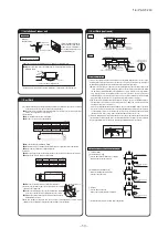
Pipe and wire extracting position
400
48
93
600
468
Liquid pipe
Gas pipe
Downward extraction
440
Liquid pipe
Gas pipe
61
14
3
30
5
Pipe cover
(For liquid pipe)
(Unit front)
(Unit bottom)
(Unit right side)
Pipe cover
(For gas pipe)
For downward
extraction
(ø100 hole)
ATTENTION:
t%POPUDVUPGGUIFnBOHFBUUIFIPMFPOUIF
base plate for the downward extraction.
Pipe cover
(Liquid pipe)
Pipe cover
(Gas pipe)
Liquid pipe
Gas pipe
Pipe cover
(For liquid pipe)
Pipe cover
(For gas pipe)
PGA012D404A
A
●
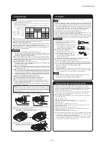
Be sure to use new pipes for the refrigerant pipes. Use the flare nut attached to the product
or a nut compa
UJ*4#$MBTT
Regarding whether existing pipes can be reused or not, and the washing method, refer to the instruction manual of the
outdoor unit, catalogue or technical data.
1) In case of reuse: Do not use old flare nut, but use the one attached to the unit or compatible with JIS B 8607, Class 2.
2) In case of reuse: Flare the end of pipe replaced partially for R410A.
●
Use phosphorus deoxidized copper allo
ZTFBNMFTTQJQF $5TQF*4)GPSSFGSJHFS
ation pipe installation.
In addition
make sure there is no damage both inside and outside of the pipe
and no harmful
substances such as sulfur
oxide
dust or a contaminant stuck on the pipes.
●
Do not use an
ZSFGSJHFSBOUPUIFSUIBO3"
Using other refrigerant except
3" 3
etc.) may degrade inside refrigeration oil. And air getting into
refrigeration circuit may cause over
QSFTTVSFBOESFTVMUBOUJUNBZSFTVMUJOCVSTUJOH
etc.
●
Store the copper pipes indoors and seal the both end of them until they are brazed in order to avoid any dust
dirt or
water getting into pipe. Otherwise it will cause degradation of refrigeration oil and compressor breakdown
etc.
●
6TFTQFDJBMUPPMTGPS3"SFGSJHFSBOU
.
Caution
D
Protruding
dimension
Flare die
d
mm
6.35
9.52
12.7
15.88
19.05
For R410A Conventional tool
Pipe dia.
Min. pipe
wall thickness
Protruding dimension for flare, mm
Rigid (Clutch type)
Flare O.D.
Flare nut
tightening torque
0
ー
0.5
0.7
ー
1.3
D
mm
8.9
ー
9.1
12.8
ー
13.2
16.2
ー
16.6
19.3
ー
19.7
23.6
ー
24.0
N·m
14
ー
18
34
ー
42
49
ー
61
68
ー
82
100
ー
120
mm
0.8
0.8
0.8
1
1.2
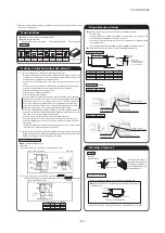
. Remove the flare nut and blind flanges on the pipe of the indoor unit.
※
.
ake sure to loosen the flare nut with holding the nut on pipe side with a spanner and giving torque to the
nut with another spanner in order to avoid unexpected stress to the copper pipe
and then remove them.
(BTNBZDPNFPVU
at this time
but it is not abnormal.)
●
1
ay attention whether the flare nut pops out.
BTUIFJOEPPSVOJUJTTPNFUJNFTQSFTTVSFE
.
.BLFBnBSFPOMJRVJEQJQFBOEHBTQJQF
and connect the refrigeration pipes on the indoor unit.
※
Bend radius of pipe must be 4D or larger. Once a pipe is bent
do not readjust the bending.
Do not twist a pipe or colla
QTFUP%PSTNBMMF
r.
※
Do a flare connection as follows:
●
.BLF
sure to loosen the flare nut with holding the nut on pipe side with a spanner and giving
torque to the nut with another spanner in order to avoid unexpected stress to the copper
pipe
and then remove them.
●
When fastening the flare nut
align the refrigeration pipe with the center of flare nut
screw
the nut for
times by hand and then tighten it by spanner with the specified torque
mentioned in the table above.
.BLF
sure to hold the pipe on the indoor unit securely by a
spanner when tightening the nut in order to avoid unexpected stress on the copper pipe.
. Cover the flare connection part of the indoor unit with attached insulation material after a gas
leakage inspection
and tighten both ends with attached straps.
●
.BLFTVSFUPJOTVM
ate both gas pipes and liquid pipes completely.
※
Incomplete insulation may cause dew condensation or water dropping.
●
Use hea
USFTJTUBOU
°C or more) insulations on the gas side pipes.
●
In case of using at high humidity condition
reinforce insulation of refrigerant pipes.
Surface of insulation may cause dew condition or water dropping
if insulations are not reinfoced.
4. Refrigerant is charged in the outdoor unit.
As for the additional refrigerant charge for the indoor unit and piping
refer to the installation
manual attached to the outdoor unit.
<
The case of using thicness of insula
UJPOJTNN
>
<
The case of using reinfoced insulation
>
1JQFDPWFS
"DDFTTP
ry)
Band
"DDFTTP
ry)
Band
1SFQBSFPOTJUF
Insulation
1SFQBSFPOTJUF
1JQFDPWFS
1SFQBSFPOTJUF
Band
"DDFTTP
ry)
The thckness of
insula
UJPOJTNN
Work procedure
Refrigerating machine oil should not be applied to the threads of union or external surface of flare. It
is because
even if the same tightening torque is applied
the oil is likely to decrease the slide friction
force on the threads and increase
in turn
the axial component force so that it could crack the flare
by the stress corrosion.
Refrigerating machine oil may be applied to the internal surface of flare only.
Caution:
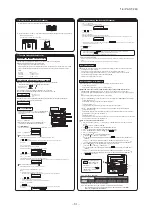
③
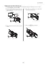
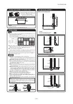
Carrying-in and installation of the unit (Continued)
①
3FNPWFUIF-mUUJOHTNPVOUFEPOUIFVOJUXJUITDSFXT
②
Turn over the
-mUUJOH
and fix it to the unit and
either the floor or the wall as illustrated.
・
F
JYJOHQPTJUJPOPGUIF-mUUJOHTBSFBTJMMVTUS
ated below.
ATTENTION:
t*OTUBMMUIFVOJUPOUIFMFWFM
*ODMJOBUJPONVTUCFMFTTUIBO¡JOGPSFBGUBOESJHIUMFGUE
irections.
F
JYJOHUIFVOJUXJUIUIF-mUUJOHT
Fixing position (L fitting)
622.5
17.5
35
15
2×φ8

