'19 • PAC-DB-333
201802
PJZ012D122
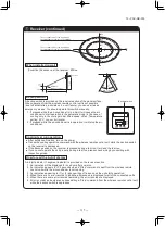
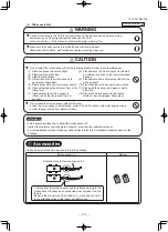
(1) Places exposed to direct sunlight
●
Do not install the motion sensor kit at the following places in order to avoid malfunction.
(2) Places near heat devices
(3) High humidity places
(4) Hot surface or cold surface enough to
generate condensation
(5) Places exposed to oil mist or steam directly
(6) Places affected by the direct air flow of
the Indoor unit
(7) Places where the motion sensor is
influenced by the fluorescent lamp or
sunlight
(8) Places where the motion sensor is affected
by infrared rays of any other communication
devices
(9) Places where some object may obstruct the
motion sensor
(10) Place that the motion sensor have a shock
(11) Place with the strong radio wave or Static
electricity
(12) Place that motion sensor lens become
tainted or have damaged. Dusty place
(13) Place where it runs in parallel with strong
voltage lines such as power source wiring
●
Do not leave the motion sensor without the cover.
In case the cover needs to be detached, protect the motion sensor with a packaging or bag.
In order to keep it away from water and dust.
• This manual describes how to install the motion sensor kit.
• Instruct the customer how to operate it correctly referring to the instruction manual.
• For the installation method of the air-conditioner itself, refer to the installation manual enclosed in the
package.
●
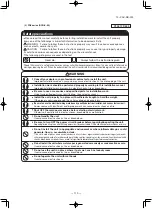
Connect the wiring to the PCB in the control box on the indoor unit and hold the wiring
securely so as not to apply unexpected stress on the PCB.
Loose connection or hold will cause abnormal heat generation or fire.
●
Make sure the power source is turned off when electric wiring work.
Otherwise, electric shock, malfunction and improper running may occur.
WARNING
CAUTION
Attention
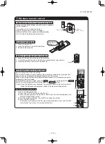
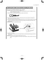
Accessories
Installing the motion sensor
Please make sure that all components are in the package.
ø
Please prepare a relay wiring for connecting the motion sensor and indoor unit on site. (0.2 mm
2
or
thicker, triplex (red, white and black) cable for communication, with the maximum length of 8 m.)
Motion sensor
Wiring <1>
Wiring <2>
2 screws
Manual
In case of CnL connector
on the indoor unit PCB
(FDT/FDK/FDTC)
In case of CnL connector
is not on the indoor unit
PCB
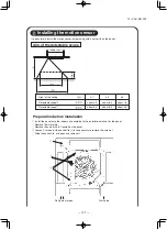
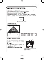
• The recommended height is lower than 4000mm for motion sensor. When the installation height is higher,
motion detection accuracy might be reduced.
• Sensor will detect the object with a different temperature from the surrounding.
• Motion sensor is more sensitive to motions in the direction of
mark.
• Sensor may not detect small children or infants with little motion.
• Although motion sensor can be installed on a wall, it is recommended to install it on the ceiling plane.
• If the sensor is installed on the wall, the sensing distance in the front direction is about 5m, covering the
angle of about 100 degrees.
Height of the ceiling h (m)
2.7
3.5
4.0
Detectable area
φ
A (m)
4.5
6.4
7.6
Detectable area
φ
B (m)
6.4
8.3
9.5
The detectable area
0.
8
h
φ
A
φ
B
Ceiling plane
Floor face
Side of screws for fixing the case
Installing the motion sensor
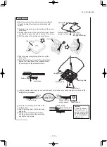
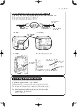
There are the following 3 methods to install the motion sensor
on the ceiling plane or wall surface (hereinafter called “ceiling
plane”). Select the method according to the installation
position.
<How to install>
(A) Direct installation by screws to the ceiling plane with
the wiring in the ceiling space.
(B) Direct installation by screws to the ceiling plane with
the wiring in the room.
(C) Installation with switch box (prepare at the site)
20.5
4.5
φ
15
5.
22
5.
2
Positional relation for pulling out relay wiring
hole and installing holes.
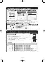
Option (A)
▶
strength to install the motion sensor directly with
screws.
①
Prepare a relay wiring on site and lay out the wiring
in advance.
②
Remove the screw at the side of the motion sensor
and slide the upper case in the direction of the arrow.
③
Pull the wiring of the motion sensor as below.
④
Pass the relay wiring through the hole on the
lower case.
⑤
tighten it in 2 locations of the installing holes
(4 locations) with the attached screws.
Upper case
Screw
Lower case
Ceiling plane
Relay wiring
(prepare on site)
φ
15 hole
(for passing
through the wiring)
Relay wiring
Lower case
Ceiling plane
Installing hole
Screws
Installing hole
⑥
Using a crimping terminal, etc., connect the same color to the relay wiring (prepare on site) and the
wiring of motion sensor.
Relay wiring
Wiring from the
motion sensor
Connect
wirings with the
same colors
White
Red
Black
White
Sensor board
Red
Black
⑦
Place the connecting part inside of the
ceiling space.
⑧
Seal the wiring hole on the lower case
with putty.
⑨
Taking care not to pinch the wirings,
slip the upper case into the lower case,
and tighten the screws.
Option (B)
▶
screws.
①
Remove the screw at the side of the motion sensor and slide the upper case in the direction of the arrow.
(The same as
②
of Option (A))
②
Pull the wiring of the motion sensor toward the side. Cut off the thinner part of the upper case.
③
in 2 locations of the installing holes (4 locations) with the
attached screws. (The same as
⑤
of Option (A))
④
Using a crimping terminal, etc., connect the same color to
the relay wiring (prepare on site) and the wiring of motion
sensor.
(The same as
⑥
of Option (A))
⑤
Taking care not to pinch the wirings, slip the upper case
into the lower case, and tighten the screws.
(The same as
⑨
of Option (A))
⑥
Seal the cut part at Step
②
with putty.
Option (C)
①
Set up the switch box and
relay wiring (prepare on site) in
advance.
Seal the relay wiring inlet with
putty.
Lower case
Upper case
Thinner part
Connecting part
Relay wiring
Caution
:
In order to prevent
tracking, be sure to
perform construction
so as not to clog up
the connecting part
with dust, etc.
φ
15 hole (ceiling hole)
for passing through the wiring
φ
15 hole
(ceiling hole)
for passing
through the wiring
Switch box
Switch box
Conduit pipe
(prepare on site)
Seal with putty
Wall
Lock nut
(prepare on site)
Switch box
(prepare
on site)
Bushing
(prepare on site)
Switch box
(prepare on site)
Relay wiring
(prepare on site)
Positional relation for the switch box and installing holes
- 129 -

