'19 • PAC-DB-333
Indoor Unit
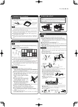
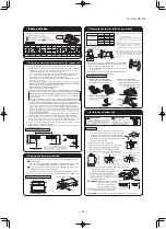
Ceiling surface
Level gauge
(Accessary of the indoor unit)
(inserted into the unit)
Ceiling opening
dimensions
10
+
4
0
Keep the distance between 10-14mm.
Exceeding the range of the distance
may cause failure etc.
①
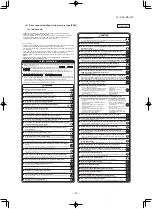
Before installation
③
Removing the inlet grille
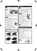
Accessories
Follow installation manual carefully, and install the panel properly.
Check the following items.
Accessories
Note: Accessories are laid in the position removing the corner lid.
1.
2.
④
Removing the corner lid
Caution
Function
WARNING
Bolt
Strap
Screw
4 pieces
4 pieces
4 pieces
For panel installation
For avoiding the corner panel from falling
For fixing the corner panel
②
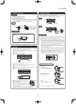
Checking the indoor unit installation position
for details.)
⑥
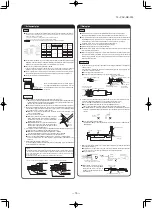
Installing the panel
Pull the corner lid toward the direction indicated by the arrow and remove it. (Same way for all 4 corner lids)
Read this manual together with the indoor unit’s installation manual.
Fasten the wiring to the terminal securely and hold the cable securely so as not to apply
unexpected stress on the terminal.
Loose connection or hold will cause abnormal heat generation or fire.
Make sure the power source is turned off when electric wiring work.
Otherwise, electric shock, malfunction and improper running may occur.
Read this manual together with the air-conditioner installation manual carefully.
Check if the opening size for the indoor unit is correct with the level gauge supplied in the indoor unit.
Check if the gap between the plane and the indoor unit is correct by inserting the level gauge into the air outlet
port of the indoor unit. (See below drawing)
Adjust the installation elevation if necessary.
Remove the level gauge before installing the panel.
If there is a height difference beyond the design limit
between the installation level of the indoor unit and the
panel, the panel may be subject to excessive stress
during installation and it may cause distortion and
damage.
•
•
The Anti draft panel has the anti draft mechanism. If the Anti draft panel is installed and the anti draft function is
set, the anti draft function will be oprerated and reduce the draft feeling. (Refer to for details.)
•
•
•
•
•
•
•
•
•
The installation level of the indoor unit can be adjusted finely
from the opening provided on the corner, even after panel is Installed.
(Refer to
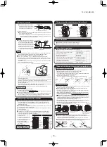
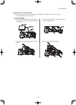
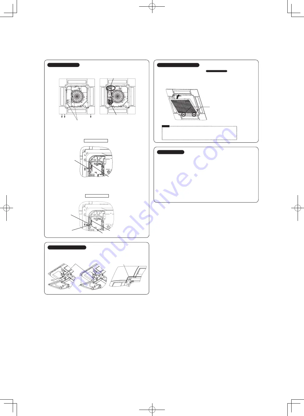
Hold the stoppers on the inlet grille (2 places) toward
OPEN direction, open the inlet grille.
Remove the hooks of the inlet grille from the panel while it
is in the open position.
⑦
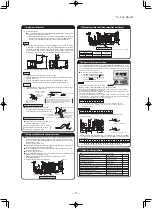
Electrical wiring
⑧
Installing a corner lid
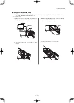
1. To avoid unexpected falling of the corner lid, put the strap onto the corner lid's pin with turning the strap up.
2. Then hang the strap of a corner lid onto the panel’s pin.
3. First insert the part “a” of a corner lid into the part “A” of the panel, and then engage 2 hooks.
4. Fix with screw.
⑨
To attach the inlet grille, follow the procedure described in in the reverse order.
1.
2.
③
Removing the inlet grille
<Installation>
Caution
•
•
•
Installing the
inlet
grille from the hinge side.
Be careful in the
inlet
grille Installing, unstable installing may cause grille falling.
Repair or replace the distorted, broken stopper at once, or the grille falling may occur.
Hang the hooks of the inlet grille in the hole of the panel. (The hooks of the grille can be hanged in 4 side of the
panel as following.)
After the grille is hanged, close the grille while the stoppers(2 places) on the grille are kept pressed to “OPEN”
direction. When the grille comes to the original position, release the stoppers to hold the grille. Make sure to hear
the sound of “CLICK” in both stoppers.
<For the Anti draft panel>
1. Loosen 2 screws on the control box lid of the indoor unit, and remove the lid by sliding it.
2. Pass the flap motor cable (20-wire) through the hook of the control box, and connect to CnJ1 (20P, white).
3. Pass the anti draft motor cable (20-wire) through the hook of the control box, and connect to CnJ2 (20P, white).
4. Fix the control box lid of the indoor unit, and tighten the 2 screws.
Flap motor connector (CnJ1, 20P, white)
Hook of the control box
Hook of the control box
Pass-through hole of the control box
Flap motor connector (CnJ1, 20P, white)
Anti draft motor connector (CnJ2, 20P, white)
Signal line connection section
Signal line connection section
The wiring work varies depending on the panel type. Select the wiring work appropriate for the panel type.
The connection positions of the indoor unit are as shown below irrespective of the panel type.
<For the Standard panel>
1. Loosen 2 screws on the control box lid of the indoor unit, and remove the lid by sliding it.
2. Pass the flap motor wiring (20-wire) through the hook of the control box, and connect to CnJ1 (20P, white).
3. Fix the control box lid of the indoor unit, and tighten 2 screws.
Accessories holding position
<Removal>
Stopper
Closing direction
Position for hanging hinges
A
a
Pin
Screw
Coner lid
Installing the inlet grille
⑩
Panel setting
<Flap swing range setting (Individual flap cotrol setting)>
It is possible to change the swing range of the flap by the wired remote control. Once the upper and lower limit
positions are set, the flap will swing within the set range.It is also possible to set the different range to each flap.
<Anti draft setting>
For the Standard panel
For the Anti draft panel
Pull up around this part as shown in the picture.
The anti draft function will not be operated if the anti draft panel is installed and its wirings are only connected.
To operate the anti draft function, enable the anti draft setting by using the wired or wireless remote control.
Note: It is not possible to set by the following remote control models or older.
Wired:RC-EX1A, RC-E5, RCH-E3
Wireless: RCN-E1R
Once you have enabled the settings in this mode, the anti draft function is operated when the air-conditioner is
started, and the parts of the anti draft mechanism are always open when the air-conditioner is operating. When the
air-conditioner is stopped, they are closed. It is possible to enabled or disabled the anti draft function for each air
outlet.
For the setting details, refer to the user’s manual supplied with the remote control.
Drain pipe
Refrigerant pipes
It is possible to open the lid of the control box by loosening
the screws of the lid and sliding it as shown below.
Power line connection section
Signal line connection section
⑥
Installing the panel
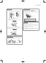
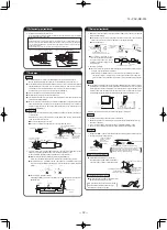
1. Temporary hanging
Lift up the hanger (2 places) on the panel for temporary support.
Hang the panel on the hook on the indoor unit.
2. Fix the panel on the indoor unit
Fasten the panel on the indoor unit with the 4 bolts supplied with the panel.
Caution
Air leakage
Air leakage along
the ceiling
Fouling
Dew condensation or dripping
Make sure no gap is left here.
Caution
It is possible to adjust the installation height of the indoor unit with the panel installed as long
as there is no influence on the drain pipe inclination and/or the indoor unit levelness.
Do not give any stress on the panel when adjusting the height of the indoor unit to
avoid unexpected distortion. It may cause the distortion of panel or failing to close the
inlet grille, and the parts of the anti draft mechanism.
•
•
•
•
•
•
•
DRAIN
PIPE SIDE
⑤
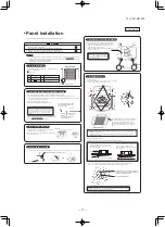
Orientation of the panel installation
Take note that there is an orientation to install the panel.
Install the panel with the orientation shown on the right.
CAUTION
Align the “PIPE SIDE” mark (on the panel) with the
refrigerant pipes on the indoor unit.
Align the “DRAIN” mark (on the panel) with the drain
pipe on the indoor unit.
In case the orientation of the panel is
not correct, it will lead to air leakage
and also it is not possible to connect
the flap motor wiring.
•
•
•
Control box
Refrigerant pipes
Drain pipe
Unit’s hook
Panel’s fixing hanger
Hook
hanger
The Anti draft panel moves the parts of the anti draft
mechanism (shaded area,4 places).Note that they
may break if they are moved forcibly by hand.
Although the parts (shaded area) of the Standard
panel are separate parts from the body, they do not
move.
Caution
The parts (shaded area), of the anti draft mechanism around the air outlet, are separate parts.
Handle the panel with care.
Especialy, the shaded area of the Anti draft panel move. Note that they may break if they are
moved forcibly by hand.
To adjust finely, please turn a nut fastening
the indoor unit using a spanner or similar tool
from the opening on the corner.
Bolt for installing the panel
If there is a gap between the ceiling and the
panel even after the fixing bolts are
tightened, adjust the installation level of the
indoor unit again.
Improperly tightened fixing bolts cause the
problems listed below, so make sure that bolts
are securely tightened.
PJF012D037
⑩
Panel setting
・
Standard panel : without the anti draft mechanism
・
Anti draft panel : with the anti draft mechanism
B
- 52 -


