'19 • PAC-DB-333
- 63 -
⑩
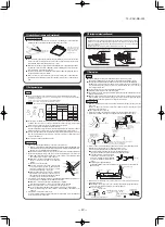
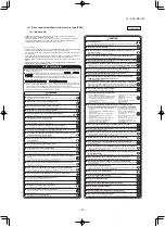
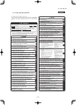
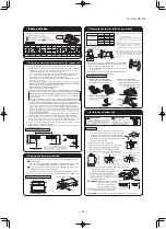
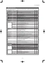
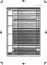
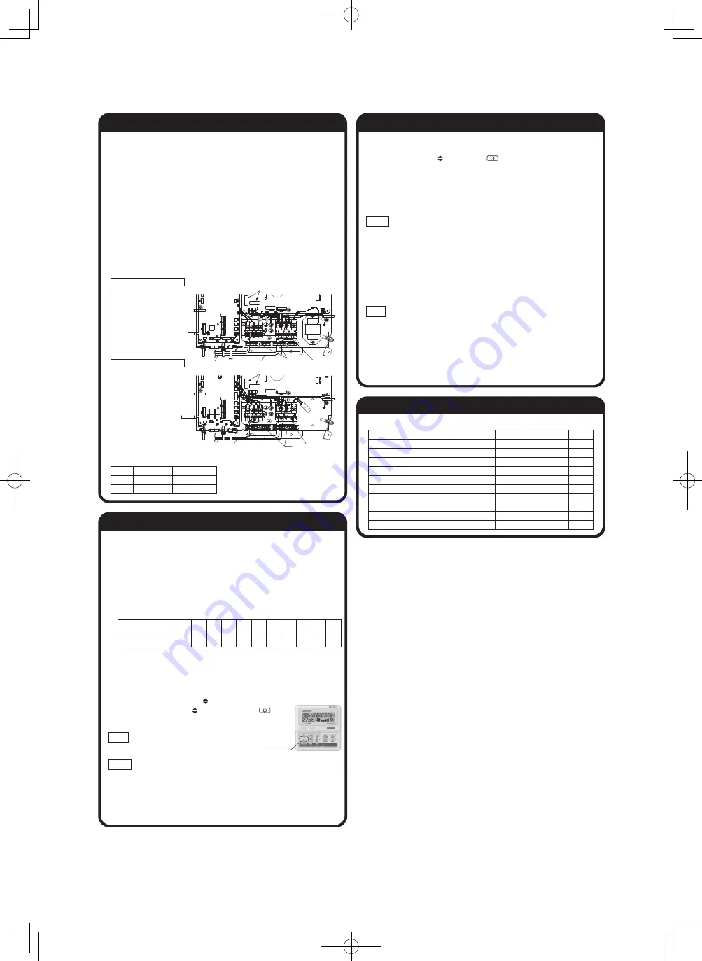
Check list after installation
●
Check the following items after all installation work completed.
Check
Check if
The indoor and outdoor units are fixed securely?
Inspection for leakage is done?
Insulation work is properly done?
Water is drained properly?
Power source voltage is same as mentioned in the model name plate?
No mis-wiring or mis-connection of piping?
Earth wiring is connected properly?
Cable size comply with specified size?
Any obstacle blocks air flow on air inlet and outlet?
Is setting of E.S.P finished?
Expected trouble
Falling, vibration, noise
Insufficient capacity
Water leakage
Water leakage
PCB burnt out, not working at all
PCB burnt out, not working at all
Electric shock
PCB burnt out, not working at all
Insufficient capacity
Excessive air flow, water drop blow out
⑨
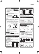
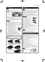
External static pressure setting (continued)
●
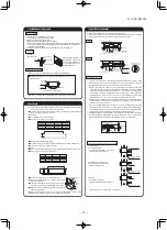
How to start automatic setting
①
,
②
Same setting as MANUAL SETTING.
③
Select [AUT] by using button and press button .
②
After setting E.S.P. at "AUT", operate unit in FAN mode with certain fan speed (Lo-Uhi).
Indoor unit fan will run automatically and recognize E.S.P. by itself.
The operation for automatic E.S.P. recognition will last about 6 minutes, and it will be stopped
after recognition is completed.
Caution
· Be sure to execute AUTOMATIC SETTING by remote control AFTER ducting work is completed.
When duct specification is changed after AUTOMATIC SETTING, be sure to execute AUTOMATIC
SETTING again after power resetting and turning on again.
· Be sure to execute AUTOMATIC SETTING before trial cooling operation.
(See ELECTRICAL WIRING WORK INSTRUCTION about trial cooling operation)
· Before AUTOMATIC SETTING, be sure to check that return air filter in duct is installed and
damper is opened.
Wrong procedure causes excessive air flow or water drop blown out.
Notice
· During operation for automatic recognition (the Auto Operation), fan rotates with certain speeds
regardless of set fan speed by remote control.
· When duct is set with low static pressure (around 10-50Pa), even if indoor unit operate with
higher air flow volume than rated one, but it is not abnormal.
· When you changed operation mode or stop operation with ON/OFF button during Auto Opera-
tion, the Auto operation will be canceled.
· In such case, be sure to execute AUTOMATIC SETTING again according to above procedure.
⑨
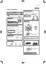
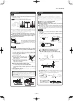
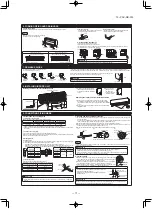
External static pressure setting
You can set External Static Pressure (E.S.P.) by either method of MANUAL SETTING or AUTO-
MATIC SETTING by remote control.
Indoor unit will control fan-speed to keep rated air flow volume at each fan speed setting (Lo-Uhi)
1. MANUAL SETTING
You can set required E.S.P. by wired remote control that calculated with the set air flow rate
and pressure loss of the duct connected.
Select No.1-10 (10Pa-100Pa) from following table according to calculation result.
Refer to technical manual for details of air flow characteristic.
※
When you set No.11-19 by remote control, unit will control fan-speed with setting of
No.10 Factory default is at No.5.
●
How to set E.S.P by wired remote control
①
Push "
◆
" marked button(E.S.P button).
②
Select indoor unit No. by using button.
③
Select setting No. by using button and set E.S.P. by button.
See detailed procedure in technical manual.
Notice
You can not set E.S.P. by wireless remote control.
Caution
Be sure to set E.S.P. according to actual duct connected.
Wrong settings causes excessive air flow volume or water drop blown out.
2. AUTOMATIC SETTING
Indoor unit will recognize E.S.P. by itself automatically and select appropriate fan speed No.1-10.
Setting No.
External Static Pressure (Pa)
1
10
2
20
3
30
4
40
5
50
6
60
7
70
8
80
9
90
10
100
E.S.P. button
⑧
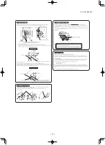
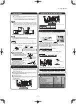
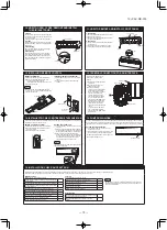
Wiring-out position and wiring connection
●
Electrical installation work must be performed according to the installation manual by an
electrical installation service provider qualified by a power provider of the country, and be
executed according to the technical standards and other regulations applicable to electrical
installation in the country.
Be sure to use an exclusive circuit.
●
Use specified cord, fasten the wiring to the terminal securely, and hold the cord securely in
order not to apply unexpected stress on the terminal.
●
Do not put both power source line and signal line on the same route. It may cause miscom-
munication and malfunction.
●
Be sure to do D type earth work.
●
For the details of electrical wiring work, see attached instruction manual for electrical wiring
work.
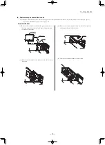
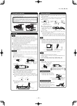
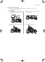
1. Remove a lid of the control box (2 screws).
2. Hold each wiring inside the unit and fasten them to terminal block securely.
3. Fix the wiring with clamps.
4. Install the removed parts back to original place.
Single unit wiring connection
Multi unit wiring connection
PJG012D021
* Please fix the wiring in the band not to move even if it pulls.
Main fuse specification
Specification
T3.15A L250V
T5A L250V
Model
22-56
71-160
Part No.
SSA564A149AF
SSA564A149AH
Earth
Earth
Power source line
Signal line
Remote control line
*
*
Indoor - Outdoor connecting line
Remote control line
Main fuse
Main fuse

