'19 • PAC-DB-333
2. REFRIGERANT PIPING WORK
1)
Restrictions
on
unit
installation
and
use
●
Check
the
following
points
in
light
of
the
indoor
unit
specifications
and
the
installation
site.
●
Obse
rve
the
following
restrictions
on
unit
installation
and
use.
Improper
installation
can
result
in
a
compressor
failure
or
pe
rformance
degradation
.
2)
Determination
of
pipe
size
●
Determine
refrigerant
pipe
size
pursuant
to
the
following
guidelines
based
on
the
indoor
unit
specifications.
Gas pipe
Liquid pipe
ø15.88
ø6.35
Flare
Flare
ø15.88
ø6.35
ø15.88
ø9.52
1. HAULAGE AND INSTALLATION
(T
ake particular care in car
rying in or moving the unit, and always pe
rform such an operation with two or more persons.)
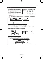
Intake
The
height
of
a
wall
is
1200mm
or
less.
(
se
rvice
space
)
Intake
Outlet
Fasten
with
bolts
(M10-12)
Use
a
thicker
block
to
anchor
deepe
r.
Use
a
long
block
to
extend
the
width.
CAUTION
When
a
unit
is
hoisted
with
slings
for
haulage,
take
into
consideration
the
offset
of
its
gravity
center
position.
If
not
properly
balanced,
the
unit
can
be
thrown
off-balance
and
fall.
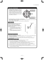
1)
Delivery
●
Deliver
the
unit
as
close
as
possible
to
the
installation
site
before
removing
it
from
the
packaging.
●
When
you
have
to
unpack
the
unit
for
a
compelling
reason
before
you
haul
it
to
the
installation
point,
hoist
the
unit
with
nylon
slings
or
ropes
and
protection
pads
so
that
you
may
not
damage
the
unit.
2)
Portage
●
The
right
hand
side
of
the
unit
as
viewed
from
the
front
(diffuser
side)
is
heavie
r.
A
person
car
rying
the
right
hand
side
must
take
heed
of
this
fact.
A
person
car
rying
the
left
hand
side
must
hold
with
his
right
hand
the
handle
provided
on
the
front
panel
of
the
unit
and
with
his
left
hand
the
corner
column
section
.
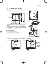
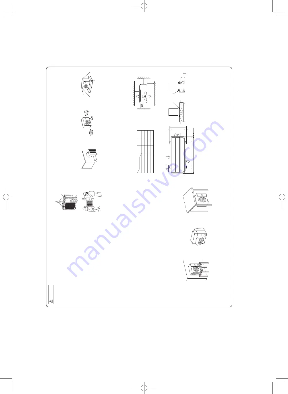
5)
Installation
space
●
W
alls surrounding the unit in the four sides are not acceptable.
●
There must be a 1-meter or larger space in the above.
●
When more than one unit are installed side by side, provide a 250mm or wider interval between them as a service space. In order to facilitate servicing of controllers, please provide a sufficient space between units so that their top plates can be removed easily.
●
Where a danger of short-ci
rcuiting exists, install guide louvers.
●
When more than one unit are installed, provide sufficient intake space consciously so that short-ci
rcuiting may not occur
.
●
Where
piling
snow
can
bu
ry
the
outdoor
unit,
provide
proper
snow
guards.
L
3
L
2
L
4
L
1
Example installation
Size
●
In installing the unit, fix the unit
’s legs with bolts specified on the above.
●
The protrusion of an anchor bolt on the front side must be kept within 15 mm.
●
Securely install the unit so that it does not fall over during earthquakes or strong winds, etc.
●
Refer to the above illustrations for information regarding concrete foundations.
●
Install the unit in a level area. (With a gradient of 5 mm or less.) Im
pr
op
er
in
st
al
la
tio
n
ca
n
re
su
lt
in
a
co
m
pr
es
so
rf
ai
lu
re
, b
ro
ke
n
pi
pi
ng
w
ith
in
th
e
un
it
an
d
ab
no
rm
al
n
oi
se
g
en
er
at
io
n.
6)
Installation
L
H
Outdoor unit
Indoor unit
CAUTION
●
Th
e
us
e
re
st
ric
tio
ns
ap
pe
ar
in
g
in
th
e
ta
bl
e
ab
ov
e
ar
e
ap
pl
ica
bl
e
to
th
e
st
an
da
rd
pi
pe
siz
e
co
m
bi
na
tio
ns
sh
ow
n
in
th
e
ta
bl
e
be
lo
w.
W
he
re
an
ex
ist
in
g
pi
pe
s
ys
te
m
is
u
til
ize
d,
di
ffe
re
nt
o
ne
-w
ay
pi
pe
le
ng
th
re
st
ric
tio
ns
sh
ou
ld
a
pp
ly
de
pe
nd
in
g
on
it
s
pi
pe
siz
e.
Fo
r m
or
e
in
fo
rm
at
io
n,
p
lea
se
se
e
“5
. U
TI
LI
ZA
TI
ON
OF
E
XI
ST
IN
G
PI
PI
NG
.”
Outdoor unit connected
Refrigerant piping (branch pipe
L)
Indoor unit connected
About brazing
When pipe is brazing.
(2)
If
the
unit
can
be
affected
by
strong
wind,
following
measures
are
required.
Strong
wind
can
cause
damage
of
fan
(fan
motor),
or
can
cause
pe
rformance
degradation,
or
can
trigger
anomalous
stop
of
the
unit
due
to
rising
of
high
pressure.
3)
Refrigerant
pipe
wall
thickness
and
material
●
Select
refrigerant
pipes
of
the
table
shown
on
the
right
wall
thickness
and
material
as
specified
for
each
pipe
size.
Pipe diameter [mm]
Minimum pipe wall thickness [mm]
Pipe material*
ø6.35
0.8
O-type pipe
ø15.88
1.0
O-type pipe
*Phosphorus deoxidized seamless copper pipe ICS 23.040.15, ICS 77.150.30
NOTE
●
Select
pipes
having
a
wall
thickness
larger
than
the
specified
minimum
pipe
thickness.
He
avy
Pad
L1
L2
L3
L4
Open
300
100
250
Open
250
150
250
500
Open
100
250
(mm)
I
II
III
60
580
340
19
380
418
19
880
87.9
15
150
150
Intake
Outlet
①
Anchor bol tfixed position
②
Notabilia for installation
Plug the end of the pipe with tape, or other material, and fill the pipe with nitrogen gas.
Only use nitrogen gas (N
2
)
Taping
<
N
2
>
Nitrogen
Brazing
Station valve
Prima
ry side
Seconda
ry side
0.5MPa
Hand
Relief valve
Nitrogen
gas
Brazing
must
be
performed
under
a
nitrogen
gas
flo
w
.
Without
nitrogen
gas,
a
large
quantity
of
foreign
matters
(oxidized
film)
are
created,
causing
a
critical
failure
from
capilla
ry
tube
or
expansion
valve
clogging.
If the refrigerant is existing in the pipe at brazing, poisonous gas is produced.
Wind
direction
Wind
direction
Over
500
mm
2.Install the outlet air blow side of
the unit in a position perpendicular to the direction of wind.
3.
The
unit
should
be
installed
on
the
stable
and
level
foundation.
If
the
foundation
is
not
level,
the
down
the
unit
with
wires.
1.
Install the outlet air blow side of the unit to face a wall of building, or provide a fence or a windbreak screen.
7) To run the unit for a cooling operation,
when the outdoor temperature is –5°C or lower.
●
When the outdoor air temperature is –5°C or lower, provide a snow hood to the outdoor unit on site. So that strong wind will not blow against the outdoor heat exchanger directly.
4)
Caution
about
selection
of
installation
location
(1)
If
the
unit
is
installed
in
the
area
where
the
snow
will
accumulate,
following
measures
are
required.
The
bottom
plate
of
unit
and
intake,
outlet
may
be
blocked
by
sno
w
.
1
2
Provide
a
snow
hood
to
the
outdoor
unit
on
site.
3
Install
the
unit
under
eaves
or
provide
the
roof
on
site.
Since
drain
water
generated
by
defrost
control
may
freeze,
following
measures
are
required.
●
Don’t execute drain piping work
by using a drain elbow and drain grommets (accessories).
[Refer to Drain piping work.]
Install the unit on the base so that the bottom is higher than snow cover surface, and draining water is secured.
●
Attached heater on a base plate on site, if there is possibility to freeze drain water. In case that the product has a corrective drainage system, the drainage paths should have suitable threatment against freezing but be sure not to melt the material of drainage paths with heat.
30m
or less
20m
or less
20m
or less
L
H
H
Restrictions
Dimensional restrictions
Marks appearing in the drawing on the right
Main pipe length
Elevation difference between
Indoor unit
indoor and outdoor units
When the outdoor unit is positioned higher
FDT, FDE, FDU, FDUM, SRK
When the outdoor unit is positioned lower
3)
S
el
ec
tio
n
of
in
stalla
tio
n
lo
ca
tio
n
fo
r
th
e
ou
td
oo
r
un
it
Be
s
ur
e
to
sele
ct
a
s
ui
ta
ble
in
st
alla
tio
n
pla
ce
in
c
on
si
de
ra
tio
n
of
fo
llo
w
in
g
co
nd
iti
on
s.
〇
A
pla
ce
w
he
re
it
is
h
or
iz
on
ta
l,
st
ab
le
a
nd
c
an
e
nd
ur
e
th
e
un
it
w
ei
gh
t a
nd
wi
ll
no
t a
llo
w
v
ib
ra
tio
n
tr
an
sm
itt
an
ce
of
th
e
un
it.
〇
A
pla
ce
w
he
re
it
c
an
b
e
fr
ee
fr
om
p
os
si
bi
lit
y
of
b
ot
he
rin
g
ne
ig
hb
or
s
du
e
to
n
oi
se
o
r
ex
ha
us
t a
ir
fr
om
th
e
un
it.
〇
A
pla
ce
w
he
re
th
e
un
it
is
n
ot
e
xp
os
ed
to
o
il
sp
la
sh
es
.
〇
A
pla
ce
w
he
re
it
c
an
b
e
fr
ee
fr
om
d
an
ge
r
of
fl
am
m
ab
le
g
as
lea
ka
ge
.
〇
A
pla
ce
w
he
re
d
ra
in
w
at
er
c
an
b
e
di
sp
os
ed
w
ith
ou
t a
ny
tr
ou
bl
e.
〇
A
pla
ce
w
he
re
th
e
un
it
wil
l n
ot
b
e
af
fe
ct
ed
b
y
he
at
r
ad
ia
tio
n
fr
om
o
th
er
h
ea
t s
ou
rc
e.
〇
A
pla
ce
w
he
re
s
no
w
wil
l n
ot
a
cc
um
ul
at
e.
〇
A
pla
ce
w
he
re
th
e
un
it
ca
n
be
k
ep
t aw
ay
5
m
o
r
m
or
e
fr
om
T
V
se
t a
nd
/o
r
ra
di
o
recei
ve
r
in
o
rd
er
to
a
vo
id
a
ny
ra
di
o
or
T
V
in
te
rf
er
en
ce
.
〇
A
pla
ce
w
he
re
g
oo
d
ai
r
ci
rc
ula
tio
n
ca
n
be
s
ec
ur
ed
, a
nd
e
no
ug
h
se
rvi
ce
s
pa
ce
c
an
b
e
se
cu
re
d
fo
r
ma
in
te
na
nc
e
an
d
se
rvic
e
of
th
e
un
it
sa
fe
ly
.
〇
A
pla
ce
w
he
re
th
e
un
it
wi
ll
no
t b
e
af
fec
te
d
by
el
ec
tr
om
ag
ne
tic
wav
es
a
nd
/o
r h
ig
h-
ha
rm
on
ic
wav
es
g
en
er
at
ed
b
y
ot
he
r
eq
ui
pm
en
t.
〇
A
pla
ce
w
he
re
c
hemic
al
s
ub
st
an
ce
s
lik
e
su
lfu
ric
g
as
, c
hl
or
ic
g
as
, a
ci
d
an
d
alka
li
(in
cl
ud
in
ga
m
m
on
ia
),
w
hi
ch
c
an
ha
rm
th
e
un
it,
wil
l n
ot
b
e
ge
ne
ra
te
d
an
d
no
t r
em
ai
n.
〇
If
a
op
er
at
io
n
is
c
on
du
ct
ed
w
he
n
th
e
ou
td
oo
r
ai
r
te
m
pera
tu
re
is
-
5˚
C
lo
w
er
, t
he
o
ut
do
or
u
ni
t s
ho
ul
d
be
in
stall
ed
at
a
p
lace
w
he
re i
t i
s
no
t i
nfl
ue
nc
ed
b
y
na
tu
ral w
in
d.
〇
A
pla
ce
w
he
re
s
tr
on
g
w
in
d wi
ll
no
t b
lo
w
a
ga
in
st
th
e
ou
tle
t a
ir
bl
ow
o
f t
he
u
ni
t.
D
o
no
t
in
st
al
l t
he
u
ni
t i
n
plac
es
w
hi
ch
e
xp
os
ed
t
o
se
a
br
ee
ze
(
e.
g.
c
oa
st
al
a
re
a)
o
r
cal
ci
um
c
hl
or
id
e
(e
.g
. s
no
w
mel
tin
g
ag
en
t)
, e
xp
os
ed
to
a
m
m
on
ia
s
ub
st
an
ce
(
e.
g.
o
rg
an
ic
fe
rt
ili
ze
r)
.
PSC012D137
Notabilia as a unit designed for R32
•
Read the “SAFETY PRECAUTIONS” ca
refully first of all and strictly follow it during the installation work in o
rder
to p
rotect yourself.
•
The p
recautionary items mentioned below a
re distinguished into two levels, and .
:
W
rong installation would cause serious consequences such as injuries or death.
:
W
rong installation might cause serious consequences depending on ci
rcumstances.
Both mentions the important items to p
rotect your health and safety so strictly follow them by any means.
•
Be su
re to confirm no anomaly on the equipment by commissioning after completed installation and explain the
operating methods as well as the maintenance methods of this eq
uipment to the user accor
ding to the owner
’s
manual.
•
Keep the installation manual together with owner
’s manual at a place whe
re any user can
read at any time.
Mo
reover if necessar
y, ask to hand them to a new use
r.
•
For installing qualified personnel, take p
recautions in
respect to themselves by using suitable p
rotective
clothing, g
roves, etc., and then perform the installation works.
•
Please pay attention not to fall down the tools, etc. when installing the unit at the high position.
•
If unusual noise can be hea
rd during operation, consult the deale
r.
•
The meanings of “Marks” used he
re a
re shown as follows:
•
This installation manual deals with outdoor units and general installation specifications onl
y. For indoor units,
refer to the
respective installation manuals supplied with the units.
•
When install the unit, be su
re to check whether the selection of installation place, power source specifications, usage limitation (piping length, height di
ffe
rences between indoor and outdoor units, power
source voltage and etc.) and installation spaces.
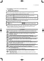
SAFETY PRECAUTION
S
Never do it under any ci
rcumstances.
Always do it acco
rding to the instruction.
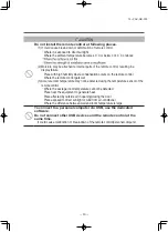
CAUTION
W
ARNING
CAUTION
W
ARNING
W
ARNIN
G
CAUTION
•
Car
ry out the electrical work for ground lead with care.
Do not connect the ground lead to the gas line
, water line
, lightning conductor or telephone line
’s ground lead
. Incorrect grounding can cause unit faults such as electric shocks due to short-circuiting.
•
Ensure that no air enters in the refrigerant circuit when the unit is installed and rem
oved.
If
ai
r e
nt
ers in
th
e
re
fri
ge
ra
nt
c
irc
ui
t, t
he
p
re
ss
ur
e in t
he
re
fri
ge
ra
nt c
ircu
it
be
co
m
es
to
o hi
gh
, w
hi
ch
c
an
c
au
se
b
ur
st
a
nd
p
er
so
na
l in
ju
ry
.
•
Do
n
ot
p
ro
ce
ss
in
g,
s
pl
ic
e
th
e
po
w
er
c
or
d,
o
r s
ha
re
a
s
oc
ke
t wit
h
ot
he
r p
ow
er
p
lu
gs
.
This may cause fire or electric shock due to defecting contact
, defecting insulation
and ove
r-current etc.
•
Use the circuit breaker for all pole correct capacit
y.
Circuit breaker
should be the one that disconnect all poles under
over current.
Using the incorrect circuit breake
r, it can cause the unit malfunction and fire.
•
Install isolator or disconnect switch on the power source wiring in accordance with the local codes and regulations.
The isolator should be locked in OFF state in accordance with EN60204-1.
•
Af
te
r m
ai
nt
en
an
ce
, al
l w
iri
ng
, w
iri
ng
ti
es
an
d
th
e li
ke
, s
ho
ul
d
be r
et
ur
ne
d
to
th
ei
r o
rig
in
al sta
te
a
nd
wi
rin
g
ro
ut
e,
a
nd
th
e
ne
ce
ss
ar
y
cl
ea
ra
nc
e
fr
om
all
m
eta
l p
ar
ts
s
ho
ul
d
be
s
ec
ur
ed
.
•
Se
cu
re
a
sp
ac
e f
or
in
stallat
io
n,
in
sp
ec
tio
n
an
d
m
ain
te
na
nc
e
sp
ec
ifi
ed
in
th
e
m
an
ua
l.
Insufficient space can result in accident such as personal inju
ry due to falling
from the installation place.
•
Earth
lea
ka
ge
b
re
ak
er
m
ust
b
e instal
le
d
If
th
e
ea
rth
le
ak
ag
e
br
ea
ke
r is
no
t in
st
al
le
d,
it
c
an
c
au
se
fir
e
or
e
le
ct
ric
sh
oc
ks
.
•
Do
no
t i
nstall
th
e
un
it i
n
th
e
lo
cati
on
s lis
ted
be
lo
w
.
•
Lo
ca
tio
ns
w
he
re
ca
rb
on
fi
be
r,
m
et
al p
ow
de
r or
a
ny
p
ow
de
r is
flo
ati
ng
.
•
Lo
ca
tio
ns
w
he
re
a
ny
subs
ta
nc
es
th
at
c
an
af
fe
ct
th
e un
it such
a
s sulphid
e
gas
,
ch
lo
rid
e g
as
, aci
d
an
d
al
ka
lin
e
ca
n
oc
cu
r.
•
Veh
ic
le
s
and shi
ps
.
•
Lo
ca
tio
ns
w
he
re
co
sm
et
ic o
r spe
ci
al sp
ra
ys
a
re
ofte
n u
sed
.
•
Lo
ca
tions
w
ith di
re
ct
ex
posu
re
o
f o
il mi
st
a
nd
st
ea
m su
ch
a
s k
itch
en a
nd
m
ach
in
e pl
an
t.
•
Lo
ca
tions
w
he
re
a
ny
m
achines
w
hich ge
ne
ra
te
high
fr
eq
ue
ncy
h
ar
m
on
ic
s a
re
us
ed
.
•
Lo
ca
tio
ns
w
ith sa
lty a
tmosphe
re
s such
as
coa
st
lin
es
.
•
Lo
ca
tio
ns
w
ith
he
av
y sn
ow
(I
f in
st
all
ed
, b
e s
ure
to
p
ro
vide
ba
se
fr
am
e
and sn
ow
ho
od
m
en
tio
ne
d i
n
th
e
m
an
ua
l).
•
Lo
ca
tions
w
he
re
th
e uni
t is
e
xp
os
ed
to
chimn
ey
smo
ke
.
•
Lo
ca
tio
ns
at
high a
lti
tud
e (m
or
e
than
1
000
m hig
h)
.
•
Lo
ca
tio
ns
w
ith
a
m
m
onic
a
tm
osp
he
res
. (e
.g
. o
rg
anic
fe
rtiliz
er
)
•
Lo
ca
tio
ns
w
ith
c
alcium chl
or
id
e (e
.g
. s
no
w
m
el
ting
a
ge
nt)
.
•
Lo
ca
tio
ns
w
he
re h
eat
ra
di
at
io
n
fro
m
o
ther h
eat
s
ou
rce
c
an
affe
ct
th
e un
it.
•
Lo
ca
tions
w
ith
ou
t g
oo
d
ai
r circu
la
tio
n.
•
Lo
ca
tio
ns
w
ith
a
ny
ob
st
acl
es
w
hich
ca
n pr
ev
en
t in
let
a
nd
o
ut
let
a
ir
of
th
e un
it.
•
Lo
ca
tio
ns
w
he
re s
ho
rt
circuit
of
a
ir
ca
n
occ
ur
(in
c
as
e
of
mu
ltip
le
uni
ts
in
st
al
la
tio
n)
.
•
Lo
ca
tio
ns
w
he
re
st
ro
ng air b
low
s
ag
ains
t t
he
ai
r o
ut
let
of
o
ut
door
un
it.
•
Lo
ca
tions
w
he
re
s
om
et
hing
lo
ca
te
d
ab
ov
e
the un
it
co
uld
fal
l.
It
ca
n
ca
us
e
re
m
ar
kab
le
d
ec
re
ase in
p
er
fo
rm
an
ce
, c
or
ro
si
on
a
nd
d
am
ag
e
of
co
mpo
ne
nts
, ma
lfu
nc
tio
n
an
d
fir
e.
•
Installation must be carried out by the qualified installe
r.
If
you i
ns
tal
l t
he
s
ys
te
m
by
y
ou
rse
lf,
it
m
ay
c
au
se
s
er
io
us
tr
ou
bl
e su
ch
a
s
w
at
er
le
ak
s,
el
ec
tri
c
sh
oc
ks
, fi
re
a
nd p
er
so
na
l in
ju
ry
, a
s
a
res
ul
t o
f a
s
ys
tem
m
al
fu
nc
tio
n.
D
o
no
t
ca
rry
o
ut
th
e ins
tall
at
io
n
and
m
ai
nt
ena
nc
e w
or
k
ex
ce
pt
b
y
the qualifi
ed in
st
al
le
r.
•
Install the system in full accordance with the installation manual.
In
co
rre
ct ins
ta
lla
tio
n
m
ay
c
au
se
b
ur
st
s,
p
er
so
na
l in
ju
ry
, w
at
er
le
ak
s,
e
le
ctr
ic
sh
oc
ks
a
nd
fi
re
.
•
Be sure to use only for household and residence.
If
thi
s
appl
ia
nc
e is ins
ta
lle
d in
in
fe
rio
r e
nv
iro
nm
en
t s
uc
h
as
m
ac
hi
ne
s
ho
p
an
d
et
c.
,
it
ca
n
ca
use
m
al
fu
nc
tio
n.
•
When installing in small rooms
, take prevention measures not to
exceed the density limit of refrigerant in the event of leakage
, referred
by the formula (accordance with ISO5149)
.
If the density of refrigerant exceeds the limit
, please consult the dealer and install the
ventilation system
, otherwise lack of oxygen can occu
r, which can cause serious accident.
•
Use the original accessories and the specified components for installation.
If parts other than those prescribed by us are used
, It may cause water leaks
,
electric shocks
, fire and personal inju
ry
.
•
Install the unit in a location with good support.
Unsuitable installation locations can cause the unit to fall and cause material
damage and personal inju
ry
.
•
Ensure the unit is stable when installed
, so that it can withstand
earthquakes and strong winds.
Unsuitable installation locations can cause the unit to fall and cause material
damage and personal inju
ry
.
•
Ve
ntila
te
th
e
w
or
ki
ng
a
re
a
w
ell in
th
e
ev
ent
o
f r
ef
rig
er
an
t l
ea
ka
ge
du
rin
g
in
stalla
tio
n.
If the refrigerant comes into contact with naked flames
, poisonous gas is produced.
•
Use the prescribed pipes
, fl
are nuts and tools for R32.
Using existing parts (for R22 or R407C) can cause the unit failure and serious
accidents due to burst of the refrigerant circuit.
•
Tighten the
flare nut by to
rque wrench with specified method.
If the flare nut were tightened with excess torque
, this may cause burst and
refrigerant leakage after a long period.
•
Do not open the se
rvice
valves for liquid line and gas line until completed
refrigerant piping work
, air tightness test and e
vacuation.
If the compressor is operated in state of opening se
rvice valves before completed
connection of refrigerant piping work
, you may incur frost bite or inju
ry from an
abrupt refrigerant outflow and air can be sucked into refrigeran
t circuit
, which can
cause burst or personal inju
ry due to anomalously high pressure in the refrigerant.
•
Th
e
el
ec
tr
ic
al
in
stalla
tio
n
m
us
t b
e
ca
rr
ie
d
ou
t b
y
th
e
qu
al
ifi
ed
e
le
ct
ric
ia
n
in
a
cc
or
da
nc
e wi
th
“
th
e
no
rm
fo
r e
le
ct
ric
al
w
or
k”
a
nd
“
nat
io
na
l w
iri
ng
re
gu
lat
io
n”
, a
nd
th
e sy
st
em
m
ust
b
e
co
nn
ec
te
d
to
th
e
de
di
ca
te
d
ci
rcu
it.
Power source with insufficient capacity and incorrect function done by improper work can cause electric shocks and fire.
•
Be sure to shut off the power before starting electrical work.
Failure to shut off the power can cause electric shocks
, unit failure or incorrect
function of equipment.
•
Be sure to use the cables conformed to safety standard and cable ampacity for power distribution work
.
Unconformable cables can cause electric leak
, anomalous heat production or fire
.
•
This appliance must be connected to main power source by means of a circuit breaker or switch (fuse:20A) with a contact separation of at least 3mm
.
•
Arrange the wiring in the control box so that it cannot be pushed up further into the box
. Install the se
rvice panel correctl
y.
Incorrect installation may result in overheating and fire.
•
Use the prescribed cables for electrical connection
, tighten the cables
securely in terminal block and relieve the cables correctly to prevent overloading the terminal blocks.
Lo
os
e
co
nn
ec
tio
ns
o
r c
ab
le
m
ou
nt
ings
c
an
c
au
se
a
no
m
al
ous
he
at
p
ro
du
ct
io
n
or
fi
re
.
•
Be sure to fix up the se
rvice panels.
Incorrect fixing can cause electric shocks or fire due to intrusion of dust or wate
r.
•
Be sure to switch off the power source in the event of installation
,
inspection or se
rvicing.
If the power source is not shut off
, there is a risk of electric shocks
, unit failure or
personal inju
ry due to the unexpected start of fan.
•
Stop the compressor before rem
oving the pipe after shutting the
se
rvice
valve on pump down work.
If the pipe is removed when the compressor is in operation with the se
rvice valve
open
, air would be mixed in the refrigeration circuit and it could cause explosion
and injuries due to abnormal high pressure in the cooling cycle.
•
Only use prescribed option parts
. The installation must be carried out
by the qualified installe
r.
If you install the system by yourself
, it can cause serious trouble such as water
leaks
, electric shocks
, fire.
•
Be sure to wear protective goggles and gl
oves while at work.
•
Earth leakage breaker must be installed.
If the earth leakage breaker is not installed
, it can cause electric shocks.
•
After completed installation
, check that no refrigerant leaks from the
system.
If refrigerant leaks into the room and comes into contact with an oven or other hot
surface
, poisonous gas is produced.
•
Hang up the unit at the specified points with ropes which can su
pport the
weight in lifting for portage
. And to avoid jolting out of alignment
, be sure
to hang up the unit at 4-point support.
An improper manner of portage such as 3-point support can cause death or
serious personal inju
ry due to falling of the unit.
•
Consult the dealer or an
expert regarding rem
ov
al of the unit.
Incorrect installation can cause water leaks
, electric shocks or fire.
•
Do not perform brazing work in the airtight room.
It can cause lack of oxygen.
•
This unit is designed specifically for R32.
Using any other refrigerant can cause u
nit failure and personal inju
ry
.
•
Do not bundling
, winding or processing for the power cord
. O
r, do not
deforming the power plug due to tread it.
This may cause fire or heating.
•
Do not run the unit with rem
oved panels or protections.
Touching rotating equipments
, hot surfaces or high voltage parts can cause
personal inju
ry due to entrapment
, burn or electric shocks.
•
Do not perform a
ny change of protective device itself or its setup condition.
The forced operation by short-circuiting protective device of pressure switch and
temperature control or the use of non specified component can cause fire or burst.
•
Do not perform a
ny repairs or modifications by yourself
. Consult the dealer
if the unit requires repai
r.
If you repair or modify the unit
, it can cause water leaks
, electric shocks or fire.
•
Take care when car
rying the unit by hand.
If the unit weights more than 20kg
, it must be carried by two or more persons
. Do
not car
ry by the plastic straps
, always use the car
ry handle when car
rying the unit
by hand
. Use gloves to minimize the risk of cuts by the aluminum fins.
•
Dispose of a
ny packing materials correctl
y.
Any remaining packing materials can cause personal inju
ry
. T
o avoid danger of
suffocation
, be sure to keep the plastic wrapper away from children and to
dispose after tear it up.
•
Be sure to insulate the refrigerant pipes so as not to condense the ambient air moisture on them.
Ins
uf
fic
ie
nt insu
la
tio
n
ca
n
ca
us
e
cond
ens
at
io
n,
which
c
an
le
ad
to
mo
is
tu
re
da
m
ag
e
on the
ce
ili
ng
, fl
oo
r, fu
rniture
and a
ny
o
th
er
v
al
ua
bl
es
.
•
Be s
ur
e
to
p
er
fo
rm air t
ig
ht
ness test
by
press
ur
iz
in
g
w
ith
n
itr
og
en
g
as
after
c
om
plet
ed
refr
ig
eran
t p
ip
in
g
w
or
k.
If the density of refrigerant exceeds the limit in the event of refrigerant leakage in
the small room
, lack of oxygen can occu
r, which can cause serious accidents.
•
Do
no
t i
nstall
the
o
ut
do
or
u
nit
in
th
e
lo
cati
on
s list
ed
be
lo
w
.
•
L
oc
at
io
ns
w
he
re discha
rged ho
t a
ir or o
pe
ra
ting
so
und
of
th
e
ou
td
oo
r un
it
ca
n
bot
he
r n
eigh
bo
rh
oo
d.
•
L
oc
at
io
ns
w
he
re
ou
tle
t air
of
th
e
ou
td
oor un
it bl
ow
s dir
ect
ly
to
a
n
ani
m
al
or
pl
an
ts
. T
he
o
ut
le
t air
c
an
a
ffe
ct
a
dve
rsel
y
to
th
e
pl
an
t et
c.
•
L
oc
at
io
ns
w
he
re
vib
rat
ion
can b
e
amplified
and
tr
ansm
itt
ed due
to
insu
ffi
ci
en
t
st
re
ng
th
o
f s
tru
ct
ur
e.
•
L
oc
at
io
ns wh
er
e
vib
ra
tio
n
and op
er
at
io
n sound g
en
er
at
ed b
y
th
e ou
tdo
or
un
it
can
af
fe
ct
s
er
io
us
ly (
on
th
e w
all
o
r a
t t
he
pl
ace
ne
ar
bed
ro
om
).
•
L
oc
at
io
ns
w
he
re
an
e
quipme
nt
af
fe
ct
ed by high h
ar
m
onics is p
la
ce
d (TV s
et
o
r
ra
dio
re
ce
ive
r is p
la
ce
d
w
ithin
5
m
).
•
L
oc
at
io
ns
w
he
re
d
ra
in
ag
e
ca
nn
ot
run
of
f s
af
el
y.
It ca
n
af
fe
ct
sur
ro
undin
g
en
vir
on
m
en
t a
nd
c
aus
e
a
cl
ai
m
.
•
Do
no
t i
nstall
the
u
nit
ne
ar
th
e l
oc
ati
on
w
he
re
le
ak
ag
e
of
co
mb
ust
ib
le
gase
s
ca
n
oc
cu
r.
If
le
aked
g
ases accumu
la
te a
ro
und
the un
it,
it
c
an
c
aus
e
fir
e.
•
Do
n
ot install th
e
uni
t w
her
e
co
rr
osiv
e
gas (
su
ch as s
ulf
ur
ous
ac
id gas etc
.)
or
c
om
bu
stibl
e
gas (
su
ch as t
hi
nn
er a
nd
p
et
ro
le
um
g
ases)
ca
n accum
ula
te
or
c
olle
ct
, o
r w
here
v
olatile
co
m
bus
tib
le
su
bst
an
ces are h
an
dl
ed
.
Co
rr
os
ive
g
as
c
an
c
au
se
c
or
ro
si
on
o
f h
ea
t e
xc
ha
ng
er
, b
re
ak
ag
e
of
pl
as
tic
p
ar
ts
an
d
et
c.
A
nd
c
ombustible
ga
s
can ca
us
e
fir
e.
•
Do
no
t i
nstall
no
r u
se
the
syst
em
clo
se
to
the
equ
ipm
en
t t
hat
g
en
erat
es
el
ec
tr
oma
gn
et
ic
fi
el
ds
o
r h
ig
h f
req
uen
cy
h
arm
on
ic
s.
Equipme
nt
such
a
s i
nv
er
te
rs
, s
tand
by
ge
ne
ra
to
rs
, medical high
freque
ncy
equipme
nt
s and
te
le
communic
at
io
n
equip
m
en
ts can
aff
ec
t t
he
s
ys
te
m
, a
nd
c
au
se
m
al
fun
ct
io
ns
and b
re
akdo
wn
s.
The sy
ste
m can
also
af
fe
ct
m
edi
cal equipment a
nd
te
le
communic
at
io
n equipme
nt
, and
o
bs
tru
ct
it
s
fun
ct
io
n
or caus
e jammi
ng
.
•
Se
cur
e a
sp
ac
e f
or
in
stallat
ion
, i
ns
pec
tion
a
nd
m
ai
nt
en
an
ce
s
pe
cifi
ed
in
the
m
anu
al
.
In
su
ffi
ci
en
t sp
ac
e
can
re
su
lt in accide
nt
suc
h
as
pe
rsonal in
ju
ry
du
e
to
fallin
g
fro
m
th
e i
ns
ta
llat
io
n pl
ac
e.
•
Do
n
ot install
th
e
ou
td
oo
r u
nit in a
lo
ca
tio
n
w
he
re in
se
cts
an
d
sm
al
l
animals
ca
n
in
ha
bi
t.
Ins
ec
ts and small animal
s
can
en
te
r t
he
el
ec
tric
p
ar
ts
a
nd
c
ause
d
amag
e
or
fi
re
.
In
st
ru
ct
th
e us
er
to
k
ee
p
th
e
su
rrounding
s
cl
ea
n.
•
D
o
no
t u
se
th
e
ba
se
fr
am
e
fo
r o
ut
do
or
u
ni
t w
hi
ch
is
c
or
ro
de
d
or
d
am
ag
ed
du
e
to
lo
ng
p
er
io
ds
o
f o
pe
ra
tio
n.
Using a
n
old and da
m
age
ba
se
fr
ame ca
n
caus
e
the un
it
falling d
ow
n
an
d
cau
se
pe
rs
onal in
ju
ry
.
•
Do
n
ot
u
se
a
ny
m
aterial
s
ot
he
r t
ha
n a fus
e
w
ith
th
e
co
rr
ec
t r
at
in
g
in
th
e
lo
cat
io
n
w
he
re
fu
ses a
re
to
b
e u
se
d.
Con
ne
ct
ing
th
e
ci
rc
ui
t w
ith
co
pp
er
w
ire
o
r o
th
er
m
et
al
th
re
ad
c
an
c
ause un
it
fai
lu
re an
d
fir
e.
•
Do
n
ot
to
uc
h
an
y
bu
tt
ons
w
ith
w
et h
an
ds
.
It
ca
n
cau
se
el
ec
tric s
ho
cks
.
•
D
o
no
t t
ou
ch
a
ny
re
fr
ig
er
an
t p
ip
es
w
ith
y
ou
r h
an
ds
w
he
n
th
e system is
in
op
era
tio
n.
Du
ring op
er
at
ion
the
re
frige
rant pipes b
ec
ome
e
xtr
emely h
ot
or
e
xt
reme
ly
co
ld
de
pe
ndin
g
th
e
op
er
at
in
g
cond
iti
on
, a
nd
it
c
an
c
ause
bu
rn in
ju
ry
o
r fr
os
t in
ju
ry
.
•
Do
no
t t
ou
ch
th
e su
ct
io
n
or al
um
in
um fi
n
on
th
e
ou
td
oo
r u
ni
t.
This
m
ay
c
ause in
ju
ry
.
•
Do
n
ot
p
ut
a
nyth
in
g
on
th
e
ou
tdo
or
u
nit
a
nd
o
pe
ra
tin
g
un
it.
This
m
ay
c
ause
d
amage
the o
bj
ec
ts
or
in
ju
ry
du
e
to
falling to the o
bj
ect
.
•
Do
n
ot
u
se
th
e
unit
fo
r s
pe
cia
l p
ur
po
se
s
suc
h as
st
or
in
g
fo
od
s,
c
oo
lin
g
pr
ec
is
io
n
in
st
ru
m
en
ts
an
d
pr
es
er
vat
io
n
of
a
ni
m
al
s,
p
la
nt
s
or
a
rt
.
•
Do
n
ot
c
le
an
u
p
th
e
un
it
w
ith
w
at
er
.
•
Do
n
ot s
te
p
ont
o the
o
ut
do
or
u
ni
t.
•
W
he
n
th
e
ou
tdo
or
u
nit is
in
stal
le
d
on a
roo
f o
r a
h
ig
h
pla
ce
, p
ro
vi
de
pe
rma
ne
nt l
ad
de
rs
an
d
ha
nd
rails
al
on
g
th
e
ac
cess
rou
te and
fe
nc
es
ha
nd
rails
ar
ou
nd
th
e
ou
td
oo
r un
it.
Inverter
driven
split
P
AC
90,
100VNP
Designed
for
R32
refrigerant
a
)
b
)
c
)
d
)
e
)
f
)
g
)
h
)
Gauge manifold
Charge hose
Electronic scale for refrigerant charging
Torque wrench
Flare tool
Protrusion control copper pipe gauge
Vacuum pump adapter
Gas leak detector
Dedicated R32 tools
●
Do not use any refrigerant other than R32.
R32 will rise to pressure about 1.6 times higher than that of a conventional refrigerant (R22 or
R407C). A cylinder containing R32 has a lightblue indication mark on the top.
●
A unit designed for R32 has adopted a different size indoor unit operation valve charge port and a different size check joint p
rovided in the
unit to prevent the charging of a wrong refrigerant by mistake. The processed dimension of the flared part of a refrigerant pipe and a flare nut's parallel side measurement have also been alter
ed to raise
strength against pressure. Accordingly, you are required to arrange dedicated R32 tools listed in the table on the next page before installing or servicin
g this unit.
●
All indoor units must be models designed exclusively for R32. Check connectable indoor unit models in a catalog, etc. (A wrong
in door unit,
if connected into the system, will impair proper system operation)
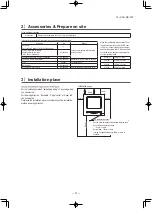
Accessories for outdoor unit
• Model name and power source • Refrigerant piping length • Piping, wiring and miscellaneous small parts • Indoor unit installation manual
Grommet (Heat pump type only)
Drain elbow (Heat pump type only)
Reducer set ø9.52 ø6.35
2
1
1
1
2
3
Check before installation work
Q’ty
INS
TALL
ATION MAN
UAL FOR OUTDOOR UNIT
2. REFRIGERANT PIPING WORK
1)
Restrictions
on
unit
installation
and
use
●
Check
the
following
points
in
light
of
the
indoor
unit
specifications
and
the
installation
site.
●
Obse
rve
the
following
restrictions
on
unit
installation
and
use.
Improper
installation
can
result
in
a
compressor
failure
or
pe
rformance
degradation
.
2)
Determination
of
pipe
size
●
Determine
refrigerant
pipe
size
pursuant
to
the
following
guidelines
based
on
the
indoor
unit
specifications.
Gas pipe
Liquid pipe
ø15.88
ø6.35
Flare
Flare
ø15.88
ø6.35
ø15.88
ø9.52
1. HAULAGE AND INSTALLATION
(T
ake particular care in car
rying in or moving the unit, and always pe
rform such an operation with two or more persons.)
Intake
The
height
of
a
wall
is
1200mm
or
less.
(
se
rvice
space
)
Intake
Outlet
Fasten
with
bolts
(M10-12)
Use
a
thicker
block
to
anchor
deepe
r.
Use
a
long
block
to
extend
the
width.
CAUTION
When
a
unit
is
hoisted
with
slings
for
haulage,
take
into
consideration
the
offset
of
its
gravity
center
position.
If
not
properly
balanced,
the
unit
can
be
thrown
off-balance
and
fall.
1)
Delivery
●
Deliver
the
unit
as
close
as
possible
to
the
installation
site
before
removing
it
from
the
packaging.
●
When
you
have
to
unpack
the
unit
for
a
compelling
reason
before
you
haul
it
to
the
installation
point,
hoist
the
unit
with
nylon
slings
or
ropes
and
protection
pads
so
that
you
may
not
damage
the
unit.
2)
Portage
●
The
right
hand
side
of
the
unit
as
viewed
from
the
front
(diffuser
side)
is
heavie
r.
A
person
car
rying
the
right
hand
side
must
take
heed
of
this
fact.
A
person
car
rying
the
left
hand
side
must
hold
with
his
right
hand
the
handle
provided
on
the
front
panel
of
the
unit
and
with
his
left
hand
the
corner
column
section
.
5)
Installation
space
●
W
alls surrounding the unit in the four sides are not acceptable.
●
There must be a 1-meter or larger space in the above.
●
When more than one unit are installed side by side, provide a 250mm or wider interval between them as a service space. In order to facilitate servicing of controls, please provide a sufficient space between units so that their top plates can be removed easily.
●
Where a danger of short-ci
rcuiting exists, install guide louvers.
●
When more than one unit are installed, provide sufficient intake space consciously so that short-ci
rcuiting may not occur
.
●
Where
piling
snow
can
bu
ry
the
outdoor
unit,
provide
proper
snow
guards.
L
3
L
2
L
4
L
1
Example installation
Size
●
In installing the unit, fix the unit
’s legs with bolts specified on the above.
●
The protrusion of an anchor bolt on the front side must be kept within 15 mm.
●
Securely install the unit so that it does not fall over during earthquakes or strong winds, etc.
●
Refer to the above illustrations for information regarding concrete foundations.
●
Install the unit in a level area. (With a gradient of 5 mm or less.) Im
pr
op
er
in
st
al
la
tio
n
ca
n
re
su
lt
in
a
co
m
pr
es
so
rf
ai
lu
re
, b
ro
ke
n
pi
pi
ng
w
ith
in
th
e
un
it
an
d
ab
no
rm
al
n
oi
se
g
en
er
at
io
n.
6)
Installation
L
H
Outdoor unit
Indoor unit
CAUTION
●
Th
e
us
e
re
st
ric
tio
ns
ap
pe
ar
in
g
in
th
e
ta
bl
e
ab
ov
e
ar
e
ap
pl
ica
bl
e
to
th
e
st
an
da
rd
pi
pe
siz
e
co
m
bi
na
tio
ns
sh
ow
n
in
th
e
ta
bl
e
be
lo
w.
W
he
re
an
ex
ist
in
g
pi
pe
s
ys
te
m
is
u
til
ize
d,
di
ffe
re
nt
o
ne
-w
ay
pi
pe
le
ng
th
re
st
ric
tio
ns
sh
ou
ld
a
pp
ly
de
pe
nd
in
g
on
it
s
pi
pe
siz
e.
Fo
r m
or
e
in
fo
rm
at
io
n,
p
lea
se
se
e
“5
. U
TI
LI
ZA
TI
ON
OF
E
XI
ST
IN
G
PI
PI
NG
.”
Outdoor unit connected
Refrigerant piping (branch pipe
L)
Indoor unit connected
About brazing
When pipe is brazing.
(2)
If
the
unit
can
be
affected
by
strong
wind,
following
measures
are
required.
Strong
wind
can
cause
damage
of
fan
(fan
motor),
or
can
cause
pe
rformance
degradation,
or
can
trigger
anomalous
stop
of
the
unit
due
to
rising
of
high
pressure.
3)
Refrigerant
pipe
wall
thickness
and
material
●
Select
refrigerant
pipes
of
the
table
shown
on
the
right
wall
thickness
and
material
as
specified
for
each
pipe
size.
Pipe diameter [mm]
Minimum pipe wall thickness [mm]
Pipe material*
ø6.35
0.8
O-type pipe
ø15.88
1.0
O-type pipe
*Phosphorus deoxidized seamless copper pipe ICS 23.040.15, ICS 77.150.30
NOTE
●
Select
pipes
having
a
wall
thickness
larger
than
the
specified
minimum
pipe
thickness.
He
avy
Pad
L1
L2
L3
L4
Open
300
100
250
Open
250
150
250
500
Open
100
250
(mm)
I
II
III
60
580
340
19
380
418
19
880
87.9
15
150
150
Intake
Outlet
①
Anchor bol tfixed position
②
Notabilia for installation
Plug the end of the pipe with tape, or other material, and fill the pipe with nitrogen gas.
Only use nitrogen gas (N
2
)
Taping
<
N
2
>
Nitrogen
Brazing
Station valve
Prima
ry side
Seconda
ry side
0.5MPa
Hand
Relief valve
Nitrogen
gas
Brazing
must
be
performed
under
a
nitrogen
gas
flo
w
.
Without
nitrogen
gas,
a
large
quantity
of
foreign
matters
(oxidized
film)
are
created,
causing
a
critical
failure
from
capilla
ry
tube
or
expansion
valve
clogging.
If the refrigerant is existing in the pipe at brazing, poisonous gas is produced.
Wind
direction
Wind
direction
Over
500
mm
2.Install the outlet air blow side of
the unit in a position perpendicular to the direction of wind.
3.
The
unit
should
be
installed
on
the
stable
and
level
foundation.
If
the
foundation
is
not
level,
the
down
the
unit
with
wires.
1.
Install the outlet air blow side of the unit to face a wall of building, or provide a fence or a windbreak screen.
7) To run the unit for a cooling operation,
when the outdoor temperature is –5°C or lower.
●
When the outdoor air temperature is –5°C or lower, provide a snow hood to the outdoor unit on site. So that strong wind will not blow against the outdoor heat exchanger directly.
4)
Caution
about
selection
of
installation
location
(1)
If
the
unit
is
installed
in
the
area
where
the
snow
will
accumulate,
following
measures
are
required.
The
bottom
plate
of
unit
and
intake,
outlet
may
be
blocked
by
sno
w
.
1
2
Provide
a
snow
hood
to
the
outdoor
unit
on
site.
3
Install
the
unit
under
eaves
or
provide
the
roof
on
site.
Since
drain
water
generated
by
defrost
control
may
freeze,
following
measures
are
required.
●
Don’t execute drain piping work
by using a drain elbow and drain grommets (accessories).
[Refer to DRAIN PIPING WORK.]
Install the unit on the base so that the bottom is higher than snow cover surface, and draining water is secured.
●
Attached heater on a base plate on site, if there is possibility to freeze drain water. In case that the product has a corrective drainage system, the drainage paths should have suitable threatment against freezing but be sure not to melt the material of drainage paths with heat.
30m
or less
20m
or less
20m
or less
L
H
H
Restrictions
Dimensional restrictions
Marks appearing in the drawing on the right
Main pipe length
Elevation difference between
Indoor unit
indoor and outdoor units
When the outdoor unit is positioned higher
FDT, FDE, FDU, FDUM, SRK
When the outdoor unit is positioned lower
3)
S
el
ec
tio
n
of
in
stalla
tio
n
lo
ca
tio
n
fo
r
th
e
ou
td
oo
r
un
it
Be
s
ur
e
to
sele
ct
a
s
ui
ta
ble
in
st
alla
tio
n
pla
ce
in
c
on
si
de
ra
tio
n
of
fo
llo
w
in
g
co
nd
iti
on
s.
〇
A
pla
ce
w
he
re
it
is
h
or
iz
on
ta
l,
st
ab
le
a
nd
c
an
e
nd
ur
e
th
e
un
it
w
ei
gh
t a
nd
wi
ll
no
t a
llo
w
v
ib
ra
tio
n
tr
an
sm
itt
an
ce
of
th
e
un
it.
〇
A
pla
ce
w
he
re
it
c
an
b
e
fr
ee
fr
om
p
os
si
bi
lit
y
of
b
ot
he
rin
g
ne
ig
hb
or
s
du
e
to
n
oi
se
o
r
ex
ha
us
t a
ir
fr
om
th
e
un
it.
〇
A
pla
ce
w
he
re
th
e
un
it
is
n
ot
e
xp
os
ed
to
o
il
sp
la
sh
es
.
〇
A
pla
ce
w
he
re
it
c
an
b
e
fr
ee
fr
om
d
an
ge
r
of
fl
am
m
ab
le
g
as
lea
ka
ge
.
〇
A
pla
ce
w
he
re
d
ra
in
w
at
er
c
an
b
e
di
sp
os
ed
w
ith
ou
t a
ny
tr
ou
bl
e.
〇
A
pla
ce
w
he
re
th
e
un
it
wil
l n
ot
b
e
af
fe
ct
ed
b
y
he
at
r
ad
ia
tio
n
fr
om
o
th
er
h
ea
t s
ou
rc
e.
〇
A
pla
ce
w
he
re
s
no
w
wil
l n
ot
a
cc
um
ul
at
e.
〇
A
pla
ce
w
he
re
th
e
un
it
ca
n
be
k
ep
t aw
ay
5
m
o
r
m
or
e
fr
om
T
V
se
t a
nd
/o
r
ra
di
o
recei
ve
r
in
o
rd
er
to
a
vo
id
a
ny
ra
di
o
or
T
V
in
te
rf
er
en
ce
.
〇
A
pla
ce
w
he
re
g
oo
d
ai
r
ci
rc
ula
tio
n
ca
n
be
s
ec
ur
ed
, a
nd
e
no
ug
h
se
rvi
ce
s
pa
ce
c
an
b
e
se
cu
re
d
fo
r
m
ai
nt
en
an
ce
an
d
se
rvic
e
of
th
e
un
it
sa
fe
ly
.
〇
A
pla
ce
w
he
re
th
e
un
it
wi
ll
no
t b
e
af
fect
ed
b
y
el
ec
tr
om
ag
net
ic
wav
es
a
nd
/o
r h
ig
h-
ha
rm
on
ic
wav
es
g
en
er
at
ed
b
y
ot
he
r
eq
ui
pm
en
t.
〇
A
pla
ce
w
he
re
c
hemic
al
s
ub
st
an
ce
s
lik
e
su
lfu
ric
g
as
, c
hl
or
ic
g
as
, a
ci
d
an
d
alka
li
(in
cl
ud
in
ga
m
m
on
ia
),
w
hi
ch
c
an
ha
rm
th
e
un
it,
wil
l n
ot
b
e
ge
ne
ra
te
d
an
d
no
t r
ema
in
.
〇
If
a
op
er
at
io
n
is
c
on
du
ct
ed
w
he
n
th
e
ou
td
oo
r
ai
r
te
m
pera
tu
re
is
-
5˚
C
lo
w
er
, t
he
o
ut
do
or
u
ni
t s
ho
ul
d
be
in
st
al
le
d
at
a
p
lace
w
he
re i
t i
s
no
t i
nfl
ue
nc
ed
b
y
na
tu
ral wi
nd
.
〇
A
pla
ce
w
he
re
s
tr
on
g
w
in
d wi
ll
no
t b
lo
w
a
ga
in
st
th
e
ou
tle
t a
ir
bl
ow
o
f t
he
u
ni
t.
D
o
no
t
in
st
al
l t
he
u
ni
t
in
p
lac
es
w
hi
ch
e
xp
os
ed
to
s
ea
b
ree
ze
(
e.
g.
c
oa
st
al
a
re
a)
o
r
cal
ci
um
c
hl
or
id
e
(e
.g
. s
no
w
mel
tin
g
ag
en
t)
, e
xp
os
ed
to
a
m
m
on
ia
su
bs
ta
nc
e
(e
.g
. o
rg
an
ic
fe
rt
ili
ze
r)
.
PSC012D137
Notabilia as a unit designed for R32
•
Read the “SAFETY PRECAUTIONS” ca
refully first of all and strictly follow it during the installation work in o
rder
to p
rotect yourself.
•
The p
recautionary items mentioned below a
re distinguished into two levels, and .
:
W
rong installation would cause serious consequences such as injuries or death.
:
W
rong installation might cause serious consequences depending on ci
rcumstances.
Both mentions the important items to p
rotect your health and safety so strictly follow them by any means.
•
Be su
re to confirm no anomaly on the equipment by commissioning after completed installation and explain the
operating methods as well as the maintenance methods of this eq
uipment to the user accor
ding to the owner
’s
manual.
•
Keep the installation manual together with owner
’s manual at a place whe
re any user can
read at any time.
Mo
reover if necessar
y, ask to hand them to a new use
r.
•
For installing qualified personnel, take p
recautions in
respect to themselves by using suitable p
rotective
clothing, g
roves, etc., and then perform the installation works.
•
Please pay attention not to fall down the tools, etc. when installing the unit at the high position.
•
If unusual noise can be hea
rd during operation, consult the deale
r.
•
The meanings of “Marks” used he
re a
re shown as follows:
•
This installation manual deals with outdoor units and general installation specifications onl
y. For indoor units,
refer to the
respective installation manuals supplied with the units.
•
When install the unit, be su
re to check whether the selection of installation place, power supply specifications, usage limitation (piping length, height di
ffe
rences between indoor and outdoor units, power
supply voltage and etc.) and installation spaces.
SAFETY PRECAUTION
S
Never do it under any ci
rcumstances.
Always do it acco
rding to the instruction.
CAUTION
W
ARNING
CAUTION
W
ARNING
W
ARNIN
G
CAUTION
•
Car
ry out the electrical work for ground lead with care.
Do not connect the ground lead to the gas line
, water line
, lightning conductor or telephone line
’s ground lead
. Incorrect grounding can cause unit faults such as electric shocks due to short-circuiting.
•
Ensure that no air enters in the refrigerant circuit when the unit is installed and rem
oved.
If
ai
r e
nt
ers i
n
th
e
re
fri
ge
ra
nt
ci
rc
ui
t,
th
e
pr
es
su
re
in
th
e
re
fri
ge
ra
nt
c
irc
ui
t
be
co
m
es
to
o hi
gh
, w
hi
ch
c
an
c
au
se
b
ur
st
a
nd
p
er
so
na
l in
ju
ry
.
•
Do
n
ot
pr
oc
es
si
ng
, s
pl
ic
e
th
e
po
w
er
c
or
d,
o
r s
ha
re
a
s
oc
ke
t w
ith
o
th
er
p
ow
er
p
lu
gs
.
This may cause fire or electric shock due to defecting contact
, defecting insulation
and ove
r-current etc.
•
Use the circuit breaker for all pole correct capacit
y.
Circuit breaker
should be the one that disconnect all poles under
over current.
Using the incorrect circuit breake
r, it can cause the unit malfunction and fire.
•
Install isolator or disconnect switch on the power supply wiring in accordance with the local codes and regulations.
The isolator should be locked in OFF state in accordance with EN60204-1.
•
Af
te
r m
ai
nt
en
an
ce
, all
w
iri
ng
, wi
rin
g
tie
s
an
d
th
e
lik
e,
s
ho
ul
d
be
re
tu
rn
ed
to
th
ei
r o
rig
in
al sta
te
a
nd
wi
rin
g
ro
ut
e,
a
nd
th
e
ne
ce
ss
ar
y
cl
ea
ra
nc
e f
ro
m
all
m
eta
l p
ar
ts
s
ho
ul
d
be
s
ec
ur
ed
.
•
Se
cu
re
a
sp
ac
e f
or
in
stallat
io
n,
in
sp
ec
tio
n
an
d
m
ain
te
na
nc
e
sp
ec
ifi
ed
in
th
e
m
an
ua
l.
Insufficient space can result in accident such as personal inju
ry due to falling
from the installation place.
•
Earth
le
ak
ag
e
bre
ak
er
m
ust
b
e
in
stal
le
d
If
th
e
ea
rth
le
ak
ag
e
br
eak
er is
no
t in
st
all
ed
, i
t c
an
c
au
se
fi
re
o
r e
le
ctr
ic
sh
oc
ks
.
•
Do
no
t i
nstall
th
e
un
it i
n
th
e
lo
cati
on
s lis
ted
be
lo
w
.
•
Lo
ca
tio
ns
w
he
re
ca
rb
on
fi
be
r,
m
et
al
pow
de
r o
r a
ny
p
ow
de
r is
flo
at
in
g.
•
Lo
ca
tio
ns
w
he
re
a
ny
subs
ta
nc
es
th
at
c
an
af
fe
ct
th
e un
it such
a
s sulphi
de
g
as
,
ch
lo
rid
e g
as
, a
cid an
d
al
ka
lin
e
ca
n
oc
cu
r.
•
Veh
ic
le
s
and shi
ps
.
•
Lo
ca
tio
ns
w
he
re
co
sm
et
ic o
r spe
ci
al sp
ra
ys
a
re
ofte
n u
sed
.
•
Lo
ca
tions
w
ith di
re
ct
ex
posu
re
o
f o
il mi
st
a
nd
st
ea
m su
ch
a
s k
itch
en a
nd
m
ach
in
e
pl
an
t.
•
Lo
ca
tions
w
he
re
a
ny
m
achines
w
hich ge
ne
ra
te
high
fr
eq
ue
ncy
h
ar
m
on
ic
s a
re
us
ed
.
•
Lo
ca
tio
ns
w
ith
sa
lty
a
tm
osph
er
es such
as
coa
st
lin
es
.
•
Lo
ca
tio
ns
w
ith
he
av
y sn
ow
(I
f in
st
all
ed
, b
e s
ure
to
p
ro
vide
ba
se
fr
am
e
and s
now
ho
od m
en
tio
ne
d i
n
th
e
m
an
ua
l).
•
Lo
ca
tio
ns
w
he
re
th
e uni
t is
e
xp
osed
to
chim
ney
s
m
ok
e.
•
Lo
ca
tions
at
high
a
lti
tud
e (m
or
e
th
an
100
0m hig
h)
.
•
Lo
ca
tio
ns
w
ith
a
m
m
oni
c
at
m
osp
he
re
s.
(e
.g
. o
rg
anic
fe
rtiliz
er
)
•
Lo
ca
tio
ns
w
ith
c
alcium chl
or
id
e (e
.g
. s
no
w
m
el
ting
a
ge
nt)
.
•
Lo
ca
tio
ns
w
he
re h
eat
ra
di
at
io
n
fro
m
o
ther h
eat
s
ou
rce
c
an
affe
ct
th
e un
it.
•
Lo
ca
tions
w
ith
ou
t g
oo
d
ai
r circu
la
tio
n.
•
Lo
ca
tio
ns
w
ith
a
ny
ob
st
acl
es
w
hich
ca
n pr
ev
en
t in
let
a
nd
o
ut
let
a
ir
of
th
e un
it.
•
Lo
ca
tio
ns
w
he
re s
ho
rt
circuit
of
a
ir
ca
n
occ
ur
(in
c
as
e
of
mu
ltip
le
un
its
instal
la
tio
n)
.
•
Lo
ca
tio
ns
w
he
re
st
ro
ng air b
low
s
ag
ains
t t
he
ai
r o
ut
let
of
o
ut
door
un
it.
•
Lo
ca
tions
w
he
re
s
om
et
hing
lo
ca
te
d
ab
ov
e
the un
it
co
uld
fal
l.
It
ca
n
ca
us
e
re
m
ar
ka
bl
e
de
cr
ea
se
in p
er
fo
rm
an
ce
, c
or
ro
si
on
a
nd
d
am
ag
e
of
co
m
po
nen
ts
, m
al
fu
nct
io
n
an
d
fir
e.
•
Installation must be carried out by the qualified installe
r.
If
you in
st
al
l t
he
s
ys
tem
by
y
ou
rs
el
f,
it
m
ay
c
au
se
s
er
io
us
tr
ou
bl
e su
ch
a
s
w
at
er
le
ak
s,
el
ec
tri
c s
ho
ck
s,
fi
re
a
nd
pe
rsonal in
ju
ry
, a
s
a
res
ul
t o
f a
s
ys
tem
m
al
fu
nc
tio
n.
D
o
no
t
ca
rry
o
ut
th
e ins
tall
at
io
n
and
m
ai
nt
ena
nc
e w
or
k
ex
cep
t b
y
th
e qu
ali
fie
d in
sta
lle
r.
•
Install the system in full accordance with the installation manual.
In
co
rre
ct in
st
al
la
tio
n
m
ay
c
aus
e
bu
rs
ts
, p
er
so
na
l in
ju
ry
, w
at
er
le
ak
s,
e
le
ct
ric
sh
oc
ks and fi
re
.
•
Be sure to use only for household and residence.
If
this app
lia
nc
e is ins
ta
lle
d in i
nf
er
io
r e
nv
iro
nm
en
t s
uc
h
as
m
ac
hi
ne
s
ho
p
an
d
et
c.
,
it
ca
n
ca
us
e
m
al
fu
nc
tio
n.
•
When installing in small rooms
, take prevention measures not to
exceed the density limit of refrigerant in the event of leakage
, referred
by the formula (accordance with ISO5149)
.
If the density of refrigerant exceeds the limit
, please consult the dealer and install the
ventilation system
, otherwise lack of oxygen can occu
r, which can cause serious accident.
•
Use the original accessories and the specified components for installation.
If parts other than those prescribed by us are used
, It may cause water leaks
,
electric shocks
, fire and personal inju
ry
.
•
Install the unit in a location with good support.
Unsuitable installation locations can cause the unit to fall and cause material
damage and personal inju
ry
.
•
Ensure the unit is stable when installed
, so that it can withstand
earthquakes and strong winds.
Unsuitable installation locations can cause the unit to fall and cause material
damage and personal inju
ry
.
•
Ve
ntila
te
th
e
w
or
ki
ng
a
re
a
w
ell in
th
e
ev
ent
o
f r
ef
rig
er
an
t l
ea
ka
ge
d
ur
in
g
in
stallati
on
.
If the refrigerant comes into contact with naked flames
, poisonous gas is produced.
•
Use the prescribed pipes
, fl
are nuts and tools for R32.
Using existing parts (for R22 or R407C) can cause the unit failure and serious
accidents due to burst of the refrigerant circuit.
•
Tighten the
flare nut by to
rque wrench with specified method.
If the flare nut were tightened with excess torque
, this may cause burst and
refrigerant leakage after a long period.
•
Do not open the se
rvice
valves for liquid line and gas line until completed
refrigerant piping work
, air tightness test and e
vacuation.
If the compressor is operated in state of opening se
rvice valves before completed
connection of refrigerant piping work
, you may incur frost bite or inju
ry from an
abrupt refrigerant outflow and air can be sucked into refrigeran
t circuit
, which can
cause burst or personal inju
ry due to anomalously high pressure in the refrigerant.
•
Th
e
el
ec
tr
ic
al
in
stalla
tio
n
m
us
t b
e
ca
rr
ie
d
ou
t b
y
th
e
qu
al
ifi
ed
e
le
ct
ric
ia
n
in
a
cc
or
da
nc
e wi
th
“
th
e
no
rm
fo
r e
le
ct
ric
al
w
or
k”
a
nd
“
nat
io
na
l w
iri
ng
re
gu
lat
io
n”
, a
nd
th
e sy
st
em
m
ust
b
e
co
nn
ec
te
d
to
th
e
de
di
ca
te
d
ci
rcu
it.
Power supply with insufficient capacity and incorrect function done by improper work can cause electric shocks and fire.
•
Be sure to shut off the power before starting electrical work.
Failure to shut off the power can cause electric shocks
, unit failure or incorrect
function of equipment.
•
Be sure to use the cables conformed to safety standard and cable ampacity for power distribution work
.
Unconformable cables can cause electric leak
, anomalous heat production or fire
.
•
This appliance must be connected to main power supply by means of a circuit breaker or switch (fuse:20A) with a contact separation of at least 3mm
.
•
Arrange the wiring in the control box so that it cannot be pushed up further into the box
. Install the se
rvice panel correctl
y.
Incorrect installation may result in overheating and fire.
•
Use the prescribed cables for electrical connection
, tighten the cables
securely in terminal block and relieve the cables correctly to prevent overloading the terminal blocks.
Lo
os
e
co
nn
ec
tio
ns
o
r c
ab
le
m
ou
nt
ings
c
an
c
au
se
a
no
m
al
ous
he
at
p
ro
du
ct
io
n
or
fi
re
.
•
Be sure to fix up the se
rvice panels.
Incorrect fixing can cause electric shocks or fire due to intrusion of dust or wate
r.
•
Be sure to switch off the power supply in the event of installation
,
inspection or se
rvicing.
If the power supply is not shut off
, there is a risk of electric shocks
, unit failure or
personal inju
ry due to the unexpected start of fan.
•
Stop the compressor before rem
oving the pipe after shutting the
se
rvice
valve on pump down work.
If the pipe is removed when the compressor is in operation with the se
rvice valve
open
, air would be mixed in the refrigeration circuit and it could cause explosion
and injuries due to abnormal high pressure in the cooling cycle.
•
Only use prescribed optional parts
. The installation must be carried out
by the qualified installe
r.
If you install the system by yourself
, it can cause serious trouble such as water
leaks
, electric shocks
, fire.
•
Be sure to wear protective goggles and gl
oves while at work.
•
Earth leakage breaker must be installed.
If the earth leakage breaker is not installed
, it can cause electric shocks.
•
After completed installation
, check that no refrigerant leaks from the
system.
If refrigerant leaks into the room and comes into contact with an oven or other hot
surface
, poisonous gas is produced.
•
Hang up the unit at the specified points with ropes which can su
pport the
weight in lifting for portage
. And to avoid jolting out of alignment
, be sure
to hang up the unit at 4-point support.
An improper manner of portage such as 3-point support can cause death or
serious personal inju
ry due to falling of the unit.
•
Consult the dealer or an
expert regarding rem
ov
al of the unit.
Incorrect installation can cause water leaks
, electric shocks or fire.
•
Do not perform brazing work in the airtight room.
It can cause lack of oxygen.
•
This unit is designed specifically for R32.
Using any other refrigerant can cause u
nit failure and personal inju
ry
.
•
Do not bundling
, winding or processing for the power cord
. O
r, do not
deforming the power plug due to tread it.
This may cause fire or heating.
•
Do not run the unit with rem
oved panels or protections.
Touching rotating equipments
, hot surfaces or high voltage parts can cause
personal inju
ry due to entrapment
, burn or electric shocks.
•
Do not perform a
ny change of protective device itself or its setup condition.
The forced operation by short-circuiting protective device of pressure switch and
temperature controller or the use of non specified component can cause fire or burst.
•
Do not perform a
ny repairs or modifications by yourself
. Consult the dealer
if the unit requires repai
r.
If you repair or modify the unit
, it can cause water leaks
, electric shocks or fire.
•
Take care when car
rying the unit by hand.
If the unit weights more than 20kg
, it must be carried by two or more persons
. Do
not car
ry by the plastic straps
, always use the car
ry handle when car
rying the unit
by hand
. Use gloves to minimize the risk of cuts by the aluminum fins.
•
Dispose of a
ny packing materials correctl
y.
Any remaining packing materials can cause personal inju
ry
. T
o avoid danger of
suffocation
, be sure to keep the plastic wrapper away from children and to
dispose after tear it up.
•
Be sure to insulate the refrigerant pipes so as not to condense the ambient air moisture on them.
Ins
uf
fic
ie
nt insu
la
tio
n
ca
n
ca
us
e
cond
ens
at
io
n,
which
c
an
le
ad
to
mo
is
tu
re
da
m
ag
e
on the
ce
ili
ng
, fl
oo
r, fu
rniture
and a
ny
o
th
er
v
al
ua
bl
es
.
•
Be s
ur
e
to
p
er
fo
rm air t
ig
ht
ness test
by
press
ur
iz
in
g
w
ith
n
itr
og
en
g
as
after
c
om
plet
ed
refr
ig
eran
t p
ip
in
g
w
or
k.
If the density of refrigerant exceeds the limit in the event of refrigerant leakage in
the small room
, lack of oxygen can occu
r, which can cause serious accidents.
•
Do
no
t i
nstall t
he
o
ut
do
or
un
it i
n
th
e lo
cat
io
ns lis
ted
b
el
ow
.
•
L
oc
at
io
ns
w
he
re
discha
rg
ed
hot
air o
r o
pe
ra
ting sound
of
th
e ou
td
oo
r unit c
an
bot
he
r n
eigh
bo
rh
oo
d.
•
L
oc
at
io
ns
w
he
re
ou
tle
t air
of
th
e
ou
td
oor un
it bl
ow
s dir
ect
ly
to
a
n
ani
m
al
or
pl
an
ts
. Th
e
ou
tle
t a
ir
can
af
fe
ct
a
dv
er
sel
y
to
th
e pl
an
t e
tc
.
•
L
oc
at
io
ns
w
he
re
vib
rat
ion
can b
e
amplified
and
tr
ansm
itt
ed due
to
insu
ffi
ci
en
t
st
re
ng
th
o
f s
tru
ct
ur
e.
•
L
oc
at
io
ns wh
er
e
vib
ra
tio
n
and op
er
at
io
n sound g
en
er
at
ed b
y
th
e ou
tdo
or
un
it
can
af
fe
ct
s
er
io
us
ly (
on
th
e w
all
o
r a
t t
he
pl
ace
ne
ar
bed
ro
om
).
•
L
oc
at
io
ns
w
he
re
an
e
quipme
nt
af
fe
ct
ed by high h
ar
m
onics is p
la
ce
d (TV s
et
o
r
ra
dio
re
ce
ive
r is p
la
ce
d
w
ithin
5
m
).
•
L
oc
at
io
ns
w
he
re
d
ra
in
ag
e
ca
nn
ot
run
of
f s
af
el
y.
It ca
n
af
fe
ct
sur
ro
undin
g
en
vir
on
m
en
t a
nd
c
aus
e
a
cl
ai
m
.
•
Do
no
t i
nstall
the
u
nit
ne
ar
th
e l
oc
ati
on
w
he
re
le
ak
ag
e
of
co
mb
ust
ib
le
gase
s
ca
n
oc
cu
r.
If
le
aked
g
ases accumu
la
te a
ro
und
the un
it,
it
c
an
c
aus
e
fir
e.
•
Do
n
ot install th
e
uni
t w
her
e
co
rr
osiv
e
gas (
su
ch as s
ulf
ur
ous
ac
id gas
etc
.)
or
c
om
bu
stibl
e
gas (
su
ch as t
hi
nn
er a
nd
p
et
ro
le
um
g
ases)
ca
n accum
ula
te
or
c
olle
ct
, o
r w
here
v
olatile
co
m
bus
tib
le
su
bst
an
ces are h
an
dl
ed
.
Co
rr
os
ive
g
as
c
an
c
au
se
c
or
ro
si
on
o
f h
ea
t e
xc
ha
ng
er
, b
re
ak
ag
e
of
p
la
st
ic
p
ar
ts
an
d
et
c.
A
nd
c
ombustib
le
g
as
c
an ca
us
e
fir
e.
•
Do
no
t i
nstall
no
r u
se
th
e syst
em
clo
se
to
the
equ
ipme
nt
th
at g
en
er
at
es
el
ec
tr
oma
gn
et
ic
fi
el
ds
or
h
ig
h f
re
quen
cy
h
arm
on
ic
s.
Equipme
nt
such
a
s i
nv
er
te
rs
, s
tand
by
ge
ne
ra
to
rs
, medical high
freque
ncy
equipme
nt
s and
te
le
communic
at
io
n
equip
m
en
ts can
aff
ec
t t
he
s
ys
te
m
, a
nd
c
au
se
m
al
fun
ct
io
ns
and b
re
akdo
wn
s.
The sy
ste
m can
also
af
fe
ct
m
edi
cal equipment
an
d
te
le
communic
at
io
n equipme
nt
, and
o
bs
tru
ct
it
s
fun
ct
io
n
or caus
e jammi
ng
.
•
Se
cur
e a
sp
ac
e f
or
in
stallat
ion
, i
ns
pec
tion
a
nd
m
ai
nt
en
an
ce
s
pe
cifi
ed
in
the
m
anu
al
.
In
su
ffi
ci
en
t sp
ac
e
can
re
su
lt in accide
nt
suc
h
as
pe
rsonal in
ju
ry
du
e to
fa
lling
fr
om
th
e i
ns
ta
llat
io
n pl
ac
e.
•
D
o
no
t install
th
e
ou
td
oo
r u
nit in a
lo
ca
tio
n
w
he
re i
ns
ects
a
nd
sm
al
l
animals c
an
in
ha
bi
t.
Ins
ec
ts and small an
im
al
s
can en
te
r the e
le
ct
ric
p
art
s an
d
cause damage or
fi
re
.
In
st
ru
ct
th
e us
er
to
ke
ep
the
su
rro
unding
s
cl
ea
n.
•
D
o
no
t u
se the base fra
m
e
fo
r o
ut
do
or
u
nit
w
hi
ch
is
c
or
ro
de
d
or
d
am
ag
ed
du
e
to
lo
ng
p
er
io
ds
o
f o
pe
ra
tio
n.
Using an old and da
m
age bas
e
frame
c
an
c
aus
e
th
e u
ni
t f
alling d
ow
n and c
au
se
pe
rs
onal in
ju
ry
.
•
D
o
no
t u
se
a
ny ma
te
rial
s
ot
he
r t
ha
n a
fu
se
w
ith
th
e
co
rr
ect rat
in
g in t
he
lo
cat
io
n
w
he
re
fu
se
s a
re
to
b
e
us
ed.
Conn
ec
ting
th
e
ci
rc
ui
t w
ith
c
op
pe
r wi
re
o
r o
th
er
m
et
al
th
re
ad
c
an
c
ause un
it
fai
lu
re and
fi
re
.
•
D
o
no
t t
ou
ch
a
ny
b
ut
to
ns
w
ith
w
et h
an
ds
.
It
ca
n
cau
se
el
ec
tric s
ho
cks
.
•
D
o
no
t t
ou
ch
a
ny
re
fr
ig
er
an
t p
ip
es
w
ith
y
ou
r h
an
ds
w
he
n
th
e sys
te
m
is
in
op
era
tio
n.
Du
ring op
er
at
ion
the
re
frige
rant pi
pe
s b
ec
ome e
xt
re
mely
ho
t o
r e
xt
re
m
el
y
co
ld
de
pe
ndin
g
th
e
op
er
atin
g
cond
iti
on
, a
nd i
t c
an
c
au
se
burn in
ju
ry
o
r f
ro
st
in
ju
ry
.
•
Do
no
t t
ou
ch
th
e su
ct
io
n
or al
um
in
um fi
n
on
th
e
ou
td
oo
r u
ni
t.
This
m
ay
c
ause in
ju
ry
.
•
D
o
no
t p
ut
a
ny
th
in
g
on t
he
ou
td
oo
r u
nit
a
nd
o
pe
ra
tin
g
un
it.
This
m
ay
c
ause
d
am
ag
e
th
e
ob
je
cts
or
in
ju
ry due
to
fa
llin
g
to
th
e
ob
je
ct.
•
D
o
no
t u
se
th
e
unit
fo
r s
pe
cial
p
ur
po
ses
su
ch as s
to
rin
g
food
s,
co
ol
in
g
pr
ec
is
io
n inst
ru
m
en
ts
an
d
pr
es
er
va
tio
n
of
a
ni
m
al
s,
p
la
nt
s
or
art
.
•
D
o
no
t c
le
an
u
p
th
e
un
it
w
ith
w
at
er
.
•
D
o
no
t s
te
p
on
to
th
e
ou
td
oo
r u
ni
t.
•
W
he
n
th
e
ou
tdo
or
u
nit is
in
stal
le
d
on
a
ro
of
o
r a
hi
gh
p
la
ce
, p
ro
vi
de
pe
rma
ne
nt l
ad
de
rs
an
d
ha
nd
rails
al
on
g
th
e
ac
ce
ss
ro
ute
a
nd
fe
nc
es
ha
nd
rails
ar
ou
nd
th
e
ou
td
oo
r un
it.
Inverter
driven
split
P
AC
90,
100VNP
Designed
for
R32
refrigerant
a
)
b
)
c
)
d
)
e
)
f
)
g
)
h
)
Gauge manifold
Charge hose
Electronic scale for refrigerant charging
Torque wrench
Flare tool
Protrusion control copper pipe gauge
Vacuum pump adapter
Gas leak detector
Dedicated R32 tools
●
Do not use any refrigerant other than R32.
R32 will rise to pressure about 1.6 times higher than that of a conventional refrigerant (R22 or
R407C). A cylinder containing R32 has a lightblue indication mark on the top.
●
A unit designed for R32 has adopted a different size indoor unit service valve charge port and a different size check joint p
rovided in the unit
to prevent the charging of a wrong refrigerant by mistake. The processed dimension of the flared part of a refrigerant pipe and a flare nut's parallel side measurement have also been alter
ed to raise
strength against pressure. Accordingly, you are required to arrange dedicated R32 tools listed in the table on the next page before installing or servicin
g this unit.
●
All indoor units must be models designed exclusively for R32. Check connectable indoor unit models in a catalog, etc. (A wrong
in door unit,
if connected into the system, will impair proper system operation)
Accessories for outdoor unit
• Model name and power source • Refrigerant piping length • Piping, wiring and miscellaneous small parts • Indoor unit installation manual
Grommet (Heat pump type only)
Drain elbow (Heat pump type only)
Reducer set ø9.52 ø6.35
2
1
1
Check before installation work
Q’ty
201907
①
②
③
- 92 -

