-
115
-
'19 • PAC-SM-334
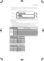
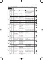
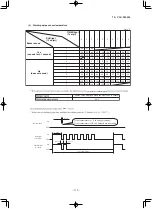
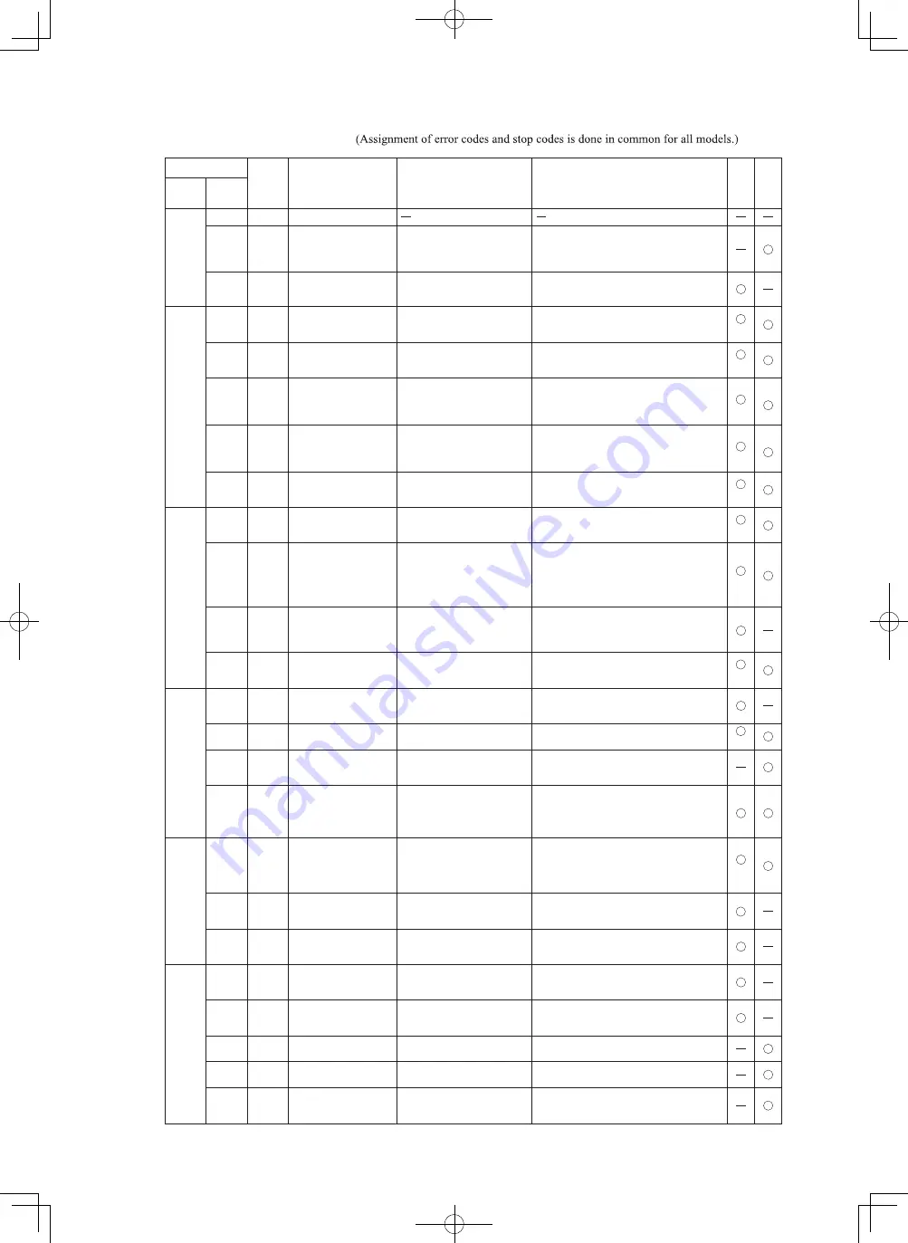
(c) Error code, stop code table
0
Normal
Can not receive signals for 35
seconds
(if communications have recovered)
Power source is faulty.
Power source cables and signal lines are improperly wired.
Cooling overload operation.
Outdoor unit fan speed drops.
Outdoor heat exchanger sensor is short-circuit.
Refrigerant is insufficient.
Discharge pipe sensor is faulty.
Service valve is closed.
Outdoor air temperature sensor wire is
disconnected.
Connector connections are poor.
Discharge pipe sensor wire is
disconnected.
Connector connections are poor.
Compressor lock.
Compressor wiring short-circuit.
Compressor output is open phase.
Service valve is closed.
Electronic expansion valve is faulty.
Compressor is faulty.
Outdoor fan motor is faulty.
Connector connections are poor.
Power transistor is damaged.
Service valve is closed.
Refrigerant is insufficient.
Refrigerant is overcharge.
Compressor lock.
Overload operation.
Compressor wiring is disconnected.
Power transistor is damaged.
Power source construction is defective.
Compressor is faulty.
Compressor is faulty.
Compressor output is open phase.
Electronic expansion valve is faulty.
Overload operation.
Connection lines are faulty.
Noise is causing faulty operation.
Indoor fan motor is faulty.
Connector connections are poor.
Indoor heat exchanger sensor wire is
disconnected.
Connector connections are poor.
High humidity condition.
Humidity sensor is faulty.
Indoor unit fan speed drops.
Indoor heat exchanger sensor is broken wire.
Heating overload operation.
Indoor unit fan speed drops.
Indoor heat exchanger sensor is short-circuit.
Anti-condensation prevention control is operating.
Refrigeration cycle system
protective control
Anti-condensation control
Heating high pressure control
Short-circuit in the power
transistor (high side)
Current cut circuit breakdown
OFF
05
5-time
flash
1-time
flash
Cooling high pressure control
35
5-time
flash
51
1-time
flash
Indoor unit's fan motor is
abnormal
80
OFF
Current cut
42
2-time
flash
V
Compressor wiring is unconnection
oltage drop
Low speed protective control
59
9-time
flash
Compressor overheat 115°C
36
6-time
flash
Outdoor heat exchanger sensor wire is
disconnected.
Connector connections are poor.
Outdoor unit PCB is faulty.
Outdoor heat exchanger sensor
is abnormal
37
7-time
flash
Indoor heat exchanger sensor
is abnormal (anomalous stop)
82
2-time
flash
86
6-time
flash
Anti-frost control
85
5-time
flash
7-time
flash
57
7-time
flash
84
4-time
flash
Outdoor air temperature sensor
is abnormal
38
8-time
flash
Outdoor unit's fan motor is
abnormal
48
8-time
flash
Current safe
58
8-time
flash
Connection lines between the
indoor and outdoor units are
faulty
61
1-time
flash
Serial transmission error
62
2-time
flash
Discharge pipe sensor is
abnormal (anomalous stop)
39
9-time
flash
Rotor lock
60
OFF
(5 times)
(3 times)
(3 times)
(3 times)
(2 times)
Number of flashes when in
service mode
RUN
light
(10's digit)
TIMER
light
(1's digit)
Stop coad
or
Error coad
Error content
Cause
Occurrence conditions
Error
display
Auto
recovery
OFF
3-time
flash
5-time
flash
6-time
flash
8-time
flash
4-time
flash
(2 times)
(2 times)
(3 times)
(3 times)
When high pressure control operates during heating
operation and the compressor stops.
When the anti-frost control operates and the compressor
stops during cooling operation.
When 10 seconds passes after the power is turned on
without communications signals from the indoor or
outdoor unit being detected correctly.
When the current is 1A or less at the time the
compressor started.
When the power source voltage drops during operation.
When the compressor command speed is 1ower than 32
rps for 60 minutes.
When a temperature of –28°C or lower is sensed
continuously for 40 minutes during heating operation.
(the compressor stops).
When the indoor fan motor is detected to be running
at 300 min
-1
or lower speed with the fan motor in the ON
condition while the air-conditioner is running.
When 7 minutes 35 seconds passes without
communications signals from either the outdoor unit or
the indoor unit being detected correctly.
After the compressor starts, when the compressor stops
due to rotor lock.
When there is a current safe stop during operation.
When it is judged that the power transistor was
damaged at the time the compressor started.
When a fan speed of 75 min
-1
or lower continues for 30
seconds or longer.
When refrigeration cycle system protective control
operates.
Error is displayed if the converter voltage exceeds target voltage
(3 times within 20 minutes). Remote control may be set after
3-minute delay. Error is displayed if the converter voltage is
lower than 210V (1-time within 5 seconds after power ON).
In order to prevent from overcurrent of inverter, if the
current exceeds the specifications, it makes the compressor
stopping.
When 35 seconds passes without
communications signals from either the outdoor unit or
the indoor unit being detected correctly.
Error of wired remote control
wiring
01
–55°C or lower is detected for 5 seconds continuously 3 times
within 40 minutes after intial detection of this anomalous temperature.
Or–55°C lower is detected for 5 seconds continuously
within 20 seconds after power ON.
–55°C or lower is detected for 5 seconds continuously 3 times
within 40 minutes after intial detection of this anomalous temperature.
Or–55°C lower is detected for 5 seconds continuously
within 20 seconds after power ON.
–25°C or lower is detected for 5 seconds continuously 3 times
Service valve (gas side) closed
Outdoor unit PCB is faulty.
Service valve (gas side)
closed operation
40
OFF
(2 times)
If the inverter output current value exceeds the setting value
within 80 seconds after the compressor ON in the heating
mode, the compressor stops.
within 40 minutes after intial detection of this anomalous
temperature.
When the discharge pipe sensor's value exceeds the set
value.
When the outdoor heat exchanger sensor's value exceeds
the set value.
The wired remote control wire Y is open. The wired remote
control wires X and Y are reversely connected. Noise is
penetrating the wired remote control lines. The wired
remote control or indoor unit PCB is faulty.
Broken wired remote control wire,
defective indoor unit PCB
Defective active filter.
Active filter voltage error
47
Indoor or outdoor unit PCB are faulty.
Outdoor unit PCB is faulty.
Outdoor unit PCB is faulty.
Outdoor unit PCB is faulty.
Outdoor unit PCB is faulty.
Outdoor unit PCB is faulty.
Outdoor unit PCB is faulty.
Outdoor unit PCB is faulty.
Indoor or outdoor unit PCB are faulty.
Indoor or outdoor unit PCB are faulty.
Indoor unit PCB is faulty.

