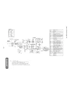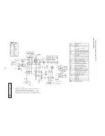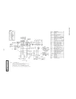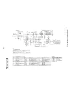
-
103
-
Exchange the inverter pwb according to the following procedure.
1. Exchange the pwb
after elapsing 3 minutes from power OFF.
(Be sure to measure voltage (DC) of two places
(1. Power supply for pwb 2. Power supply for fan motor) and
check that the voltage is discharged sufficiently.
(Refer to Fig.3 next page))
2. Disconnect the connectors from the pwb.
3. Exchange the pwb.
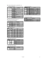
4. Match the setting switches (JSW10, 11) with the former pwb. (Refer to Table.1)
5. Connect the connectors, wiring, and snubber capacitor. (Contirm the
connectors are not half inserted.
)
6. Cautions for maintenance of the control box
This control box has its front part hinged so as to be able to open and close for maintenance of the inverter.
Following cautions must be observed during the maintenance.
Always follow the instructions described in the technical manual when implementing the maintenance.
(1) Turn off the power supply before starting the maintenance.
(2) After waiting for minimum 3 minutes after turning off the main power supply, measure the DC power supply voltage
(between F1 and DS (-) of the control power supply) to confirm according to the technical manual that the electricity
has been discharged sufficiently.
Only then disconnect the power supply cable and the signal cable from the terminal board.
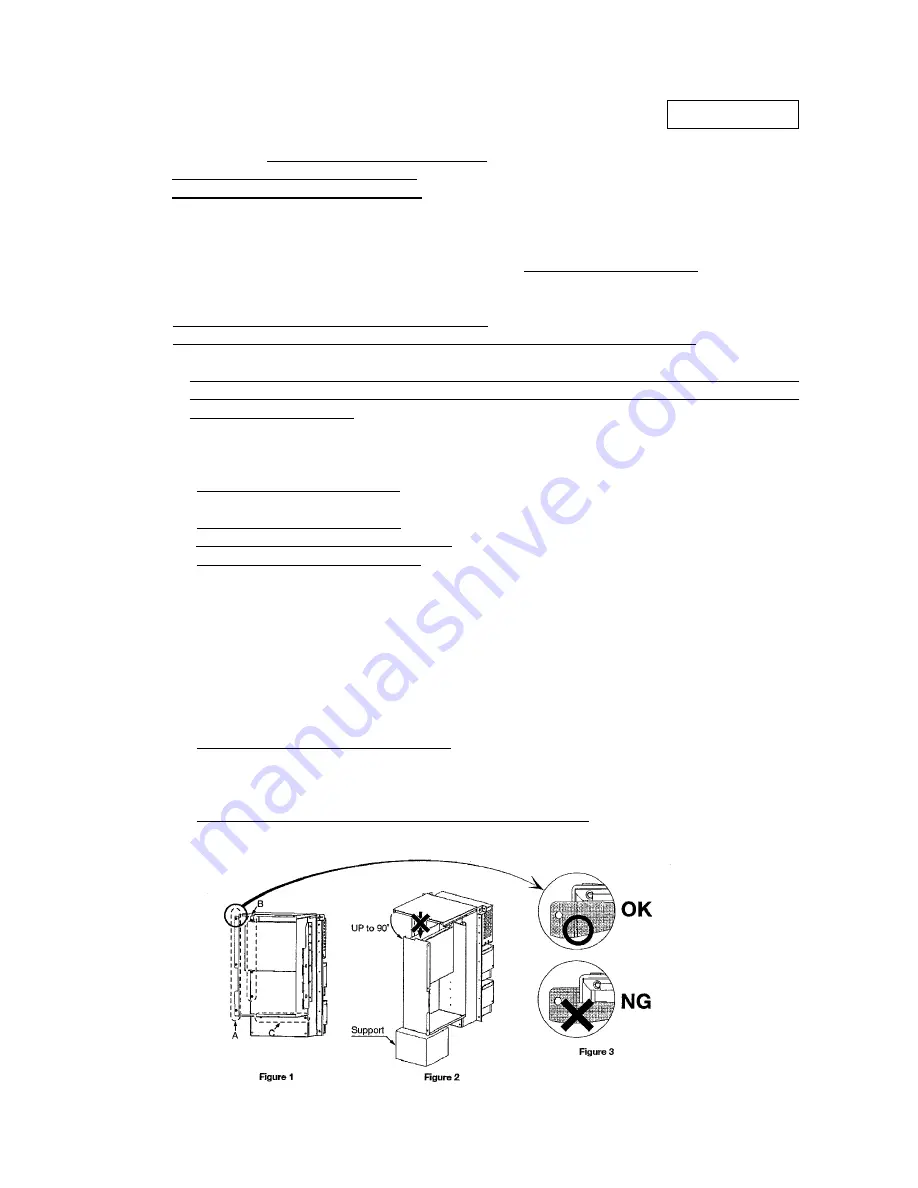
(3) Remove a total 8 pieces of screw at the sections A, B and C in Figure 1.
• Take care not to drop screws on the PCB, etc. when removing them.
• Make sure to collect when dropped any.
(4) Open the front part of the control box as shown in Figure 2.
• Don’t open the front part more than 90º.
• Avoid exerting undue force on the open front part.
• Provide a support under the open fuont part.
(5) After opening the front part of the control box, you can access to the inverter. Start the maintenance according to the tech-
nical manual.
• When a tie wrap band has been cut off, fix it firmly at the original position with a new tie wrap band.
• When a connector has been disconnected from the PCB, insert firmly the connector again at the original position.
• Some of electrical parts are designed specifically to INV1 or INV2.
They are stamped or indicated with the lead mark to which of INV1 or INV2 they are used.
Take care not to use wrong parts duing repair.
If wrong parts are used, the equipment will not operate properly.
(6) When the maintenance is over, close the front part of the control box as shown in Figure 3.
• Take care not to nip the wiring with the front part.
(7) Reinstall and tighten the 8 screws removed at the sections A, B and C.
Don’t overlook to tighten the screws at the sectiong B particularly.
• Take care not to drop screws on the PCB, etc. when tightening them.
• Make sure to collect when dropped any, and tighten them at proper positions.
(8) Confirm visually that all screws have been tightened, and all cables have been connected properly.
pcb012d018ab
2.5 Inverter PCB replacement procedure
Summary of Contents for FDE112KXE6A
Page 104: ... 102 ...
Page 111: ... 108 b Ceiling cassette 4 way Compact type FDTC Models All moddels B PJA003Z331 ...
Page 112: ... 109 c Ceiling cassette 2 way type FDTW Models FDTW28KXE6 45KXE6 56KXE6 B PJB001Z560 ...
Page 113: ... 110 Models FDTW71KXE6 90KXE6 B PJB001Z561 ...
Page 114: ... 111 Models FDTW112KXE6 140KXE6 B PJB001Z562 ...
Page 115: ... 112 d Ceiling cassette 1 way type FDTS Model FDTS45KXE6 A PJC001Z195 ...
Page 116: ... 113 Model FDTS71KXE6 A PJC001Z196 ...
Page 117: ... 114 e Ceiling cassette 1 way compact type FDTQ Models All models A PJC001Z190 ...
Page 118: ... 115 Models All models Duct panel A PJC001Z240 ...
Page 121: ... 118 Models FDU224KXE6 280KXE6 B PJD001Z230 ...
Page 123: ... 120 Models FDUM112KXE6 140KXE6 B PJR002Z259 ...
Page 124: ... 121 h Duct connected Ultra thin Low static pressure type FDQS Models All models C PJC001Z200 ...
Page 125: ... 122 i Wall mounted type FDK Models FDK22KXE6 28KXE6 36KXE6 45KXE6 56KXE6 B PHA000Z983 ...
Page 126: ... 123 Models FDK71KXE6 B PHA000Z984 ...
Page 127: ... 124 j Ceiling suspended type FDE Models FDE36KXE6A 45KXE6A 56KXE6A B PFA003Z826 ...
Page 128: ... 125 Models FDE71KXE6A 112KXE6A 140KXE6A B PFA003Z827 ...
Page 129: ... 126 k Floor standing with casing type FDFL Models All models B PGD000Z053 ...
Page 130: ... 127 l Floor standing without casing type FDFU Models All models A PGD000Z058 ...
Page 131: ... 128 m Duct Connected Compact and Flexible type FDUH Models All models A PJC001Z255 ...
Page 138: ... 135 ...
Page 139: ... 136 ...
Page 143: ... 140 b ...
Page 144: ... 141 ...
Page 191: ... 188 5 4 Installation of outdoor unit ...
Page 193: ... 190 ...
Page 194: ... 191 ...
Page 195: ... 192 ...
Page 196: ... 193 ...
Page 197: ... 194 ...
Page 198: ... 195 ...
Page 199: ... 196 ...
Page 200: ... 197 ...
Page 201: ... 198 ...
Page 202: ... 199 ...
Page 203: ... 200 ...
Page 204: ... 201 ...
Page 205: ... 202 ...
Page 206: ... 203 ...
Page 207: ... 204 ...
Page 208: ... 205 ...
Page 210: ... 207 ...
Page 211: ... 208 ...
Page 212: ... 209 ...
Page 215: ... 212 2 model type DIS model type HEAD ...
Page 216: ... 213 2 2 ...
Page 217: ... 214 2 2 2 2 2 ...

