-
11
-
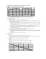
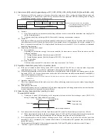
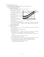
(3) Starting control of the compressor (Master unit/Slave unit)
According to the elapsed time after power ON and to the number of start-up, the starting control method of compressor is
shown in following table. However during the defrost control, oil return control and oil equalization control, the starting control
method of compressor is depended on that of the each control.
(a) 4-way valve switching safeguard (Master unit/Slave unit)
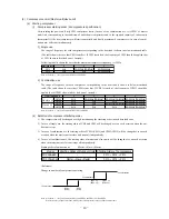
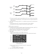
At starting, the inverter compressor (CM1, CM2) is operated under following conditions regardless of the decision frequency.
(i)
0-20Hz operation
It is operated in the range of 0-20Hz. However during this operation, the compressor protective controls like current safe
control, high pressure control, discharge pipe temperature control, low pressure control, power transistor temperature control,
under-dome temperature control and compression ratio protective control are not performed.
(ii) 25-40(48)Hz opearation
The maximum frequency is determined by the temperature detected with the outdoor air temperature thermistor (Tho-A).
1) In case of 0°C or lower of Tho-A: It starts to increase the frequency up to 48Hz as maximum frequency and
when the frequency reaches 48Hz, it stops.
2) In case of higher than 0°C of Tho-A: It starts to increase the frequency up to 40Hz as maximum frequency and.
when the frequency reaches 40Hz, it stops. However during this operation, if the starting conditions of the com
-
pressor protective controls like current safe control, high pressure control, discharge pipe temperature control,
low pressure control, power transistor temperature control, under-dome temperature control or compression ratio
protective control is satisfied, this control ends and it is controlled according to such protective control satisfied
with. And if the compressor frequency is determined and this protective control is cancelled, it returns to the nor
-
mal operation.
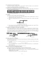
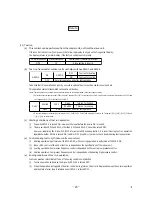
(b) Compressor protective start control (Master unit/Slave unit)
The compressor frequency is controlled regardless of the target frequency.
1) Up to 1minutes 45 seconds after the compressor starts, it is operated at 20Hz.
2) When 1minutes 45 seconds has elapsed after the compressor starts, it is operated at the frequency by compressor
potective start control.
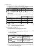
(c) Compressor protective start control "A" according to the crankcase heater ON time (Master unit/Slave
unit)
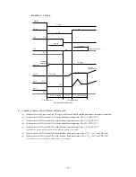
If it is the 1st startup after 45 minutes of the cumulative crankcase heater ON time has elapsed since power ON or if it is
the subsequent startup after the compressor has stopped for 45 minutes or more since power ON, it starts operation accord
-
ing to this control.
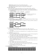
1) After 4-way valve switching safeguard, inverter frequency is set at 20Hz. And during reducing frequency to 20Hz
after 4-way valve switching safeguard, if the time for reaching to 20Hz is elasped 1 minutes after startup, it is set at
the maximum frequency after 1 minute elasped (20Hz+5Hz).
2) During the period of 15 minutes after the inverter frequency reaches to 10Hz (the frequency to complete startup), the
maximum inverter frequency will be increased from 20Hz by 5Hz per minute.
3) If the compressor stops within the period of 15 minutes after startup, and when the compressor starts again, the maxi
-
mum inverter frequency is increased from 20Hz by 5Hz per minute during the cumlative period of 15 minutes under
this control after the initial startup.
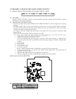
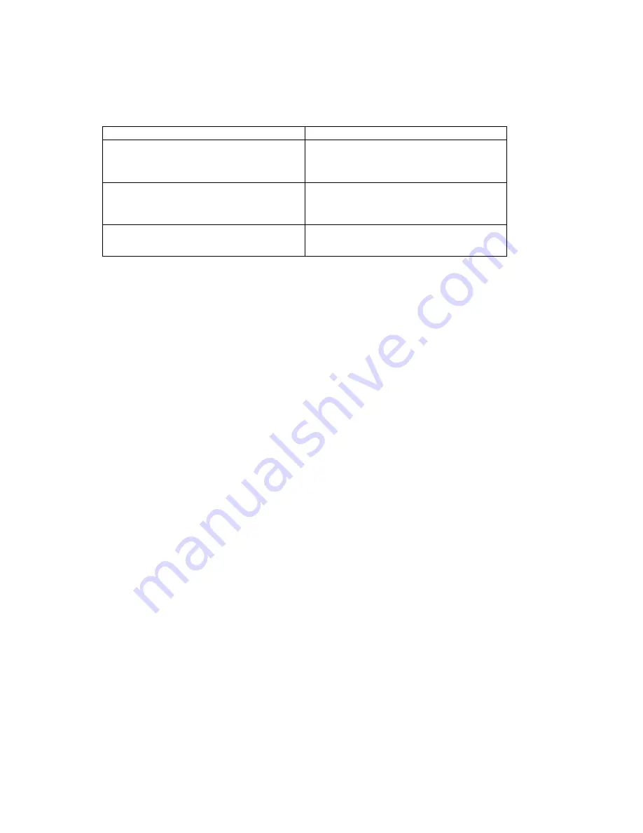
Conditions
Starting method
①
The 1st startup after 45minutes or more has elapsed since
power ON, or the subsequent startup after the
compressor has been stopping for 45 minutes or longer
with keeping the power ON.
After 4-way valve switching safeguard, "compressor
protective start control A" will be perfomed according to the
crankcase heater ON time. (See followings)
②
The 1st startup after less than 45 minutes has elasped
since power ON
After 4-way valve switching safeguard, "compressor
protective start control B" will be perfomed according to the
crankcase heater ON time. (See next page)
③
The startup other than
①
and
②
mentioned above.
After 4-way valve switching safeguard, "compressor
protective start controls" will be perfomed.
Summary of Contents for FDE112KXE6A
Page 104: ... 102 ...
Page 111: ... 108 b Ceiling cassette 4 way Compact type FDTC Models All moddels B PJA003Z331 ...
Page 112: ... 109 c Ceiling cassette 2 way type FDTW Models FDTW28KXE6 45KXE6 56KXE6 B PJB001Z560 ...
Page 113: ... 110 Models FDTW71KXE6 90KXE6 B PJB001Z561 ...
Page 114: ... 111 Models FDTW112KXE6 140KXE6 B PJB001Z562 ...
Page 115: ... 112 d Ceiling cassette 1 way type FDTS Model FDTS45KXE6 A PJC001Z195 ...
Page 116: ... 113 Model FDTS71KXE6 A PJC001Z196 ...
Page 117: ... 114 e Ceiling cassette 1 way compact type FDTQ Models All models A PJC001Z190 ...
Page 118: ... 115 Models All models Duct panel A PJC001Z240 ...
Page 121: ... 118 Models FDU224KXE6 280KXE6 B PJD001Z230 ...
Page 123: ... 120 Models FDUM112KXE6 140KXE6 B PJR002Z259 ...
Page 124: ... 121 h Duct connected Ultra thin Low static pressure type FDQS Models All models C PJC001Z200 ...
Page 125: ... 122 i Wall mounted type FDK Models FDK22KXE6 28KXE6 36KXE6 45KXE6 56KXE6 B PHA000Z983 ...
Page 126: ... 123 Models FDK71KXE6 B PHA000Z984 ...
Page 127: ... 124 j Ceiling suspended type FDE Models FDE36KXE6A 45KXE6A 56KXE6A B PFA003Z826 ...
Page 128: ... 125 Models FDE71KXE6A 112KXE6A 140KXE6A B PFA003Z827 ...
Page 129: ... 126 k Floor standing with casing type FDFL Models All models B PGD000Z053 ...
Page 130: ... 127 l Floor standing without casing type FDFU Models All models A PGD000Z058 ...
Page 131: ... 128 m Duct Connected Compact and Flexible type FDUH Models All models A PJC001Z255 ...
Page 138: ... 135 ...
Page 139: ... 136 ...
Page 143: ... 140 b ...
Page 144: ... 141 ...
Page 191: ... 188 5 4 Installation of outdoor unit ...
Page 193: ... 190 ...
Page 194: ... 191 ...
Page 195: ... 192 ...
Page 196: ... 193 ...
Page 197: ... 194 ...
Page 198: ... 195 ...
Page 199: ... 196 ...
Page 200: ... 197 ...
Page 201: ... 198 ...
Page 202: ... 199 ...
Page 203: ... 200 ...
Page 204: ... 201 ...
Page 205: ... 202 ...
Page 206: ... 203 ...
Page 207: ... 204 ...
Page 208: ... 205 ...
Page 210: ... 207 ...
Page 211: ... 208 ...
Page 212: ... 209 ...
Page 215: ... 212 2 model type DIS model type HEAD ...
Page 216: ... 213 2 2 ...
Page 217: ... 214 2 2 2 2 2 ...

