-
139
-
PJA012D756
A
Installation of indoor unit (continued)
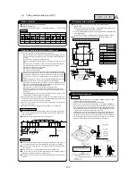
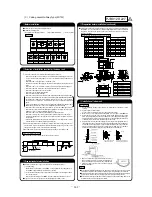
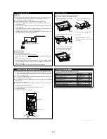
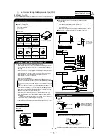
6. Make sure to install the indoor unit horizontally. Confi rm the
levelness of the indoor unit with a level gauge or transparent hose
fi lled with water. Keep the height difference at both ends of the
indoor unit within 3mm.
7. Tighten four upper nuts and fi x the unit after height and levelness
adjustment.
Caution
z
Do not adjust the height by adjusting upper nuts. It will cause unexpected stress on the indoor unit
and it will lead to deformation of the unit, failure of attaching a panel, and generating noise from the
fan.
z
Make sure to install the indoor unit horizontally and set the gap between the unit underside and
the ceiling plane properly. Improper installation may cause air leakage, dew condensation, water
leakage and noise.
z
Even after decorative panel attached, still the unit height can be adjusted fi nely. Refer to the
installation manual for decorative panel for details.
z
Make sure there is no gap between decoration panel and ceiling surface, and between decoration
panel and the indoor unit. The gap may cause air leakage, dew condensation and water leakage.
z
In case decorative panel is not installed at the same time, or ceiling material is installed after the
unit installed, put the cardboard template for installation attached on the package (packing material
of cardboard box) on the bottom of the unit in order to avoid dust coming into the indoor unit.
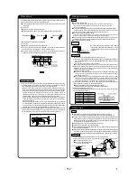
Refrigerant pipe
Caution
z
Use the new refrigerant pipe.
When re-using the existing pipe system for R22 or R407C, pay attention to the following items.
x
Change the fl are nuts with the attached ones (JIS category 2), and reprocess the fl are parts.
x
Do not use thin-walled pipes.
z
Use phosphorus deoxidized copper alloy seamless pipe (C1220T specifi ed in JIS H3300) for
refrigeration pipe installation.
In addition, make sure there is no damage both inside and outside of the pipe, and no harmful
substances such as sulfur, oxide, dust or a contaminant stuck on the pipes.
z
Do not use any refrigerant other than R410A.
Using other refrigerant except R410A (R22 etc.) may degrade inside refrigeration oil. And air getting
into refrigeration circuit may cause over-pressure and resultant it may result in bursting, etc.
z
Store the copper pipes indoors and seal the both end of them until they are brazed in order to avoid
any dust, dirt or water getting into pipe. Otherwise it will cause degradation of refrigeration oil and
compressor breakdown, etc.
z
Use special tools for R410 refrigerant.
Work procedure
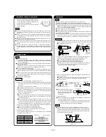
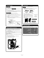
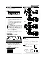
1. Remove the fl are nut and blind fl anges on the pipe of the indoor unit.
Make sure to loosen the fl are nut with holding the nut on pipe side with a spanner and giving
torque to the nut with another spanner in order to avoid unexpected stress to the copper pipe,
and then remove them.
(Gas may come out at this time, but it is not abnormal.)
z
Pay attention whether the fl are nut pops out. (as the indoor unit is sometimes pressured.)
2. Make a fl are on liquid pipe and gas pipe, and connect the refrigeration pipes on the indoor unit.
Bend the pipe with as big radius as possible and do not bend the pipe repeatedly. In addition, do
not twist and crush the pipes.
Do a fl are connection as follows:
z
Make sure to loosen the fl are nut with holding the nut on pipe side with a spanner and giving
torque to the nut with another spanner in order to avoid unexpected stress to the copper pipe,
and then remove them.
z
When fastening the fl are nut, align the refrigeration pipe with the center of fl are nut, screw the nut
for 3-4 times by hand and then tighten it by spanner with the specifi ed torque mentioned in the
table below. Make sure to hold the pipe on the indoor unit securely by a spanner when tightening
the nut in order to avoid unexpected stress on the copper pipe.
3. Cover the fl are connection part of the indoor unit with attached insulation material after a gas
leakage inspection, and tighten both ends with attached straps.
z
Make sure to insulate both gas pipes and liquid pipes completely.
Incomplete insulation may cause dew condensation or water dropping.
4. Refrigerant is charged in the outdoor unit.
As for the additional refrigerant charge for the indoor unit and piping, refer to the installation manual
attached to the outdoor unit.
Pipe diameter
Tightening torque N·m
I
6.35
14 to 18
I
9.52
34 to 42
I
12.7
49 to 61
I
15.88
68 to 82
I
19.05
100 to 120
Drain pipe (continued)
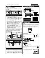
Work procedure
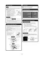
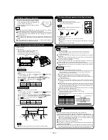
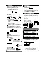
1. Insert the supplied drain hose (the end made of soft PVC) to the step of the drain socket on
the indoor unit and fi x it securely with the clamp.
z
Do not apply adhesives on this end.
Drain socket
The step part
Drain hose
No adhesive allowed
2. Prepare a joint for connecting VP-20 pipe, adhere and connect the joint to the drain hose (the end
made of rigid PVC), and adhere and connect VP-20 pipe (prepare on site).
As for drain pipe, apply VP-20 made of rigid PVC which is on the market.
z
Make sure that the adhesive will not get into the supplied drain hose.
It may cause the fl exible part broken after the adhesive is dried up and gets rigid.
z
The fl exible drain hose is intended to absorb a small difference at installation of the unit or drain
pipes. Intentional bending, expanding may cause the fl exible hose broken and water leakage.
3. Make sure to make descending slope of greater than 1/100 and do not make up-down bend and/or
trap in the midway.
z
Pay attention not to give stress on the pipe on the indoor unit side, and support and fi x the pipe
as close place to the unit as possible when connecting the drain pipe.
z
Do not set up air vent.
Supporting metal
No bump
No trap
Not touching the water
Trapped air will
generate noises.
Air vent
Insulation material
1.5m ~ 2m
Descending slope greater than 1/100
z
When sharing a drain pipe for more than one
unit, lay the main pipe 100mm below the drain
outlet of the unit. In addition, select VP-30 or
bigger size for main drain pipe.
4. Insulate the drain pipe.
z
Be sure to insulate the drain socket and rigid PVC pipe installed indoors otherwise it may cause
dew condensation and water leakage.
After drainage test implementation, cover the drain socket part with pipe cover (small size),
then use the pipe cover (big size) to cover the pipe cover (small size), clamps and part of the
drain hose, and fi x and wrap it with tapes to wrap and make joint part gapless.
Drain up
z
The position for drain pipe outlet can be raised up to 600mm above the ceiling. Use elbows for
installation to avoid obstacles inside ceiling. If the horizontal drain pipe is too long before vertical
pipe, the backfl ow of water will increase when the unit is stopped, and it may cause overfl ow of
water from the drain pan on the indoor unit. In order to avoid overfl ow, keep the horizontal pipe
length and offset of the pipe within the limit shown in the fi gure below.
Drain hose
600mm or less
Joint for VP-20
(Prepare on site)
295 to 325mm
100 or less
Drain test
z
After installation of drain pipe, make sure that drain system work in good condition and no water
leakage from joint and drain pan. Check if the motor sound of drain pump is normal or not.
z
Do drain test even if installation of heating season.
z
For new building cases, make sure to complete the test before
hanging the ceiling.
1. Pour water of about 1000cc into the drain pan in the indoor unit by
pump so as not to get the electrical component wet.
2. Make sure that water is drained out properly and there is no water
leakage from any joints of the drain pipe at the test.
Confi rm that the water is properly drained out while the drain motor is
operating. At the drain socket (transparent), it is possible to check if
the water is drained out properly.
3. Unplug the drain plug on the indoor unit to remove remaining water
on the drain pan after the test, and re-plug it. And insulate the drain
pipe properly fi nally.
Drain pipe (continued)
Drain pump operation
c
In case electrical wiring work fi nished
Drain pump can be operated by remote controller (wired).
For the operation method, refer to Operation for drain pump in the installation manual for wiring
work.
c
In case electrical wiring work not fi nished
Drain pump will run continuously when the dip switch“SW7-1” on the indoor unit PCB is turned ON,
the Connector CNB is disconnected, and then the power supply (220-240VAC on the terminal block
[
and
] or [ and ] ) is turned ON.
Make sure to turn OFF “SW7-1” and reconnect the Connector CNB after the test..
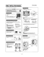
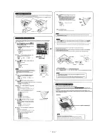
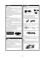
Panel installation (continued)
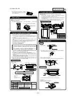
Work procedure
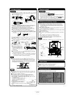
1. Make sure that the indoor unit is positioned at the correct height with the supplied level gauge.
Remove the level gauge before you install the panel.
2. Screw the two bolts of the supplied four bolts by about 5mm. (
z
mark
) [Figure 1]
3. Attach the supplied hook to the indoor unit with the screw (1 screw). [Figure 2]
4. Open the air return grille.
5. Remove the screw of a corner panel and remove a corner panel. (four places) [Figure 3]
6. Hang the panel on two bolts. (
z
mark
) [Figure 4]
7. Rotate the hook and put it into the slot of the panel. And install the panel temporarily.
[Figure 5]
8. Tighten the two bolts which were used to install the panel temporarily and the other two bolts.
9. Open a lid of the control box.
10. Fix the louver motor wiring and the drain pump wiring with clamp. And put louver motor wiring into
the control box. [Figure 6]
11. Connect the connector of louver motor. [Figure 6]
12. Attach two chains to the air return grille with two screws. [Figure 7]
13. Install the corner panels back to original places. At that time attach the chains to the panel with
screws together.
14. Close the air return grille.
Piping side
Control box
Drain hose Side
Corner panel
Screw
[Figure 7]
[Figure 4]
[Figure 3]
[Figure 5]
[Figure 5]
[Figure 2]
[Figure 1]
Chain
Chain
[Figure 6]
Drain pump connector
Louver motor connector
Wire intake
Wiring clamp
Louver motor wiring
Drain pipe
Caution
z
Install the drain pipe according to the installation manual in order to drain properly.
Imperfection in draining may cause fl ood indoors and wetting the household goods etc.
z
Do not put the drain pipe directly into the ditch where toxic gas such as sulfur, the other harmful and
infl ammable gas is generated. Toxic gas would fl ow into the room and it would cause serious
damage to user’s health and safety (some poisoning or defi ciency of oxygen). In addition, it may
cause corrosion of heat exchanger and bad smell.
z
Connect the pipe securely to avoid water leakage from the joint.
z
Insulate the pipe properly to avoid condensation drop.
z
Check if the water can fl ow out properly from both the drain outlet on the indoor unit and the end of
the drain pipe after installation.
z
Make sure to make descending slope of greater than 1/100 and do not make up-down bend and/
or trap in the midway. In addition, do not put air vent on the drain pipe. Check if water is drained
out properly from the pipe during commissioning. Also, keep suffi cient space for inspection and
maintenance.
Wiring-out position and wiring connection
z
Electrical installation work must be performed according to the installation manual by an electrical
installation service provider qualifi ed by a power provider of the country, and be executed according
to the technical standards and other regulations applicable to electrical installation in the country.
Be sure to use an exclusive circuit.
z
Use specifi ed cord, fasten the wiring to the terminal securely, and hold the cord securely in order not
to apply unexpected stress on the terminal.
z
Do not put both power source line and signal line on the same route. It may cause
miscommunication and malfunction.
z
Be sure to do D type earth work.
z
For the details of electrical wiring work, see attached instruction manual for electrical wiring work.
1. Remove a lid of the control box (2 screws).
2. Hold each wiring inside the unit and fasten them to terminal block securely.
3. Fix the wiring with clamp.
4. Install a lid of the control box back to original place.
Panel installation
z
After wiring work fi nished, install the panel on the indoor unit.
z
Refer to attached panel installation manual for details.
Indoor unit
hose
Strap (Accessory)
Pipe cover (Accessory)
The thickness of insulation should be 20mm or more.
Pipe cover (small)
(For insulation)
(Accessory)
Unit
pipe cover (big)
(For insulation)
(Accessory)
Joint for VP-20
(Prepare on site)
Drain socket
Connect
VP-20
(Prepare on site)
Pipe cover (small)
(For insulation)
(Prepare on site)
Drain hose
(Accessory)
Clamp
(Accessory
*
Descending stop greater than 1/100
As wide as possible
(about100mm)
VP-30 or bigger
Accessory items
1
Hook
1 piece
For fi xing temporarily
2
Chain
2 pieces
3
Bolt
4 pieces
For installing the panel
4
Screw
1 piece
For attaching a hook
5
Screw
2 pieces
For attaching a chain
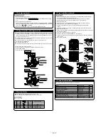
Check list after installation
z
Check the following items after all installation work completed.
Check if
Expected trouble
Check
The indoor and outdoor units are fi xed securely?
Falling, vibration, noise
Inspection for leakage is done?
Insuffi cient capacity
Insulation work is properly done?
Water leakage
Water is drained properly?
Water leakage
Supply voltage is same as mentioned in the model name plate? PCB burnt out, not working at all
There is mis-wiring or mis-connection of piping?
PCB burnt out, not working at all
Earth wiring is connected properly?
Electric shock
Cable size comply with specifi ed size?
PCB burnt out, not working at all
Any obstacle blocks airfl ow on air inlet and outlet?
Insuffi cient capacity
Drain plug
Power source side terminal block
Earth
Wiring between indoor
and outdoor unit
Signal side terminal block
Remote controller line
Wiring clamp
Single split (PAC) series
Power source side terminal block
Earth
Indoor power source line
Signal side terminal block
Signal line (shielded cord)
Remote controller line
Wiring clamp
VRF (KX) series
Earth (signal line)
(see next page)
Summary of Contents for FDE112KXE6A
Page 104: ... 102 ...
Page 111: ... 108 b Ceiling cassette 4 way Compact type FDTC Models All moddels B PJA003Z331 ...
Page 112: ... 109 c Ceiling cassette 2 way type FDTW Models FDTW28KXE6 45KXE6 56KXE6 B PJB001Z560 ...
Page 113: ... 110 Models FDTW71KXE6 90KXE6 B PJB001Z561 ...
Page 114: ... 111 Models FDTW112KXE6 140KXE6 B PJB001Z562 ...
Page 115: ... 112 d Ceiling cassette 1 way type FDTS Model FDTS45KXE6 A PJC001Z195 ...
Page 116: ... 113 Model FDTS71KXE6 A PJC001Z196 ...
Page 117: ... 114 e Ceiling cassette 1 way compact type FDTQ Models All models A PJC001Z190 ...
Page 118: ... 115 Models All models Duct panel A PJC001Z240 ...
Page 121: ... 118 Models FDU224KXE6 280KXE6 B PJD001Z230 ...
Page 123: ... 120 Models FDUM112KXE6 140KXE6 B PJR002Z259 ...
Page 124: ... 121 h Duct connected Ultra thin Low static pressure type FDQS Models All models C PJC001Z200 ...
Page 125: ... 122 i Wall mounted type FDK Models FDK22KXE6 28KXE6 36KXE6 45KXE6 56KXE6 B PHA000Z983 ...
Page 126: ... 123 Models FDK71KXE6 B PHA000Z984 ...
Page 127: ... 124 j Ceiling suspended type FDE Models FDE36KXE6A 45KXE6A 56KXE6A B PFA003Z826 ...
Page 128: ... 125 Models FDE71KXE6A 112KXE6A 140KXE6A B PFA003Z827 ...
Page 129: ... 126 k Floor standing with casing type FDFL Models All models B PGD000Z053 ...
Page 130: ... 127 l Floor standing without casing type FDFU Models All models A PGD000Z058 ...
Page 131: ... 128 m Duct Connected Compact and Flexible type FDUH Models All models A PJC001Z255 ...
Page 138: ... 135 ...
Page 139: ... 136 ...
Page 143: ... 140 b ...
Page 144: ... 141 ...
Page 191: ... 188 5 4 Installation of outdoor unit ...
Page 193: ... 190 ...
Page 194: ... 191 ...
Page 195: ... 192 ...
Page 196: ... 193 ...
Page 197: ... 194 ...
Page 198: ... 195 ...
Page 199: ... 196 ...
Page 200: ... 197 ...
Page 201: ... 198 ...
Page 202: ... 199 ...
Page 203: ... 200 ...
Page 204: ... 201 ...
Page 205: ... 202 ...
Page 206: ... 203 ...
Page 207: ... 204 ...
Page 208: ... 205 ...
Page 210: ... 207 ...
Page 211: ... 208 ...
Page 212: ... 209 ...
Page 215: ... 212 2 model type DIS model type HEAD ...
Page 216: ... 213 2 2 ...
Page 217: ... 214 2 2 2 2 2 ...

