background image

-

 193 

-

Summary of Contents for FDE112KXE6A

Page 1: ...E6A FDUM22KXE6 28KXE6 36KXE6 45KXE6 56KXE6 71KXE6 90KXE6 112KXE6 140KXE6 FDUH22KXE6 28KXE6 36KXE6 FDTC22KXE6A 28KXE6A 36KXE6A 45KXE6A 56KXE6A FDQS22KXE6 28KXE6 36KXE6 45KXE6 56KXE6 FDU71KXE6 90KXE6 112KXE6 140KXE6 224KXE6 280KXE6 FDFU28KXE6 45KXE6 56KXE6 71KXE6 FDTW28KXE6 45KXE6 56KXE6 71KXE6 90KXE6 112KXE6 140KXE6 FDK22KXE6 28KXE6 36KXE6 45KXE6 56KXE6 71KXE6 FDTQ22KXE6 28KXE6 36KXE6 FDFL28KXE6 45...

Page 2: ...A 131 5 1 Installation of indoor unit 131 a Ceiling cassette 4 way type FDT 132 b Ceiling cassette 4 way compact type FDTC 137 c Ceiling cassette 2 way type FDTW 142 d Ceiling cassette 1 way type FDTS 145 e Ceiling cassette 1 way compact type FDTQ 148 f Duct connected High static pressure type FDU 151 g Duct connected Middle static pressure type FDUM 157 h Duct connected Ultra thin Low static pres...

Page 3: ...Pull the cover downward to open it All displays are described in the liguid crystal display for explanation The figure below shows the remote control with the cover opened Installation of remote control DO NOT install it on the following places in order to avoid malfunction 1 Places exposed to direct sunlight 2 Places near heat devices 3 High humidity places 4 Hot surface or cold surface enough to...

Page 4: ...d by one tap That tap is retained for 3 minutes after changing the indoor fan tap 3 If the thermostat OFF is established during the above control the indoor fan tap at the thermostat ON is retained so far as the thermostat is turned OFF 4 After stopping the cooling operation the indoor unit continues to run at Lo for 15 seconds b When the humidity sensor is provided FDT Series only Optional 1 Oper...

Page 5: ...ost control a Control 1 When the indoor heat exchanger temperature detected with ThI R1 or R2 drops to 35 C or lower indoor fan is changed to the lower tap at each setting 2 During the hot keep operation the louver horizontal control signal is transmitted b Ending condition When the indoor fan is at the lower tap at each setting it returns to the set airflow volume as the indoor heat exchanger tem...

Page 6: ...ognize the louver position Note 1 If you press the Louver button the swing motion is displayed on the louver position LCD for 10 second The display changes to the Auto wind direction display 3 seconds later b Automatic louver level setting during heating While hot start operation and heating thermostat OFF operation the louver keeps the level position In order to prevent the cold draft whether the...

Page 7: ...ndoor PCB is ON state it enters the mode of operation check drain pump test run It is ineffective prohibited to change the switch after turning power on b When the communication with the remote controller has been established within 60 seconds after turning power on by the dip switch SW7 1 ON it enters the operation check mode Unless the remote controller communication is established it enters the...

Page 8: ...turned ON OFF based on the setting temperature of thermostat However when the thermostat OFF is likely to occur earlier because the unit is installed in a condition that warm air tends to accumulate near the ceiling the setting can be changed by using the indoor function of wired remote controller Heating room temperature compensation Since the compressor is turned ON OF at one of the setting temp...

Page 9: ... emergency stop E 63 signal is received from outdoor unit it is transmitted to the remote controller and makes stop d Fresh air processing operation input 1 If indoor unit controller receive fresh air processing operation signal 1 or fresh air processing stop signal from remote controller it output ON signal or OFF signal from CnD connector respectively 1 Operation switch ON at interlock setting a...

Page 10: ...stored in memory regardless of whether the power failure compensation setting is valid or invalid and silent mode setting is cancelled regardless of whether the power failure compensation setting is valid or invalid Running or Stopping status just before power failure If it had been operating under OFF timer mode or simple timer mode memorzed status is as stopping At the recovery of power the time...

Page 11: ...ntrol Remote controller command Remote controller command Remote controller command Intermittent operation Inverter cooling fan FMC1 2 Crankcase heater CH1 2 Magnetic contactor CM1 52X1 Magnetic contactor CM2 52X2 Solenoid valve SV1 Solenoid valve SV2 Notes 1 ON OFF ON or OFF 2 1 The EEVH1 2 of master unit are fully opened and those of slave unit are fully closed 3 2 When the unit is stopped from ...

Page 12: ...60KXE6 ii Rotation of compressor start stop order 1 The compressors will be changed over by determinating the start stop order in each heat load zone 2 In case of single use the starting order of CM1 and CM2 will be changed over on each occasion when the out door unit stops 3 In case of combination use the starting order of CM01 CM11 and CM02 CM12 will be changed over on each occation when the mas...

Page 13: ... Slave unit The compressor frequency is controlled regardless of the target frequency 1 Up to 1minutes 45 seconds after the compressor starts it is operated at 20Hz 2 When 1minutes 45 seconds has elapsed after the compressor starts it is operated at the frequency by compressor potective start control c Compressor protective start control A according to the crankcase heater ON time Master unit Slav...

Page 14: ...rol A 5 If the compressor stops within 24 minutes after startup and when the compressor starts again the compressor protective start control B is performed during the cumlative period of 24 minutes after the initial startup However when the period of 45 minutes has elapsed since compressor stopped the control is shifted to the compressor protective start control A 6 When the under dome temperature...

Page 15: ...direction of the stopping fans both FMo1 and FMo2 are reverse but its speed is less than 700min 1 for 3 seconds continuously the fan can be started During the period of 5 seconds after 52C1 is turned ON the outdoor DC fan is prohibited to start Fan tap FDC335 400 Cooling FMO1 0th speed 1st speed 2nd speed 3rd speed 4th speed 0 0 0 160 960 FMO2 0 160 400 160 960 FMO1 0 0 0 160 960 FMO2 0 160 400 16...

Page 16: ...oil are set to the initial opening degree mentioned in following table The expansion valves EEVH1 2 are operated first and after those operations are completed the expansion valve EEVSC will be operated Note 1 Expansion valves of master unit and slave unit are operated respectively 4 Fan motors FMo1 FMo2 and compressor start 15 seconds after the compressor ON conditions are satisfied Cooling Heati...

Page 17: ...2 SST 25 C Note SST Low pressure saturated temperature detected with low pressure sensor LPS f Crankcase heater CH1 is turned OFF when the under dome temperature Tho C1 40 C and CM1 is ON g Crankcase heater CH2 is turned OFF when the under dome temperature Tho C2 40 C and CM2 is ON Note f and g are the protection for thermistor Tho C1 C2 breakage Heating Cooling Cooling Heating FMo1 2 OFF OFF ON 2...

Page 18: ...ted 1 When the temperature detected with both outdoor heat exchanger temperature thermistors Tho R1 and Tho R2 is higher than 9ºC 2 Or when 12 minutes have elapsed since defrosting started Cold region setting J14 is open 1 When Tho R1 and Tho R2 9ºC is satisfied after 2 minutes and 30 seconds have elapsed since defrosting started and when either of following conditions is satisfied the defrosting ...

Page 19: ...ses to lower than 90 C it makes the compressor restarted automatcally 2 If this control mentioned in ii 1 is activates 5 times within 60 minutes it makes the compressor anomalous stop and displays E36 In case of anomalous stop it cannot be operated again until the discharge pipe temperature decreases to lower than 90 C for 60 minutes continuously b Current safe control Current safe control is done...

Page 20: ...ond step The compressor that receives cur rent safe control command first decreases the frequency and when its frequency is retaining at certain frequency such retained frequency information is transmitted to master unit Master unit will send the command to all other operating compressors in same refrigeration system to decrease frequency up to the same frequency as the first compressor reduced to...

Page 21: ...ously Maximum compressor frequency control 1 By controlling the maximum compressor frequency according to the rising outdoor air temperature it makes the in verter secondary current decreasing and protects the controller from rising temperature Compressor frequency is also controlled by detecting inverter secondary frequency 2 Initiation condition Outdoor air temperature 35ºC For cooling operation...

Page 22: ...ndoor units exceeds 80 units all corresponding units are stopped with the error of excessive number of connected indoor units ii The number of connected indoor units is checked when the automatic address setting is completed or when turning the power ON or starting operation of indoor units after completion of manual address setting iii When the error of exessive number of connected indoor units E...

Page 23: ...vided for respective categories System stop All stop including master slave units Unit stop Stop in the unit of outdoor unit Compressor stop Stop in the unit of compressor b Control contents of auto backup operation i Condition of auto backup operation is established when the dip switch SW3 2 on the PCB of master unit is turned ON selected ii However the switching of SW3 2 is effective only at the...

Page 24: ... thermistor anomaly Under dome temperature thermistor anomaly Power transitor temperture thermistor anomaly Compressor startup failure Rotor position detection failure Emergency stop Anomaly contents Anomalous stop of master outdoor unit Anomalous stop of slave outdoor unit System stop Unit stop Compressor stop System stop Unit stop Compressor stop Remote controller error display Outdoor heat exch...

Page 25: ...garding the dip switch SW3 2 for automatic backup operation it is invalid during test run operation regardless whether SW3 2 is turned ON valid or OFF invalid In order to check trouble during test run operation d Control during test run If indoor units are normal i Heating operation is performed with SW5 2 OFF while cooling operation is performed with SW5 2 ON ii Indoor EEV control at the end of t...

Page 26: ...If CnS1 terminal is used for demand control pulse input allot the 1 of P11 and open J13 and if CnS2 terminal is used for demand control level input allot the 1 of P12 and short J13 Note More than one function cannot operate at same time 1 Setting means Master Set only the master unit No necessary to set the slave unit Master Slave Set both master slave unit same External input terminal External in...

Page 27: ... it is transferred to optional centralized controller J13 Shorted J13 Open 5 CnS1 performs the following operation according to switching the jumper wire J13 shorted or open In case of pulse input the pulse width is 500ms or larger PUSH CnS1 input OFF Open Remote controller operation Remote controller display Air conditioner operation stop PUSH PUSH PUSH OFF Center Remote ON Shorted Center OFF OFF...

Page 28: ...2 OFF 735 26 12 14 50Hz 4 74Hz 2 50Hz 2 OFF 800 28 14 14 54Hz 4 78Hz 2 50Hz 2 OFF 850 30 14 16 58Hz 4 42Hz 4 58Hz 2 OFF 900 32 16 16 60Hz 4 46Hz 4 62Hz 2 OFF 80 60 40 0 SW 4 6 Upper limit operation Hz of compressor Compressor output SW 4 5 0 1 0 1 0 0 1 1 960 34 16 18 66Hz 4 50Hz 4 66Hz 2 OFF 1010 36 18 18 70Hz 4 52Hz 4 70Hz 2 OFF 80 60 40 0 SW 4 6 Upper limit operation Hz of compressor Compressor...

Page 29: ...ration If the signal is input to the slave unit it is invalid d When the Silent mode start signal from indoor unit and the Silent mode signal from outdoor unit are received it enters the silent mode operation under or condition e When silent mode signals from all indoor units become Silent mode end and when silent mode signal input to CnG2 on outdoor unit becomes open the silent mode operation is ...

Page 30: ... fans are operated at the maximum speed 4th speed once every 10 minutes ii The outdoor fan runs for 30 minutes iii During this snow protection control the magnetic contactor 52C1 of the compressor is ON 4 Forced cooling heating operation Master unit Note Following explanation is based on using CnG1 terminal and setting function P13 2 with 7 segment display However other terminals can be used with ...

Page 31: ...remote controller 52XE is not turned OFF but it will be turned OFF autmatically after the error is recovered subsequently Remote controller reset case d If at least one of connected indoor units is operating the operation output relay 52XR is turned ON Operation means the state that remote controller is turned ON in which the fan opertion and the thermostat OFF is included but the error stop is ex...

Page 32: ...Turn SW5 3 pump down switch ON 4 Turn SW5 1 test run switch ON d End condition If any of the following conditions is satisfied this control ends i If the low pressure LP 0 01MPa is detected for 5 seconds continuously this control ends normally and indicates followings Red LED Keeps lighting Green LED Keeps flashing 7 segment display PdE Remote controller Stop ii Anomalous all stop by the error det...

Page 33: ...yed it jumps to the code No C10 9 The data of code No C54 and C55 can be erased independently The compressor cumulative operation time corresponding to the code No selected can be erased reset For resetting of the compressor cumulative operation time after replacement of compressor The resetting method is to select the code C54 or C55 first the compressor cumulative operation time corresponding to...

Page 34: ...oS Pump down opertion OPE Outdoor unit setting 2 If the state of 1 is reset it is automatically switched to CXX Automatic data display mode 3 When pressing SW8 or SW9 under the state of 1 it switched to CXX However the button input is not done for 10 seconds after switching to CXX the display is changed to the spe cial display according to the priority of the state 1 When Special display occurs Wh...

Page 35: ...r temp 2 Exit Rear Tho R3 Heat exchanger temp 3 Entrance Front Tho R4 Heat exchanger temp 4 Entrance Rear Tho D1 Discharge pipe temp CM1 Tho D2 Discharge pipe temp CM2 Tho C1 Under dome temp CM1 Tho C2 Under dome temp CM2 Tho P1 Power transistor temp CM1 Tho P2 Power transistor temp CM2 Tho SC Sub cooling coil temp 1 Tho SC Sub cooling coil temp 2 Tho S Suction pipe temp Cooling operation super co...

Page 36: ...ssure sensor Order of 1 Defective high pressure sensor 0 Normal 1 Abnormal Order of 100 Anomaly in inverter 1 Order of 10 Anomaly in inverter 2 Order of 1 Anomalous high pressure 0 Normal 1 Abnormal Order of 100 Anomalous low pressure Order of 10 Anomalous discharge pipe thermistor 1 Order of 1 Anomalous discharge pipe thermistor 2 0 Normal 1 Abnormal Order of 100 Defect CM1 starting Order of 10 D...

Page 37: ...rol status Operation priority switching High pressure control of cooling low pressure control of cooling Heating high pressure compensation Low pressure of heating Snow protection fan control Data reset Refrigerant quantity check status Counter Liquid back error Counter Thermistor disconnection Counter Inverter 1 communications error Counter High pressure protection Counter Compressor 1 starting f...

Page 38: ...address setting Input stating indoor address Input the number of connected indoor units Polarity difinition Counter Outdoor inverter communications error 2 Counter Anomalous low pressure Immediately after starting Counter Anomalous low pressure Under operation New superlink setting Example 2 11 0 Current superlink 1 New superlink 0 Automatic address setting standby 1 Automatic address setting star...

Page 39: ...Minimum units AUX AUE A01 A02 A03 A04 Auto address setting on Indoor unit address No assignment normal ending Indoor unit address No assignment error 1 Indoor unit address No assignment error 2 Indoor unit address No assignment error 3 Super Link setting error ...

Page 40: ... are always saved in the memory and if the trouble occurs the data writing is stopped and the operation data prior to the trouble occurrence are recorded These data can be retrieved to personal computer through RS232C connector on the outdoor control PCB and utilized for probing the cause i Opearation data for a period of 30 minites prior to the present operation are saved and updated sequentially...

Page 41: ...535 0 255 A D value A D value A D value A D value A D value A D value A D value A D value A D value A D value 10 min 1 10 min 1 1pulse 1pulse 1pulse 1 unit 1 unit 1Hz 1Hz 1Hz 1 1 2 2 1 1 1 1 1 1 1 1 1 2 2 2 2 2 1 2 1 2 2 2 1 Tho P2 Power transistor temp Heat dissipation fin Tho SC Sub cooling coil temp 1 Tho H Sub cooling coil temp 2 Tho S Suction pipe temp Cooling operation super cooling Super he...

Page 42: ... 3 Time conditions CM1 3 minute delay timer CM2 3 minute delay timer Bit0 Defective outdoor temperature thermistor Bit1 Defective outdoor unit heat exchanger 1 thermistor Bit2 Defective outdoor unit heat exchanger 2 thermistor Bit3 Defective outdoor unit heat exchanger 3 thermistor Bit4 Defective outdoor unit heat exchanger 4 thermistor Bit5 Defective discharge pipe thermistor 1 Bit6 Defective dis...

Page 43: ...ol status Td Control status Control status Control status HP Control status Control status CS Control status LP Control status Control status Control status Control status PT Check operation and Refrigerant quantity check Control status Control status CH compressor protective start Switch etc Control status Control status Control status Control status 0 None 1 Defrosting status 1 2 Defrosting stat...

Page 44: ... 1 1 1 1 1 1 1 1 2 1 1 2 2 1 1 2 1 1 2 Control status Control status Control status Control status Control status Control status Control status Control status Control status Control status INV1 information INV2 information Registered indoor units 1 8 required Hz Registered indoor units 1 8 answer Hz Operation priority switching High pressure control of cooling Cooling low pressure compensation Low...

Page 45: ... slave CM2 Equal oil rotation Hz Equal oil rotation status Compressor of incomplete differential pressure start Under dome overheat degree CM1 Under dome overheat degree CM2 SHTc frequency restriction Indoor unit EEV control Compressor stop causes Anomalously stopped compressor Backup display Backup cumulative time Control status 32768 32767 32768 32767 Bit5 LP error compensation Bit4 External reg...

Page 46: ...n SW Normal Test run Test run Heating Cooling Pump down SW Normal Pump down SL selector New SL Auto Old SL Capacity measurement mode Capacity measurement mode Capacity measurement mode Data erase write 7 segment display code No increasing order of 1 7 segment display code No increasing order of 10 Model selection Demand ratio selection Master slave unit setting address Master slave unit setting ad...

Page 47: ...s the failure related to any hardware parts SV main body coil capillary check valve sensor etc Is it a major component Compressor inverter PCB and outdoor DC fan motor Is it a failure of electrical component Error on indoor unit or outdoor unit Indoor unit Outdoor unit Is the remote controller connected Was the power supply reset after the error occurred Check and write down the momentary data ret...

Page 48: ...ait for 3 minutes after turning the power circuit breaker off Disconnect the fan motor wires Both the power cable and control wires Turn the power circuit breaker OFF Wait 3 minutes Check whether DC15V between of CNI1 on the control PCB is detected Check E41 42 45 48 Connect the wires of fan motor 1 or 2 Power ON Test run switch ON If DC15V is detected primary check is completed Return to and chec...

Page 49: ...stem error 81 E37 E37 1 2 E37 4 5 E37 5 6 Outdoor heat exchanger temperature thermistor Tho R and subcooling coil temperature thermistor Tho SC H anomaly Thermistor wire breakage 82 E38 E38 Outdoor air temperature thermistor anomaly Tho A Thermistor wire breakage 83 E39 E39 1 2 Discharge pipe temperature thermistor anomaly Tho D1 D2 Thermistor wire breakage 84 E40 E40 High pressure anomaly 63H1 1 ...

Page 50: ...g or heating operation from remote controller Note 1 Outdoor 35ºC Indoor 27ºCDB 19ºCWB It is normal This unit is designed to start in the soft start mode by detecting the compressor under dome temperature when it restart after power reset It is necessary to replace to higher capacity unit or to install additional unit Compressor refrigerant oil protective control at starting is activated For the c...

Page 51: ...ration from remote controller Note 1 Outdoor 7ºC Indoor 20ºCDB It is normal This unit is designed to start in the soft start mode by detecting the compressor under dome temperature when it restart after power reset It is necessary to replace to higher capacity unit or to install additional unit Compressor refrigerant oil protective control at starting is activated For the contents of control refer...

Page 52: ... resistance may drop to a few MΩ because of refrigerant migrated in the compressor When the earth leakage breaker is activated at lower insulation resistance check the following points 6 hours after power ON check if the insulation resistance recovers to normal When power ON crankcase heater heat up compressor and evaporates the refrigerant migrated in the compressor Check if the earth leakage bre...

Page 53: ...eness Prevent the vibration from transmitting to wall and etc by fixing pipes on the wall tightly or wrapping rubber cushion around the pipe which goes through the hole in the wall or applying other appropriate means Strength of ceiling wall floor etc may be insufficient Review the installation place or apply reinforcement to increase the strength Check for leaning of installed unit or incorrect m...

Page 54: ...s through inside of piping of air conditioner It is likely to occur particularly during cooling or defrosting in the heating mode It is normal The noise vibration occurs when the refrigerant starts or stops flowing It is normal When the defrosting starts or stops during heating mode the refrigerant flow is reversed due to switching 4 way valve This causes a large change in pressure wich produces a...

Page 55: ...ion of air nitrogen etc In such case it is necessary to recover refrigerant vacuum dry and recharge refrigerant Since there could be many causes of noise vibration the above may not cover all In such case check the conditions when where how the noise vibration occurs according to following check points and ask our consultation Indoor outdoor unit Cooling heating fan mode Startup stop during operat...

Page 56: ...g YES NO Does the louver link press LS till crick sound can be heard NO NO YES NO NO YES In cases of FDTW FDTS and FDTQ Does the louver operate when power on Note 1 LM Louver motor 2 LS Limit switch YES NO NO NO NO YES YES Operate after waiting for more than 1 minute It is normal if LM can be stopped by pressing LS two times In cases of FDT FDTC FDE and FDK Check the remote controller whether it i...

Page 57: ... between of CNW0 OK Is DC5V detected between of CNW2 Is power supply to FM LM and etc OK Note 1 FDT and FDTC series F200 F201 Other than FDT and FDTC Fuse between wires 1 2 3 4 Other than FDT and FDTC series FDT and FDTC series Is DC18V or higher detected between Red Red CNW2 at the transformer secondary side Outdoor Noise filter PCB anomaly Replace it Wrong wiring or broken wires between outdoor ...

Page 58: ...dary side Is DC18V detected between of CNW2 Disconnect the remote controller wires NO Is DC15V or higher detected between X Y of indoor unit terminal block Other than FDT and FDTC Series FDT and FDTC Series YES YES YES YES NO NO YES NO NO Correct it Replace wires Replace remote controller Indoor power PCB anomaly Replace it Indoor control PCB anomaly Replace it Replace transformer Indoor control P...

Page 59: ...ise filter PCB Connect wires correctly Indoor control PCB anomaly Replace it Indoor outdoor control PCB anomaly Replace it Remote controller anomaly Replace it Breakage of wires for remote controller Replace it Correct the connecting wires between indoor and outdoor units Outdoor control PCB anomaly Replace it Breakage of connecting wire Noise Indoor control PCB anomaly Replace it 2 Error detectio...

Page 60: ... t there any short circuit between phases of noise filter Isn t there any crack or damage on power transistor module or diode stack Isn t there any anomaly on reactor Replace noise filter Replace reactor Replace inverter PCB Replace fuse 2 Error detection method 3 Condition of error displayed 4 Presumable cause Fuse blown Noise filter anomaly Anomalous connection of wire between PCBs Indoor contro...

Page 61: ...Is The fuse on indoor control PCB OK Is AC18V or higher is detected between Red Red at secondary side of indoor transformer 1 Is DC10 11V between X Y at indoor control PCB side when removing remote controller Note 1 except FDT and FDTC Fuse blown Replace fuse Transformer anomaly Remote controller wire short circuited Remote controller anomaly Indoor control PCB anomaly Remote controller anomaly Br...

Page 62: ...between L1 L2 L2 L3 L3 L1 respectively at outdoor terminal block Is AC220 240V detected between L N at indoor teminal block NO NO NO NO NO YES YES YES YES YES YES A WAIT Refer next page Indoor control PCB anomaly Replace it Indoor control PCB anomaly Replace it Remote controller anomaly Replace it Breakage of wires for remote controller Replace it Correct the connecting wires between indoor and ou...

Page 63: ...there any anomaly on outdoor fan motor Once turn OFF the breaker and turn ON it again at 3 minute after power OFF Does it become normal Check inverter before replacement of 52C NO NO NO NO NO NO YES YES YES YES YES YES A B Normal Malfunction by temporary noise Refer next page Replace noise filter Connect the connecting wire properly Correct connection In case of breakage of wire replace it Outdoor...

Page 64: ... Replace electrolytic capacitor Replace reactor Isn t there any short circuit between phases at input terminal of inverter PCB Isn t there any crack or damage on power transistor module or diode stack Isn t there any anomaly on reactor Isn t there any anomaly on electrolytic capacitor NO NO NO NO NO B YES YES YES YES YES 2 Error detection method 3 Condition of error displayed 4 Presumable cause Fu...

Page 65: ...t remote controller terminal Is DC10V or higher between X Y wires detected when removing remote controller Are connecting wires between indoor and outdoor units connected properly Remote controller anomaly Remote controller anomaly Correct connecting wire Indoor control PCB anomaly 2 Error detection method 3 Condition of error displayed 4 Presumable cause Fuse blown Noise filter anomaly Anomalous ...

Page 66: ...the remote controller displays Internal check ON even after 3 minutes Reset power supply 2 1 NO Malfunction by temporary noise Check peripheral environment Indoor control PCB anomaly Replace it Remote controller anomaly Replace it 2 Error detection method When normal communication between remote controller and indoor unit is interrupted for more than 2 minutes Detectable only with the remote contr...

Page 67: ...ly is reset addresses will not be confirmed YES NO YES NO YES NO Review number of connected units Correct indoor unit address setting Implement test run Replace indoor control PCB Before replacement confirm whether the rotary switch for address setting is not damaged It was experienced that No 5 on rotary switch was not recognized 2 Error detection method More than 129 indoor units are connected i...

Page 68: ... E5 In both cases check signal line wired locally YES Is the outdoor unit address set on the indoor unit OK YES Is the LED on indoor control PCB OK YES Is protective fuse for the super link circuit blown NO Does E3 E5 occurs YES NO NO NO YES YES NO NO Temporary malfunction by noise Identify the source of noise and correct it Change to spare circuit Indoor control PCB anomaly Replace it Correct it ...

Page 69: ...ge of signal wires between indoor and outdoor units YES NO YES NO YES NO In case that indoor red LED flashes 2 times Repair signal wires Repair signal wires Go to the diagnosis of WAIT 1 Unit is normal Malfunction by temporary noise etc Outdoor control PCB anomaly Network communicaion circuit anomaly Replace it Unit is normal Malfunction by temporary noise etc 2 Error detection method When the com...

Page 70: ...ance characreristics of indoor heat exchanger temperature thermistor Thi R1 R2 R3 5kΩ at 25ºC Temperature ºC Insert the connector securely Replace thermistor Thi R Replace indoor control PCB 2 Error detection method Detection of anomalously low temperature resistance of Thi R1 R2 R3 3 Condition of error displayed If 50ºC or lower is detected for 5 seconds continuously compressor stops After 3 minu...

Page 71: ...mes to prove any poor connection 15 10 5 0 10 30 40 20 50 Temperature sensor resistance k Ω Temperature C 5kΩ at 25 C Insert the connector securely Replace thermistor Thi A Replace indoor control PCB 2 Error detection method Detection of anomalously low temperature resistance of Thi A 3 Condition of error displayed If 50 C or lower is detected for 5 seconds continuously compressor stops After 3 mi...

Page 72: ...n pipe slop OK NO YES NO YES NO NO YES Check float switch Check the connection of CNI If it is loose connect it securely Replace indoor control PCB Check optional equipment Correct setting to Humidifier drain motor interlock Indoor control PCB anomaly Replace it Check the wiring of drain motor Correct it Check drain motor 2 Error detection method Float switch is activated 3 Condition of error disp...

Page 73: ... model 5 Troubleshooting All models Diagnosis Countermeasure Aren t more than 17 indoor units connected to one remote controller NO YES Remote controller anomaly Replace it Reduce to 16 or less units 2 Error detection method When it detects more than 17 of indoor units connected to one remote contorller 3 Condition of error displayed Same as above 4 Presumable cause Excessive number of indoor unit...

Page 74: ...splayed Same as above 4 Presumable cause Mistake in address setting for indoor unit Note Address setting method list Figures in are for Previous superlink models Models for new superlink protocol Models for Previous superlink protocol Indoor unit address setting Outdoor unit address setting Indoor unit address setting Outdoor unit address setting Indoor unit No SW Outdoor unit No SW Outdoor unit N...

Page 75: ...r Replace the fan motor Check power supply voltage Replace fan motor and power PCB Replace fan motor If the anomaly persists after replacing the fan motor replace the indoor control PCB Malfunction by temporary noise 2 Error detection method Detected by revolution speed of indoor fan motor 3 Condition of error displayed When actual revolution speed of indoor fan motor drops to lower than 200min 1 ...

Page 76: ...ter Replace fan motor Replace fan motor and power PCB Replace fan motor If this anomaly persists after replacing the fan motor replace indoor control PCB Malfunction by temporary noise 2 Error detection method Detected by revolution speed of indoor fan motor 3 Condition of error displayed When actual revolution speed of indoor fan motor drops to lower than 200min 1 for 30 seconds continuously the ...

Page 77: ...ayed Same as above 4 Presumable cause Mistake in SW7 1 setting Due to forgetting to turn OFF SW7 1 after indoor operation check Note Indoor operation ckeck drain pump check mode If the power is ON after SW7 1ON indoor operation check drain pump check mode can be established 1 When the communication between remote controller and indoor PCB is established 15 seconds after power ON it goes to indoor ...

Page 78: ...s again within 60 minutes after the initial detection 4 Presumable cause Anomalous connection of remote controller temperature thermistor Remote controller temperature thermistor anomaly Remote controller PCB anomaly Note After 10 seconds has elapsed since remote controller temperature thermistor was switched from invalid to valid E28 will not be displayed even if the thermistor harness is disconn...

Page 79: ...or and outdoor units correctly YES NO Is the voltage between L1 N at the terminal block on indoor unit AC220 240V NO Is the voltage between L1 L2 L2 L3 and L3 L1 at the terminal block on outdoor unit AC380 415V respectively YES YES NO Correct the wiring Replace outdoor control PCB Disconnection or breakage of wire between indoor and outdoor unit Replace indoor unit PCB 2 Error detection method 3 C...

Page 80: ...ss setting is not damaged It was experienced that No 5 on rotary switch was not recognized 2 Error detection method When the microcomputer of outdoor control PCB recognizes the dupplicated address No by scanning all adresses of outdoor units in the same superlink system 3 Condition of error displayed When duplicated outdoor unit address No exists in the same superlink system 4 Presumable cause Mis...

Page 81: ...it occurs immediately after the power on or during operation or stopping It will be useful to persuade the customer why an improvement of power supply is required by showing these data Propose an improvement to the customer Check it as much as possible under the operating conditions for 30 minutes before error occurred Replace outdoor control PCB Wait and see without taking any action 2 Error dete...

Page 82: ...the refrigerant amount is insufficient or not Check the gas leakage Insert connector securely Check if the characteristics are correct by referring the characteristics chart of E39 And if necessary replace the discharge pipe temperature thermistor Check it as much as possible under the operating conditions for 30 minutes before error occurred Wait and see Continue to obtain data if possible Keep c...

Page 83: ... fan rotates Save data for 30 minutes before stopping in Mente PC NO NO NO NO NO NO NO YES YES YES YES YES YES YES Is the characteristics of Tho C1 2 OK Check and save the data of operating condition Check the ROM version Comfirmation of SV1 2 operation Correct the connection of refrigerant piping and or signal wiring properly Adjust refrigerant amount properly Replace SV1 2 Replace the coil of SV...

Page 84: ...opping Check the sensed value Compare the temperature on Mente PC with actual measured value Insert the connector securely Replace Thermistor Tho SC Tho H Tho R Replace outdoor control PCB 2 Error detection method Detection of anomalously low temperature resistance of Tho R or Tho SC or Tho H 3 Condition of error displayed If 50 C or lower is detected for 5 seconds continuously within 2 minutes to...

Page 85: ...s immediately after the power on or during operation or stopping Check the sensed value Compare the temperature on Mente PC with actual measured value Insert the connector securely Replace thermistor Tho A Replace outdoor control PCB 2 Error detection method Detection of anomalously low temperature resistance of Tho A 3 Condition of error displayed If 30 C or lower is detected for 5 seconds contin...

Page 86: ...ether it occurs immediately after the power on or during operation or stopping Check the sensed value Compare the temperature on Mente PC with actual measured value Insert the connector securely Replace thermistor Tho D1 or D2 Replace outdoor control PCB 2 Error detection method Detection of anomalously low temperature resistance of Tho D1 D2 3 Condition of error displayed If 3 C or lower is detec...

Page 87: ...h pressure sensor itself according to the troubleshooting procedure of E54 after retarting operation If the high pressure sensor PSH fails replace it If the connector is disconnected or the harness is broken correct it Also check whether the high pressure switch is properly mounted or not Open operation valve Check it as much as possible under the operating conditions for 30 minutes before error o...

Page 88: ...e Mente PC If the cooling fan does not run in spite of the operation ON range check the voltage at the connector of cooling fan If the 220 240V is detected repalce cooling fan motor If 0V is detected replace outdoor control PCB After checking the loose connection of connetor or breakage of harness replace inverter PCB Connect the connector of thermistor securely Or replace power transistor tempera...

Page 89: ...tariner of oil separator If necessary replace the capillary tube and strainer as well Repair it according to the troubleshooting of E48 Replace inverter PCB or outdoor fan motor Check it as much as possible under the operating conditions for 30 minutes before error occurred Wait and see Continue to obain data if possible Keep connecting the Mente PC Replace compressor that is failed to startup Rep...

Page 90: ...ed indoor units exceeds the limitation if tentative operation is required turn ON the dip switch SW5 4 on the outdoor control PCB However since this tentative solution could cause trouble be sure to correct it as soon as possible Signal wire may be connected to other outdoor unit system Correct the signal wire Correct addresses Either one of addresses is wrong If the address corrected with rotary ...

Page 91: ... 1 SW1 2 SW1 3 SW1 4 JSW2 1 JSW2 2 JSW2 3 JSW2 4 OFF OFF OFF OFF OFF OFF 1 OFF Check and save the data of operating conditions Replace inverter PCB or outdoor fan motor Check it as much as possible under the operating conditions for 30 minutes before error occurred Wait and see Continue to obain data if possible Keep connecting the Mente PC Check whether the harness is broken Check whether the con...

Page 92: ...ecause it is judged that the power rest is not done after changing address Correct signal line In case of automatic address setting signal line cannot be connected to other outdoor unit system Test run Replace outdoor control PCB Rotary switch anomaly Before replacement please confirm whether the rotary switch for address setting is not damaged It was experienced that No 5 on rotary switch was not...

Page 93: ...and save the data of operating conditions Replace fan motor Replace inverter PCB or fan motor Check it as much as possible under the operating conditions for 30 minutes before error occurred Wait and see Continue to obain data if possible Keep connecting the Mente PC Replace fan motor Replace outdoor control PCB 2 Error detection method If 400 min 1 or lower of the fan rotation command and the sta...

Page 94: ...e according to the piping length instructed on the label pasted on the panel of the unit Check whether the service valves are open Correct the connection of low pressure sensor connector Replace low pressure sensor Replace outdoor control PCB Correct the connection of temperature thermistor connector of heat exchanger Replace temperature thermistor of heat exchanger at evaporator side Replace cont...

Page 95: ...conds after compressor ON compressor stops When the compressor is restarted automatically after 3 minutes delay if this anomaly occurs 3 times within 40 minutes 4 Presumable cause Broken thermistor harness or the internal wire of sensing section Check the molded section as well Disconnection of thermistor harness connection connector Outdoor control PCB anomaly Note 1 E55 1 Tho C1 E55 2 Tho C2 2 E...

Page 96: ...ure by pressure gauge YES Output voltage V Output voltage V Check and save the data of operating conditions Check the conditions whether it occurs immediately after the power on or during operation or stopping Check the sensed value Insert the connector securely and restart operation Temporary malfunction by noise Correct if the source of noise is specified Replace sensor PSH PSL Replace outdoor c...

Page 97: ... Check the conditions whether it occurs immediately after the power on or during operation or stopping Check the sensed value Compare the temperature of Mente PC data with actual measured value Insert the connector securely Replace power transistor temperature thermistor Tho P1 P2 Replace outdoor control PCB 2 Error detection method Detection of anomalously low temperature resistance of Tho P1 P2 ...

Page 98: ...e data of operating condition Refrigerant might be migrated in the refrigerant oil in the compressor Wait for about one hour under the condition of power ON and start again Turn the on crankcase heater ON and evaporate the liquid refrigerant migrated in the compressor The model setting could be wrong Check the dip switch for model setting on the outdoor control PCB 2 Error detection method E58 is ...

Page 99: ...of software Is it latest Check whether the solenoid valve SV6 at the exit of oil separator is open during compressor stopping Is the pressure equalized Replace the cable If there is a problem on the terminal of compressor replace the compressor Wait and see Replace compressor Replace inverter PCB or power transistor module Check 15V on the outdoor control PCB and check power transistor with invert...

Page 100: ...eck it as much as possible under the operating conditions for 30 minutes before error occurred Correct it according to the troubleshooting procedure of E59 Correct it according to the troubleshooting procedure of E42 Replace compressor Check the insulation resistance and coil resistance of compressor If necessary replace compressor Replace inverter PCB Replace compressor Replace inverter PCB Tempo...

Page 101: ...ure Is E61 occur Reset the power supply and restart operation NO NO YES YES Is the address setting of master and slave outdoor units OK Corrent Replace the outdor unit PCB Anomalous noise etc 2 Error detection method When the communication between master unit and slave units is not established 3 Condition of error displayed Same as above 4 Presumable cause Signal wire anomaly Outdoor control PCB a...

Page 102: ...in Mente PC YES NO NO YES Check and save the data of operating conditions Check the conditions whether it occurs immediately after the power on or during operation Replace remote control PCB Replace indoor control PCB Check the cause of emergency stop It is better to have the data for 30 minutes before stopping when instructing the installer 2 Error detection method When ON signal is inputted to t...

Page 103: ...recaution is the important contents for safety be sure to observe them WARNING and CAUTION are described as follows Indicates an imminently hazardous situation which will result in death or serious injury if proper safety procedures and instructions are not adhered to Indicates a potentially hazardous situation which may result in minor or moderate injury if proper safety procedures and instructio...

Page 104: ... 102 ...

Page 105: ... A B and C in Figure 1 Take care not to drop screws on the PCB etc when removing them Make sure to collect when dropped any 4 Open the front part of the control box as shown in Figure 2 Don t open the front part more than 90º Avoid exerting undue force on the open front part Provide a support under the open fuont part 5 After opening the front part of the control box you can access to the inverter...

Page 106: ... 104 Table 1 Switch Setting Model JSW10 JSW11 1 2 3 4 All models INV1 OFF ON OFF OFF INV2 OFF ON OFF ON ...

Page 107: ... OFF ON OFF FDC450 ON OFF ON OFF FDC504 OFF ON ON OFF FDC560 ON ON ON OFF FDC615 OFF OFF OFF ON FDC680 ON OFF OFF ON SW4 Change demand ratio ON OFF Function SW4 5 ON SW4 6 OFF Compressor capacity 60 ON Compressor capacity 0 OFF OFF Compressor capacity 80 ON Compressor capacity 40 SW4 Master Slave setting ON OFF Function SW4 7 Master OFF ON Slave ON OFF Function SW5 1 ON Test run switch test run OF...

Page 108: ...nal input Defrost end temperature KXR KX Normal Cold region Defrost start temperature Outdoor unit type selection As per voltage Level See table 3 Erase Keep OFF Keep OFF New SL Previous SL Normal Heating Normal New SL Auto Normal Test run Heating Cooling Normal Pump down Erase Write Keep OFF Keep OFF Keep OFF Keep OFF Keep OFF Keep OFF Keep OFF Keep OFF Keep OFF Keep OFF Reserved Model selection ...

Page 109: ...NU2 Under dome thermistor 1 CM2 Tho P1 CNP1 Power transistor thermistor 1 CM1 Tho P2 CNP2 Power transistor thermistor 2 CM2 Tho S CNTH Suction pipe thermistor Tho SC CNF1 Sub cooling coil thermister 1 Tho H CNF2 Sub cooling coil thermister 2 CT1 Current sensor CM1 CT2 Current sensor CM2 PSH CNL1 High pressure sensor PSL CNL2 Low pressure sensor 63H1 1 CHQ1 High pressure switch CM1 63H1 2 CHQ2 High...

Page 110: ... 107 C PJF000Z053 3 ELECTRICAL WIRING 3 1 Indoor unit a Ceiling cassette 4 way type FDT Models All models ...

Page 111: ... 108 b Ceiling cassette 4 way Compact type FDTC Models All moddels B PJA003Z331 ...

Page 112: ... 109 c Ceiling cassette 2 way type FDTW Models FDTW28KXE6 45KXE6 56KXE6 B PJB001Z560 ...

Page 113: ... 110 Models FDTW71KXE6 90KXE6 B PJB001Z561 ...

Page 114: ... 111 Models FDTW112KXE6 140KXE6 B PJB001Z562 ...

Page 115: ... 112 d Ceiling cassette 1 way type FDTS Model FDTS45KXE6 A PJC001Z195 ...

Page 116: ... 113 Model FDTS71KXE6 A PJC001Z196 ...

Page 117: ... 114 e Ceiling cassette 1 way compact type FDTQ Models All models A PJC001Z190 ...

Page 118: ... 115 Models All models Duct panel A PJC001Z240 ...

Page 119: ... at signal line between indoor unit 2 and outdoor unit and signal line between indoor units 3 Use twin core cable 0 3mm2 at remote controller line See spec sheet of remote controller in case that the total length is more than 100m 4 Do not put signal line and remote controller line alongside power source line 5 or 6 wires A PJD011G034 ...

Page 120: ... 117 f Duct connected High static pressure type FDU Models 90KXE6 112KXE6 140KXE6 B PJD001Z229 ...

Page 121: ... 118 Models FDU224KXE6 280KXE6 B PJD001Z230 ...

Page 122: ... 119 g Duct connected Middle static pressure type FDUM Models FDUM22KXE6 28KXE6 36KXE6 45KXE6 56KXE6 71KXE6 90KXE6 B PJR002Z258 ...

Page 123: ... 120 Models FDUM112KXE6 140KXE6 B PJR002Z259 ...

Page 124: ... 121 h Duct connected Ultra thin Low static pressure type FDQS Models All models C PJC001Z200 ...

Page 125: ... 122 i Wall mounted type FDK Models FDK22KXE6 28KXE6 36KXE6 45KXE6 56KXE6 B PHA000Z983 ...

Page 126: ... 123 Models FDK71KXE6 B PHA000Z984 ...

Page 127: ... 124 j Ceiling suspended type FDE Models FDE36KXE6A 45KXE6A 56KXE6A B PFA003Z826 ...

Page 128: ... 125 Models FDE71KXE6A 112KXE6A 140KXE6A B PFA003Z827 ...

Page 129: ... 126 k Floor standing with casing type FDFL Models All models B PGD000Z053 ...

Page 130: ... 127 l Floor standing without casing type FDFU Models All models A PGD000Z058 ...

Page 131: ... 128 m Duct Connected Compact and Flexible type FDUH Models All models A PJC001Z255 ...

Page 132: ... 129 3 2 Outdoor unit Models FDC335KXE6 K 400KXE6 450KXE6 504KXE6 560KXE6 560KXE6 K 615KXE6 680KXE6 PCB003Z060 ...

Page 133: ... ThI R1 R2 Heating operation Indoor fan control Cooling operation Frost prevention control Super heat control ThI R3 For super heat control of cooling operation Tho D For control of discharge pipe temperature Tho C For control of temperarure under the dome Tho S For control of suction pipe temperature Tho R1 R2 For control of defrosting Tho A For control of defrosting Tho R3 R4 Electronic expansio...

Page 134: ...y cause water leakage electric shock or fire Consult the dealer or a specialist about removal of the air conditioner Improper installation may cause water leakage electric shock or fire Turn off the power source during servicing or inspection work If the power is supplied during servicing or inspection work it could cause electric shock and injury by the operating fan Do not run the unit when the ...

Page 135: ...tion position 1 way is not available If it is necessary to change the number of air supply port prepare the covering materials sold as accessory Instruct the user not to use low fan speed when 2way or 3way air supply is used Do not use 2way air supply port under high temperature and humidity environment Otherwise it could cause condensation and leakage of water It is possible to set the airflow di...

Page 136: ...generated Toxic gas would flow into the room and it would cause serious damage to user s health and safety some poisoning or deficiency of oxygen In addition it may cause corrosion of heat exchanger and bad smell Connect the pipe securely to avoid water leakage from the joint Insulate the pipe properly to avoid condensation drop Check if the water can flow out properly from both the drain outlet o...

Page 137: ...ew condensation and water leakage Attention for removing drain pan The fixing components have been attached the with drain pan Pay attention to these components during installation and removing Take off the hanging hook after removing four screws During the installation of drain pan fix the drain pan firmly by using four screws after hanging it up with the fixing hook Drain pan Fixing piece Remove...

Page 138: ... 135 ...

Page 139: ... 136 ...

Page 140: ... installed nearby keep them away for more than 4m Space for installation and service z When it is not possible to keep enough space between indoor unit and wall or between indoor units close the air supply port where it is not possible to keep space and confirm there is no short circuit of airflow z Install the indoor unit at a height of more than 2 5m above the floor Indoor unit Indoor unit Wall ...

Page 141: ...ting the drain pipe z Do not set up air vent Supporting metal No bump No trap Not touching the water Trapped air will generate noises Air vent Insulation material 1 5m 2m Descending slope greater than 1 100 z When sharing a drain pipe for more than one unit lay the main pipe 100mm below the drain outlet of the unit In addition select VP 30 or bigger size for main drain pipe 4 Insulate the drain pi...

Page 142: ...ng connection z Electrical installation work must be performed according to the installation manual by an electrical installation service provider qualified by a power provider of the country and be executed according to the technical standards and other regulations applicable to electrical installation in the country Be sure to use an exclusive circuit z Use specified cord fasten the wiring to th...

Page 143: ... 140 b ...

Page 144: ... 141 ...

Page 145: ...ched still the unit height can be adjusted finely Refer to the installation manual for decorative panel for details Indoor unit Hose Center of box Drain hose piece Accessory Installed on site panel Control 97 446 90 97 640 40 Suspension bolts pitch Ceiling hole size Suspension bolts pitch Ceiling hole size Hanger plate for E F 5 Ø4 Holes for tapping screws Hole suspension bolt 95 64 278 264 310 D ...

Page 146: ...fix and wrap it with tapes to wrap and make joint part gapless Drain up The position for drain pipe outlet can be raised up to 750mm above the ceiling Use elbows for installation to avoid obstacles inside ceiling If the horizontal drain pipe is too long before vertical pipe the backflow of water will increase when the unit is stopped and it may cause overflow of water from the drain pan on the ind...

Page 147: ...move General hard type PV pipe VP 20 Transparent soft tube option Connector for drain motor CNR blue 2P Remove Insulation Attach the panel on the indoor unit after electrical wiring work Work procedure 1 Using the paper pattern attached as an accessory check to ensure the unit height and ceiling opening are finished true to the specified dimensions Remove the suction panel from the panel assembly ...

Page 148: ... indoor unit Delivery c Deliver the unit as close as possible to the installation location without unpacking it c If unpacked and delivery can not be avoided use a nylon sling or a rope with pads placed where the rope contacts the unit so it is not scratched c To place the unit on the floor after unpacking be sure that the unit bottom surface is facing up To avoid damage to the unit bottom surface...

Page 149: ... to the drain hose around 10mm from the end Refrigerant pipe Work procedure 1 Remove the flare nut and blind flanges on the pipe of the indoor unit Make sure to loosen the flare nut with holding the nut on pipe side with a spanner and giving torque to the nut with another spanner in order to avoid unexpected stress to the copper pipe and then remove them Gas may come out at this time but it is not...

Page 150: ...ch the panel on the indoor unit after electrical wiring work z Refer to attached manual for panel installation for details Open the grille and remove the baffle plate Loosing the two screws Baffle plate Screw the two installation screws to the indoor unit Detail A Approx 15mm Hook the panel the two screws and slide the panel approximately 10mm along the allow in following figure Screw left five in...

Page 151: ...on of liquid tube For pipe cover fixing For drain hose mounting For heat insulation of drain socket For heat insulation of drain socket For drain pipe connecting Indoor unit Indoor unit Indoor unit Air supply Air return Wall Wall Wall Ceiling surface Decorative panel 100mm or more 3000mm or more Obstacle 1000mm or more Floor 2500mm or more 1500mm or more 100mm ormore If suspension bolt becomes lon...

Page 152: ...or unit Caution Install the drain pipe according to the installation manual in order to drain properly Imperfection in draining may cause flood indoors and wetting the household goods etc Do not put the drain pipe directly into the ditch where toxic gas such as sulfur the other harmful and inflammable gas is generated Toxic gas would flow into the room and it would cause serious damage to user s h...

Page 153: ...n hose the end made of rigid PVC and adhere and connect VP 20 pipe prepare on site As for drain pipe apply VP 20 made of rigid PVC which is on the market When drain pipe is set to rising in the nearest of the unit use the VP 20 pipe When drain pipe is set to after the horizontal pulling use the VP 25 and above pipe Make sure that the adhesive will not get into the supplied drain hose It may cause ...

Page 154: ...ms which will be damaged by getting wet are not placed such as food table wares server or medical equipment under the unit Areas where there is no influence by the heat which cookware generates Areas where not exposed to oil mist powder and or steam directly such as above fryer Areas where lighting device such as fluorescent light or incandescent light doesn t affect the operation A beam from ligh...

Page 155: ...reater than 1 100 and do not make up down bend and or trap in the midway In addition do not put air vent on the drain pipe Check if water is drained out properly from the pipe during commissioning Also keep sufficient space for inspection and maintenance Work procedure 1 Insert the supplied drain hose the end made of soft PVC to the step of the drain socket on the indoor unit and fix it securely w...

Page 156: ...under static pressure outside the unit mentioned above Dew condensation may occur with the unit and wet the ceiling or furniture Do not use under static pressure outside the unit of 50Pa or less Water drops may be blown from the diffuser outlet of the unit and wet the ceiling or furniture Insert water supply hose for 50mm to supply water Insert hose facing toward bottom Attached drain hose clamp D...

Page 157: ...ixing the Suspension Bolt Secure the suspension bolt with one of the methods shown in the following illustration Horizontal Adjustment Use a level vial or adjust the level as shown in the following illustration If it is not horizontal the float switch malfunctions or does not function Packing Tools The packing tools 4 are not necessary Packing tools 4 should be removed D012D036 Air outlet Control ...

Page 158: ...ble to drain to the drain pan Instead it will drain outside and cause a water leak to the ceiling If vibration damping is not conducted between the unit and the duct and between the unit and the slab vibration will be transmitted to the duct and vibration noise may occur Also vibration may be transmitted from the unit to the slab Vibration damping must be performed Simple setting method for duct m...

Page 159: ... cord fasten the wiring to the terminal securely and hold the cord securely in order not to apply unexpected stress on the terminal Do not put both power source line and signal line on the same route It may cause miscommu nication and malfunction Be sure to do D type earth work For the details of electrical wiring work see attached instruction manual for electrical wiring work 4 Insulate the drain...

Page 160: ... Suspension Bolt Location Duck Work R012D317 Multi type Single type A 22 56 50 1100 71 90 60 71 1300 112 140 UNIT mm 100 140 1720 Multi type Single type A 22 56 50 786 71 90 60 71 986 112 140 100 140 1406 Multi type Single type Spot numbers 22 1 spot 36 45 56 20 2 spots 71 90 25 30 3 or 2 spots 112 140 40 50 4 or 8 spots A corrugated board for preventing sputtering is attached to the main body of ...

Page 161: ...Pay attent the pipe as Do not set When shari one unit l below the addition se main drain Duck Work continued When placing the inlet port to carry out suction from the bottom side use the following procedure to replace the suction duct joint and the bottom plate Remove the screws which fasten the Replace the removed bottom plate bottom plate and the duct joint on the and duct joint inlet port side ...

Page 162: ...inal block Function number A Functional content B Setting content C Default setting 01 High wall setting Standard High wall 1 Multi type 22 90 112 Single type 50 71 100 Static Pressure Standard Tap 50 60 High Tap 85 90 140 Unit Pa 125 140 60 85 CAUTION Taps should not be used under static pressure outside the unit mentioned above Dew condensation may occur with the unit and wet the ceiling or furn...

Page 163: ...mounting Accessory parts are stored inside this suction side For heat insulation of drain socket For heat insulation of drain socket For drain pipe connecting Install correctly according to the installation manual Confirm the following points Unit type Power supply specification Pipes Wires Small parts Accessory items Preparation before installation If suspension bolt becomes longer do reinforceme...

Page 164: ...descending slope of greater than 1 100 and do not make up down bend and or trap in the midway Pay attention not to give stress on the pipe on the indoor unit side and support and fix the pipe as close place to the unit as possible when connecting the drain pipe Do not set up air vent When sharing a drain pipe for more than one unit lay the main pipe 100mm below the drain outlet of the unit In addi...

Page 165: ...work For the details of electrical wiring work see attached instruction manual for electrical wiring work 1 Remove a lid of the control box 3 screws and the wiring cover 2 screws 2 Hold each wiring inside the unit and fasten them to terminal block securely 3 Fix the wiring with clamps 4 Install the removed parts back to original place Power source side terminal block Earth Earth Shielded cord Indo...

Page 166: ...g the unit ld cause a burn se injury Select the suitable areas to install the unit under approval of the user Areas where the indoor unit can deliver hot and cold wind sufficiently Suggest to the user to use a circulator if the ceiling height is over 3m to avoid warm air being accumulated on the ceiling Areas where there is enough space to install and service Areas where it can be drained properly...

Page 167: ...with a hexagonal wrench or the like Note Remove it either manually or with pliers Turn the drain hose and pull it out 4 Connect the drain hose Insert the drain hose securely by turning it Note When it is routed through the rear Shaping of pipes Tape wrapping Pipe Drain hose Make sure that wires are connected securely onto the terminal block before you dress them with a tape after shaping the pipe ...

Page 168: ...lare nut align the refrigeration pipe with the center of flare nut screw the nut for 3 4 times by hand and then tighten it by spanner with the specified torque mentioned in the table below Make sure to hold the pipe on the indoor unit securely by a spanner when tightening the nut in order to avoid unexpected stress on the copper pipe 3 Cover the flare connection part of the indoor unit with attach...

Page 169: ... boards and beams strong enough to hold it If the strength is not enough it could cause injury due to unit falling If there are 2 units of wireless type keep them away for more than 6m to avoid malfunction due to cross communication When plural indoor units are installed nearby keep them away for more than 4 to 5m Preparation before installation Pitch of suspension bolts and pipe position 1 Remove...

Page 170: ...anner in order to avoid unexpected stress to the copper pipe and then remove them When fastening the flare nut align the refrigeration pipe with the center of flare nut screw the nut for 3 4 times by hand and then tighten it by spanner with the specified torque mentioned in the table below Make sure to hold the pipe on the indoor unit securely by a spanner when tightening the nut in order to avoid...

Page 171: ... Press SET button Determination of louver No The louver No to be set is confirmed and the display shows the upper limit of the movable range 6 Press or button selection of upper limit position Select the upper limit of louver movable range position 1 is the most horizontal and position 6 is the most downward position is to return to the factory setting If you need to change the setting to the defa...

Page 172: ...ays away more than 1m It could cause jamming and noise Areas where any items which will be damaged by getting wet are not placed such as food table wares server or medical equipment under the unit Areas where there is no influence by the heat which cookware generates Areas where not exposed to oil mist powder and or steam directly Areas where lighting device such as fluorescent light or incandesce...

Page 173: ...copper pipe 3 Cover the flare connection part of the indoor unit with attached insulation material after a gas leakage inspection and tighten both ends with attached straps l Make sure to insulate both gas pipes and liquid pipes completely Incomplete insulation may cause dew condensation or water dropping 4 Refrigerant is charged in the outdoor unit As for the additional refrigerant charge for the...

Page 174: ...e to electrical installation in the country Be sure to use an exclusive circuit l Use specified cord fasten the wiring to the terminal securely and hold the cord securely in order not to apply unexpected stress on the terminal l Do not put both power source line and signal line on the same route It may cause miscommunication and malfunction l Be sure to do D type earth work l For the details of el...

Page 175: ...TV and radio stays away more than 1m It could cause jamming and noise Areas where any items which will be damaged by getting wet are not placed such as food table wares server or medical equipment under the unit Areas where there is no influence by the heat which cookware generates Areas where not exposed to oil mist powder and or steam directly Areas where lighting device such as fluorescent ligh...

Page 176: ...part of the indoor unit with attached insulation material after a gas leakage inspection and tighten both ends with attached straps l Make sure to insulate both gas pipes and liquid pipes completely Incomplete insulation may cause dew condensation or water dropping 4 Refrigerant is charged in the outdoor unit As for the additional refrigerant charge for the indoor unit and piping refer to the inst...

Page 177: ...en the drain hose with the strap and secure it well Indoor unit Descending angle No bumps No traps Not to be in water Drain test l After installation of drain pipe make sure that drain system work in good condition and no water leakage from joint and drain pan l Do drain test even if installation of heating season er Accessory d be 20mm or more Check the following items after all installation work...

Page 178: ...ose clamp big Strap 1 1 4 1 1 1 For heat insulation of gas pipe For heat insulation of liquid tube For pipe cover fixing For drain hose mounting For drain hose mounting For drain pipe connecting 500 100 1150 610 Inspection hole SIDE OF CONTROL BOX Suspension bolt Nut upper Flat washer Spring wasler Nut lower Touch the nut lower and washer without any gap Unit Correct Unit Wrong Gap is left between...

Page 179: ...hape and blow outlet Caution Take care that the outside static pressure does not exceed 30 Pa The unit has condensation owing to the decrease in air capacity possibly causing the ceiling and household goods to become wet The main body of the air conditioner is not provided with an air filter Assemble it into the suction grill for which cleaning is easy Blow duct Make the duct the shortest in lengt...

Page 180: ...ction manual for electrical wiring work 1 Remove a lid of the control box 2 screws 2 Hold each wiring inside the unit and fasten them to terminal block securely 3 Fix the wiring with clamps 4 Install the removed parts back to original place Power source side terminal block Earth Signal line Signal line Shielded cord Remote controller line Earth Indoor power source line Clamp Earth Indoor power sou...

Page 181: ...Power source with insufficient capacity and improper work can cause electric shock and fire Use specified wire for electrical wiring fasten the wiring to the terminal securely and hold the cable securely in order not to apply unexpected stress on the terminal Loose connections or hold could result in abnormal heat generation or fire Arrange the electrical wires in the control box properly to preve...

Page 182: ...ll switch to 2 Ending a cooling test run Pressing the button the TEMP button or MODE button will end a cooling test run Cooling test run will end after 30 minutes pass shown on the screen will go off A 2D922 Remote ontroller line Earth line 3mm2 2cores 2 0mm2 3mm2 2cores 2 0mm2 ne cord e 2 0 3 5mm2 0 75 1 25mm2 0 3 2 0mm2 Operation data can be checked with remote control unit operation 1 Press the...

Page 183: ...n End Press button It is possible to finish above setting on the way and unfinished change of setting is unavailable Record and keep the setting Note 1 The initial setting marked is decided by connected indoor and outdoor unit and is automatically defined as following table Function No Remote controller function02 Remote controller function06 Remote controller function07 Remote controller function13...

Page 184: ...f fan becomes the three speed of Airflow of fan becomes the two speed of Airflow of fan becomes the two speed of Airflow of fan is fixed at one speed If you change the remote controller function 14 you must change the indoor function 04 accordingly You can select the louver stop position in the four The louver can stop at any position In normal working indication indoor unit temperature is indicat...

Page 185: ...or unit To be reset producing 2 0 C increase in return air temperature of indoor unit When heating thermostat is OFF fan speed is low speed When heating thermostat is OFF fan speed is set speed When heating thermostat is OFF fan speed is operated intermittently When heating thermostat is OFF the fan is stopped When the remote thermistor is working FAN OFF is set automatically Do not set FAN OFF wh...

Page 186: ... by compulsion after 24 hours nged accordingly ected with the same outdoor unit immediately NT 6 all indoor units are stopped immediately uring heating uring heating uring heating ature of indoor unit ature of indoor unit ature of indoor unit ture of indoor unit ture of indoor unit ture of indoor unit flow low y utomatically does not perform extra operation perform extra operation for half an hour...

Page 187: ...er case with a nipper or knife and grind burrs with a file etc Install the lower case to the flat wall with attached two wooden screws Connect the remote controller cord to the terminal block Connect the terminal of remote controller X with the terminal of indoor unit X Y X and Y are no polarity Wiring route is as shown in the right diagram depending on the pulling out direction The wiring inside ...

Page 188: ... pper part or center upper part ase with a nipper or knife wooden screws Connect the remote controller cord to the terminal block Connect the terminal of remote controller X Y with the terminal of indoor unit X Y X and Y are no polarity Wiring route is as shown in the right diagram depending on the pulling out direction The wiring inside the remote controller case should be within 0 3mm2 recommend...

Page 189: ...NCTION SET 2 Press button once and change to the TEMP RANGE indication 3 Press SET button and enter the temperature range setting mode 4 Select UPPER LIMIT or LOWER LIMIT by using button 5 Press SET button to fix 6 When UPPER LIMIT is selected valid during heating Press SET button to fix Indication example UPPER 26O C Displayed for two seconds After the fixed upper limit value displayed for two se...

Page 190: ...rm intermittent operation for five minutes tes OFF series door fan tap is raised temperature to start frost prevention control How to check the current setting When you select from No and funcion and press set button by the previous operation the Setting displayed first is the current setting But if you select ALL UNIT the setting of the lowest number indoor unit is displayed Stop air conditioner ...

Page 191: ... 188 5 4 Installation of outdoor unit ...

Page 192: ...or capacity and connectable number of indoor unit but also of the piping length operating temperature range and etc become same as those of KX4 See technical manual 07 KX KXR T 114 In addition to above limitations all of new functions for KX6 such as automatic address setting function for multiple refrigerant systems and etc will be cancelled ...

Page 193: ... 190 ...

Page 194: ... 191 ...

Page 195: ... 192 ...

Page 196: ... 193 ...

Page 197: ... 194 ...

Page 198: ... 195 ...

Page 199: ... 196 ...

Page 200: ... 197 ...

Page 201: ... 198 ...

Page 202: ... 199 ...

Page 203: ... 200 ...

Page 204: ... 201 ...

Page 205: ... 202 ...

Page 206: ... 203 ...

Page 207: ... 204 ...

Page 208: ... 205 ...

Page 209: ...ection ON Previous SL communication OFF New SL communication J13 Closed Factory default J13 Opened External input selection CnS1 CnS2 only Closed Level input Opened Pulse input J15 Closed Factory default J15 Opened Defrost selection Closed Normal defrosting Opened Forced defrosting Allocation of external input CnS1 Allocation of external input CnS2 Allocation of external input CnG1 Allocation of e...

Page 210: ... 207 ...

Page 211: ... 208 ...

Page 212: ... 209 ...

Page 213: ... of units is damaged If backup operation is performed continuously for long period it may cause the damage of good compressors Accordingly be sure to repair the damaged unit or to replace the damaged compressor and to cancel the backup operation within 48 hours after starting backup operation ...

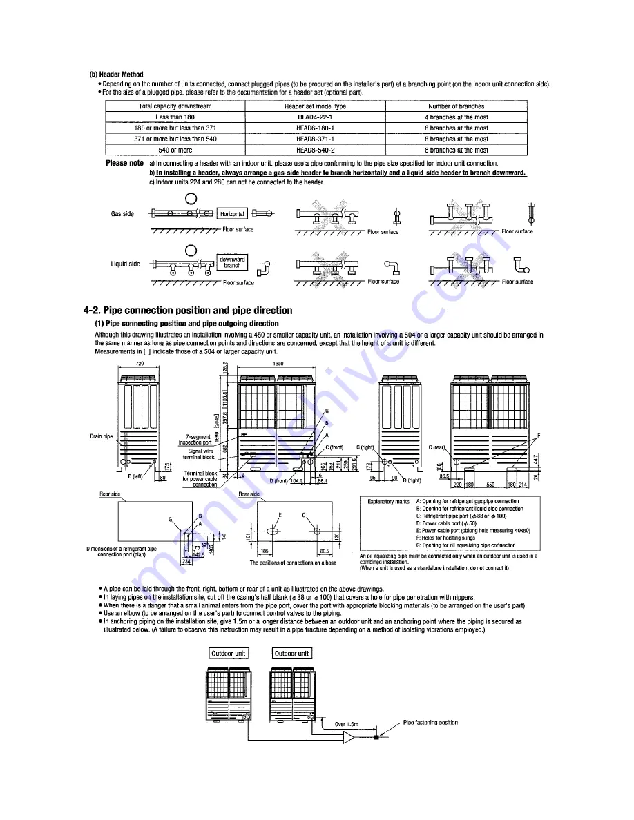
Page 214: ... 211 PSB012D855B 5 5 Instructions for installing the branch pipe set 2 I D φ25 4 O D φ28 58 100 P 9 I D φ34 92 O D φ38 1 100 P 15 I D φ25 4 O D φ28 58 100 P 9 I D φ34 92 O D φ38 1 100 P 15 DIS 540 2 ...

Page 215: ... 212 2 model type DIS model type HEAD ...

Page 216: ... 213 2 2 ...

Page 217: ... 214 2 2 2 2 2 ...

Page 218: ...eration Systems Headquarters 16 5 2 chome Kounan Minato ku Tokyo 108 8215 Japan Fax 03 6716 5926 Because of our policy of continuous improvement we reserve the right to make changes in all specifications without notice updated April 08 2009 updated May 11 2009 updated August 26 2009 ...

Reviews: