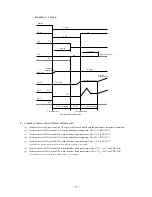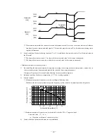
-
28
-
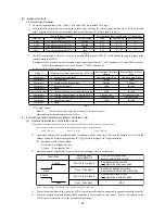
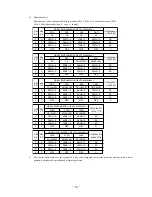
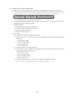
(3) Outdoor fan snow protection control (Master unit/Slave unit)
(Note) Following explanation is based on setting function with 7-segment display [C75].
However the following terminals and 7-segment function settings are available to use.
CnS1: [P11]-[5]
CnS2: [P12]-[5]
CnG1:
[P13]-[5]
CnG2:
[P14]-[5]
(a) The setting of this control should be done not only on the master unit but also on the slave unit, because the fans of master
unit and the slave unit are controlled independently.
(b) The control is enabled /disabled by selecting [0] or [1] displayed at 7-segement LED of master/slave units.
(c) Operation method of outdoor fan snow protection control
(i) Set the code [C75] on 7-segment display
(ii) “0” or “1” is displayed at the data display area of 7-segment LED.
“0”: Outdoor fan snow protection control is disabled (Factory setting)
“1”: Outdoor fan snow protection control is enabled
(iii) Press SW7 (Data write/delete) for 3 seconds continuously
(iv) “0” or “1” blinks every 0.5 second at the data display area of 7-segment LED.
(v) Press SW8 (one digit) to toggle the display between “0” and “1”.
(vi) If SW7 is pressed for 3 seconds continulouly while “0” and “1” are blinking, “0” or “1” at the data display area of
7-segment LED stops blinking.
With this operation, the enabled/disabled setting of outdoor fan snow protection control is saved in the memory of
EEPROM, and henceforth the outdoor fan is controlled according to the contents of memory.
(vii) Contents of outdoor fan snow protection control are retained even if the power is turned off and backed on again.
(d) Contents of outdoor fan snow protection control
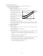
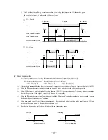
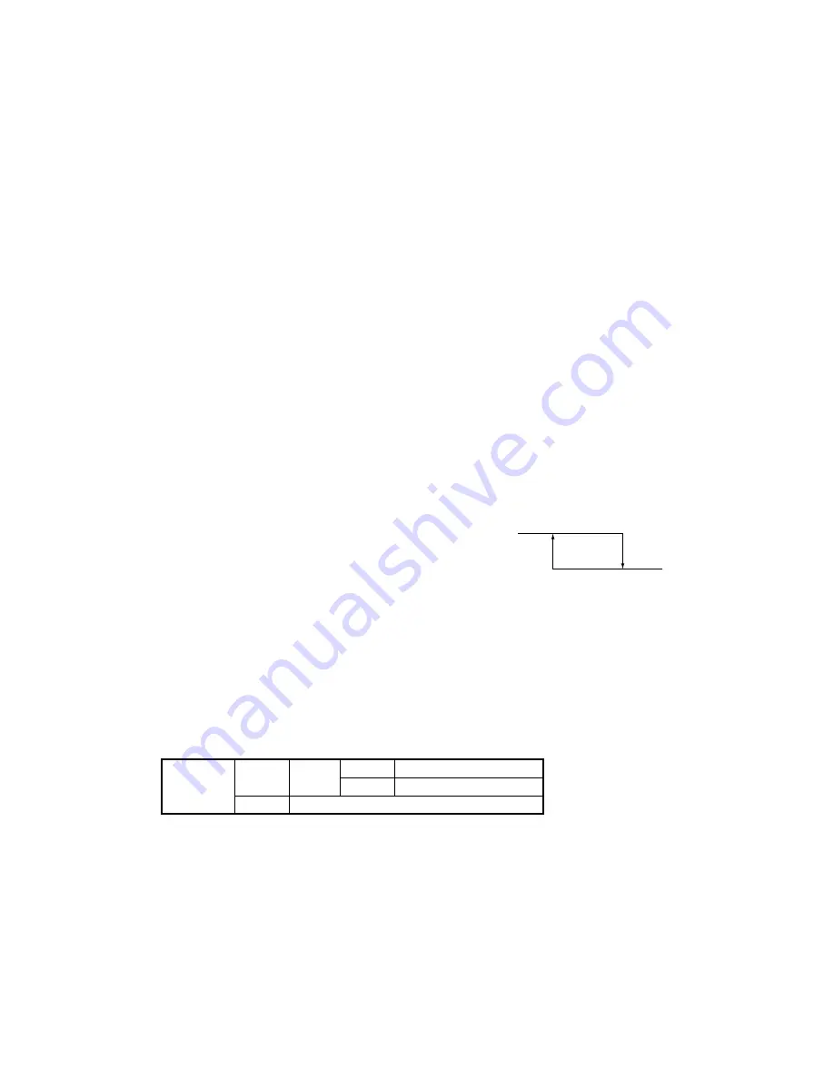
(i) At the status of all stop or emergency stop, if the outdoor air temperature drops 3°C or lower, all of outdoor fans are
operated at the maximum speed (4th speed) once every 10 minutes.
(ii) The outdoor fan runs for 30 minutes
(iii) During this snow protection control, the magnetic
contactor 52C1 of the compressor is ON
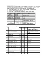
(4) Forced cooling /heating operation (Master unit)
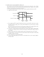
(Note) Following explanation is based on using CnG1 terminal and setting function [P13]-[2] with 7-segment display.
However other terminals can be used with following function setting of 7-segment display.
CnS1: [P11]-[2]
CnS2: [P12]-[2]
CnG2:
[P14]-[2]
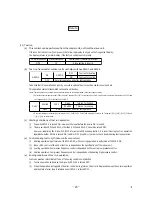
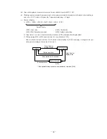
(a) When SW3-7 on the outdoor control PCB is turned ON after setting function [P13]-[2] with 7-segment display, if CnG1 is
shorted, forced heating operation is performed, but if CnG1 is open, forced cooling operation is performed.
(b) If the different mode from the forced operation mode is commanded from indoor unit, the "mode unmatch" message is
displayed on the LCD of remote controller and the operation is entered in FAN mode.
(5) Emergency stop control
When one of indoor units receives the emergency stop signal through CnT terminal on the indoor control PCB from the device
like as refrigerant leakage detector and that information is tarnsmitted to the outdoor unit, the outdoor unit stops opeartion and
emergency stop error message transmitted to all indoor units running.
It is able to make the emergency stop function effective by remote controller indoor function setting.
(a) When the outdoor unit receives the “Emergency stop” command from the indoor unit, it makes all stop by error.
(b) And the “Emergency stop” command is transmitted to all indoor units and error code “E63” is displayed.
(c) When the outdoor unit receives the “Emergency stop reset” command from the indoor unit, the “Emergency stop reset”
command is transmitted to all indoor units.
SW3-7
ON
CnG1
Open
Operation in cooling only
Shorted
Operation in heating only
OFF
Normal operation
3
5
Outdoor air temperature (°C)
Fan OFF
Fan ON
Summary of Contents for FDE112KXE6A
Page 104: ... 102 ...
Page 111: ... 108 b Ceiling cassette 4 way Compact type FDTC Models All moddels B PJA003Z331 ...
Page 112: ... 109 c Ceiling cassette 2 way type FDTW Models FDTW28KXE6 45KXE6 56KXE6 B PJB001Z560 ...
Page 113: ... 110 Models FDTW71KXE6 90KXE6 B PJB001Z561 ...
Page 114: ... 111 Models FDTW112KXE6 140KXE6 B PJB001Z562 ...
Page 115: ... 112 d Ceiling cassette 1 way type FDTS Model FDTS45KXE6 A PJC001Z195 ...
Page 116: ... 113 Model FDTS71KXE6 A PJC001Z196 ...
Page 117: ... 114 e Ceiling cassette 1 way compact type FDTQ Models All models A PJC001Z190 ...
Page 118: ... 115 Models All models Duct panel A PJC001Z240 ...
Page 121: ... 118 Models FDU224KXE6 280KXE6 B PJD001Z230 ...
Page 123: ... 120 Models FDUM112KXE6 140KXE6 B PJR002Z259 ...
Page 124: ... 121 h Duct connected Ultra thin Low static pressure type FDQS Models All models C PJC001Z200 ...
Page 125: ... 122 i Wall mounted type FDK Models FDK22KXE6 28KXE6 36KXE6 45KXE6 56KXE6 B PHA000Z983 ...
Page 126: ... 123 Models FDK71KXE6 B PHA000Z984 ...
Page 127: ... 124 j Ceiling suspended type FDE Models FDE36KXE6A 45KXE6A 56KXE6A B PFA003Z826 ...
Page 128: ... 125 Models FDE71KXE6A 112KXE6A 140KXE6A B PFA003Z827 ...
Page 129: ... 126 k Floor standing with casing type FDFL Models All models B PGD000Z053 ...
Page 130: ... 127 l Floor standing without casing type FDFU Models All models A PGD000Z058 ...
Page 131: ... 128 m Duct Connected Compact and Flexible type FDUH Models All models A PJC001Z255 ...
Page 138: ... 135 ...
Page 139: ... 136 ...
Page 143: ... 140 b ...
Page 144: ... 141 ...
Page 191: ... 188 5 4 Installation of outdoor unit ...
Page 193: ... 190 ...
Page 194: ... 191 ...
Page 195: ... 192 ...
Page 196: ... 193 ...
Page 197: ... 194 ...
Page 198: ... 195 ...
Page 199: ... 196 ...
Page 200: ... 197 ...
Page 201: ... 198 ...
Page 202: ... 199 ...
Page 203: ... 200 ...
Page 204: ... 201 ...
Page 205: ... 202 ...
Page 206: ... 203 ...
Page 207: ... 204 ...
Page 208: ... 205 ...
Page 210: ... 207 ...
Page 211: ... 208 ...
Page 212: ... 209 ...
Page 215: ... 212 2 model type DIS model type HEAD ...
Page 216: ... 213 2 2 ...
Page 217: ... 214 2 2 2 2 2 ...


