-
46
-
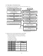
2.2 Explanation of troubleshooting
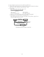
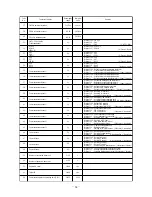
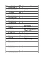
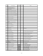
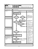
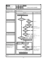
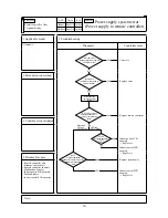
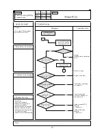
(a) Checking DC15V on the control PCB (Step to check if the inverter PCB fails or not)
Use this to diagnose E41, E42, E45 and E48.
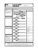
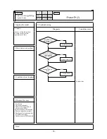
(b) Inspection of short-circuit on the power transistor module terminals
Disconnect the wiring of compressor and check for short-circuit with a tester.
Inspect between terminals of: P-U, P-V, P-W, N-U, N-V, N-W and P-N
It will be easier to contact the tester at the following place at each terminal.
P: P terminal of power transistor
N: N terminal of power transistor
U: End of red harness to compressor
V: End of white harness to compressor
W: End of blue harness to compressor
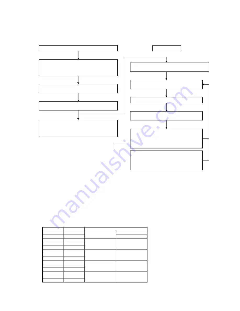
Power OFF (Power supply circuit breaker OFF)
Fan motor check
Even if DC15V is detected, affection by fan motor anomaly is
suspected. Implement following check.
*Be sure to check both fan motor 1 and 2
*After completion of checking both fan motor 1 and 2,
replace the anomalous fan motor.
Turn the power ON (power circuit breaker ON)
and start operation with the test run SW.
Check between #1 and #2 of CNI1 on the control
PCB to see if DC15V is detected.
Be sure to wait for 3 minutes after turning the
power circuit breaker off.
Disconnect the fan motor wires.
(Both the power cable and control wires)
Turn the power circuit breaker OFF
Wait 3 minutes
Check whether DC15V between
①
-
②
of CNI1
on the control PCB is detected.
Check
E41, 42, 45, 48
Connect the wires of fan motor 1 or 2
Power ON
Test run switch ON
If DC15V is detected, primary check is completed.
Return to
①
and check fan motor 2
(Between
①
-
③
of CNI3).
If no problem on both fan motor 1 and 2, go to further
diagnosis of E41, E42, E45, E48 sequentially.
If DC15V is not detected, the connected fan motor
has anomaly.
Turn the power OFF and disconnect the wires.
If the check of fan motor 2 is not completed, return to
①
and check fan motor 2 (Between
①
-
③
of CNI3).
Since, unless DC15V is detected, faulty inverter PCB is suspected,
check CNI1 at the control PCB side, the connector connection of
CNI2 at the inverter side and breakage of communication wires.
If everything is all right, replace the inverter PCB.
①
②
③
Terminal (+)
P
N
P
P
P
N
N
N
U
V
W
U
V
W
Terminal (--)
N
P
U
V
W
U
V
W
P
P
P
N
N
N
Normal value (
Ω
)
about 1M
about 300-400
0
about 1.2M
about 1.3M
0
Several 10 M
Several 10 M
Several 10 M
Several 100K
Several 100K
Several M
Note (1) When a measured value is 0 – a few k
Ω
, the element may be broken. Replace the power transistor part.
Summary of Contents for FDE112KXE6A
Page 104: ... 102 ...
Page 111: ... 108 b Ceiling cassette 4 way Compact type FDTC Models All moddels B PJA003Z331 ...
Page 112: ... 109 c Ceiling cassette 2 way type FDTW Models FDTW28KXE6 45KXE6 56KXE6 B PJB001Z560 ...
Page 113: ... 110 Models FDTW71KXE6 90KXE6 B PJB001Z561 ...
Page 114: ... 111 Models FDTW112KXE6 140KXE6 B PJB001Z562 ...
Page 115: ... 112 d Ceiling cassette 1 way type FDTS Model FDTS45KXE6 A PJC001Z195 ...
Page 116: ... 113 Model FDTS71KXE6 A PJC001Z196 ...
Page 117: ... 114 e Ceiling cassette 1 way compact type FDTQ Models All models A PJC001Z190 ...
Page 118: ... 115 Models All models Duct panel A PJC001Z240 ...
Page 121: ... 118 Models FDU224KXE6 280KXE6 B PJD001Z230 ...
Page 123: ... 120 Models FDUM112KXE6 140KXE6 B PJR002Z259 ...
Page 124: ... 121 h Duct connected Ultra thin Low static pressure type FDQS Models All models C PJC001Z200 ...
Page 125: ... 122 i Wall mounted type FDK Models FDK22KXE6 28KXE6 36KXE6 45KXE6 56KXE6 B PHA000Z983 ...
Page 126: ... 123 Models FDK71KXE6 B PHA000Z984 ...
Page 127: ... 124 j Ceiling suspended type FDE Models FDE36KXE6A 45KXE6A 56KXE6A B PFA003Z826 ...
Page 128: ... 125 Models FDE71KXE6A 112KXE6A 140KXE6A B PFA003Z827 ...
Page 129: ... 126 k Floor standing with casing type FDFL Models All models B PGD000Z053 ...
Page 130: ... 127 l Floor standing without casing type FDFU Models All models A PGD000Z058 ...
Page 131: ... 128 m Duct Connected Compact and Flexible type FDUH Models All models A PJC001Z255 ...
Page 138: ... 135 ...
Page 139: ... 136 ...
Page 143: ... 140 b ...
Page 144: ... 141 ...
Page 191: ... 188 5 4 Installation of outdoor unit ...
Page 193: ... 190 ...
Page 194: ... 191 ...
Page 195: ... 192 ...
Page 196: ... 193 ...
Page 197: ... 194 ...
Page 198: ... 195 ...
Page 199: ... 196 ...
Page 200: ... 197 ...
Page 201: ... 198 ...
Page 202: ... 199 ...
Page 203: ... 200 ...
Page 204: ... 201 ...
Page 205: ... 202 ...
Page 206: ... 203 ...
Page 207: ... 204 ...
Page 208: ... 205 ...
Page 210: ... 207 ...
Page 211: ... 208 ...
Page 212: ... 209 ...
Page 215: ... 212 2 model type DIS model type HEAD ...
Page 216: ... 213 2 2 ...
Page 217: ... 214 2 2 2 2 2 ...

