–
57
–
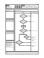
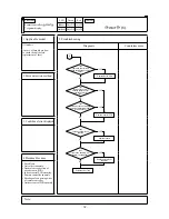
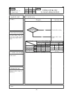
Error code
Remote controller:
7-segment display:
LED
Green
Red
Indoor
Outdoor
Content
WAIT
WAIT
(1)
Keeps flashing Stays Off
Keeps flashing Keeps flashing
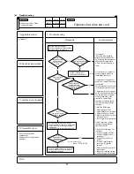
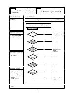
1. Applicable model
5. Troubleshooting
All models
(In case that is kept
on displaying on the remote
controller for more than 2
minutes after power ON)
Diagnosis
Countermeasure
NO
NO
NO
NO
NO
NO
NO
YES
NO
NO
YES
YES
YES
YES
YES
YES
YES
is kept on
displaying on the remote
controller for more than 2
minutes after power ON
Once turn OFF the breaker
and turn ON it again at 3
minute after power OFF
Isn't
the power fuse (5A) on the
outdoor control PCB
blown?
Is
the connection of wire
between noise filter and
inverter PCBs OK?
Are
the wires between indoor
and outdoor units
connected properly ?
Is
AC220-240V detected
between L-N at indoor
teminal block?
Is
AC380-415V detected
between L1-L2, L2-L3, L3-L1
respectively at outdoor
terminal block?
Does
indoor green LED keep
flashing?
Does
indoor green LED flash
2 times?
Is
AC380-415V detected at
the secondary side of
noise filter PCB terminal?
Does it become normal?
Replace fuse
WAIT
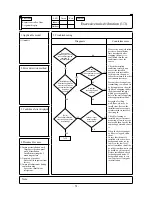
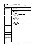
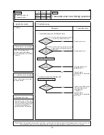
Refer next page
Replace noise filter PCB
Connect wires correctly
Indoor control PCB anomaly
Replace it
Indoor/outdoor control PCB
anomaly
Replace it
Remote controller anomaly
Replace it
Breakage of wires for remote
controller
Replace it
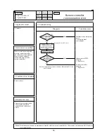
Correct the connecting wires
between indoor and outdoor
units
Outdoor control PCB anomaly
Replace it
Breakage of connecting wire
Noise
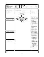
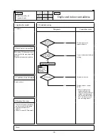
Indoor control PCB anomaly
Replace it
2. Error detection method
3.
Condition of error displayed
4. Presumable cause
• Fuse blown
• Noise filter anomaly
• Anomalous connection of
wire between PCBs
• Indoor control PCB anomaly
• Remote controller anomaly
• Breakage of connecting wires
of remote controller
• Outdoor control PCB anomaly
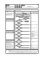
Note:
(1)
When anomaly occurs during establishing communication betweeen indoor and outdoor unit, error code E5 is displayed (outdoor red LED
flash 2-times)
In case of E5, the way of troubleshooting is same as above mentioned (except for checking of connecting wire)
When reset the power after E5 occurs, if this anomaly recurs, is displayed on remote controller. If power ON/OFF is repeated
in a short period (within 1 minute), may be displayed. In such case, please wait for 3 minute after the power breaker OFF.
(2) If any error is detected 30 minutes after displaying “ ” on the remote controller, the display changes to “INSPECT I/U”
WAIT
WAIT
WAIT
WAIT
Summary of Contents for FDE112KXE6A
Page 104: ... 102 ...
Page 111: ... 108 b Ceiling cassette 4 way Compact type FDTC Models All moddels B PJA003Z331 ...
Page 112: ... 109 c Ceiling cassette 2 way type FDTW Models FDTW28KXE6 45KXE6 56KXE6 B PJB001Z560 ...
Page 113: ... 110 Models FDTW71KXE6 90KXE6 B PJB001Z561 ...
Page 114: ... 111 Models FDTW112KXE6 140KXE6 B PJB001Z562 ...
Page 115: ... 112 d Ceiling cassette 1 way type FDTS Model FDTS45KXE6 A PJC001Z195 ...
Page 116: ... 113 Model FDTS71KXE6 A PJC001Z196 ...
Page 117: ... 114 e Ceiling cassette 1 way compact type FDTQ Models All models A PJC001Z190 ...
Page 118: ... 115 Models All models Duct panel A PJC001Z240 ...
Page 121: ... 118 Models FDU224KXE6 280KXE6 B PJD001Z230 ...
Page 123: ... 120 Models FDUM112KXE6 140KXE6 B PJR002Z259 ...
Page 124: ... 121 h Duct connected Ultra thin Low static pressure type FDQS Models All models C PJC001Z200 ...
Page 125: ... 122 i Wall mounted type FDK Models FDK22KXE6 28KXE6 36KXE6 45KXE6 56KXE6 B PHA000Z983 ...
Page 126: ... 123 Models FDK71KXE6 B PHA000Z984 ...
Page 127: ... 124 j Ceiling suspended type FDE Models FDE36KXE6A 45KXE6A 56KXE6A B PFA003Z826 ...
Page 128: ... 125 Models FDE71KXE6A 112KXE6A 140KXE6A B PFA003Z827 ...
Page 129: ... 126 k Floor standing with casing type FDFL Models All models B PGD000Z053 ...
Page 130: ... 127 l Floor standing without casing type FDFU Models All models A PGD000Z058 ...
Page 131: ... 128 m Duct Connected Compact and Flexible type FDUH Models All models A PJC001Z255 ...
Page 138: ... 135 ...
Page 139: ... 136 ...
Page 143: ... 140 b ...
Page 144: ... 141 ...
Page 191: ... 188 5 4 Installation of outdoor unit ...
Page 193: ... 190 ...
Page 194: ... 191 ...
Page 195: ... 192 ...
Page 196: ... 193 ...
Page 197: ... 194 ...
Page 198: ... 195 ...
Page 199: ... 196 ...
Page 200: ... 197 ...
Page 201: ... 198 ...
Page 202: ... 199 ...
Page 203: ... 200 ...
Page 204: ... 201 ...
Page 205: ... 202 ...
Page 206: ... 203 ...
Page 207: ... 204 ...
Page 208: ... 205 ...
Page 210: ... 207 ...
Page 211: ... 208 ...
Page 212: ... 209 ...
Page 215: ... 212 2 model type DIS model type HEAD ...
Page 216: ... 213 2 2 ...
Page 217: ... 214 2 2 2 2 2 ...

