-
60
-
'17 • PAC-T-256
Control box
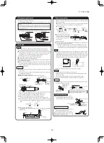
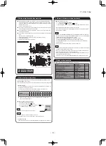
(b) Replacement procedure of the fan unit
Notes(1) The unit is a heavy item. It must be supported securely and handled with care not to drop when it is necessary to replace.
(2) For the maintenance space, refer to page 56.
(i) Models FDUM40VF, 50VF
1) Remove the control box and the side panel, and remove the
screws marked in the circles (2 places) in the figure.
(iii) Models FDUM100VF1, 125VF, 140VF
1) Remove the control box and the side panel, and remove the screws
marked in the circles (2 places) from the unit located at the near side.
2) Take out the fan unit in the arrow direction.
2) Take out the fan unit located at the near side in the arrow direction.
(ii) Model FDUM60VF
1) Remove the control box and the side panel, and remove the
screws marked in the circles (2 places) in the figure.
2) Take out the fan unit in the arrow direction.
3) Remove the screws marked in the circles (2 places) from the
fan unit located at the far side.
4) Take out the fan unit in the arrow direction.
Control box
Side panel
Screw
Screw
Control box
Side panel
Screw
Side panel
Screw
Control box
(b) Replacement procedure of the fan unit
Notes(1) The unit is a heavy item. It must be supported securely and handled with care not to drop when it is necessary to replace.
(2) For the maintenance space, refer to page 56.
(i) Models FDUM40VF, 50VF
1) Remove the control box and the side panel, and remove the
screws marked in the circles (2 places) in the figure.
(iii) Models FDUM100VF1, 125VF, 140VF
1) Remove the control box and the side panel, and remove the screws
marked in the circles (2 places) from the unit located at the near side.
2) Take out the fan unit in the arrow direction.
2) Take out the fan unit located at the near side in the arrow direction.
(ii) Model FDUM60VF
1) Remove the control box and the side panel, and remove the
screws marked in the circles (2 places) in the figure.
2) Take out the fan unit in the arrow direction.
3) Remove the screws marked in the circles (2 places) from the
fan unit located at the far side.
4) Take out the fan unit in the arrow direction.
Control box
Side panel
Screw
Screw
Control box
Side panel
Screw
Side panel
Screw

