background image

-

 3 

-

 '10 • PAC-SM-137

A

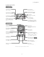
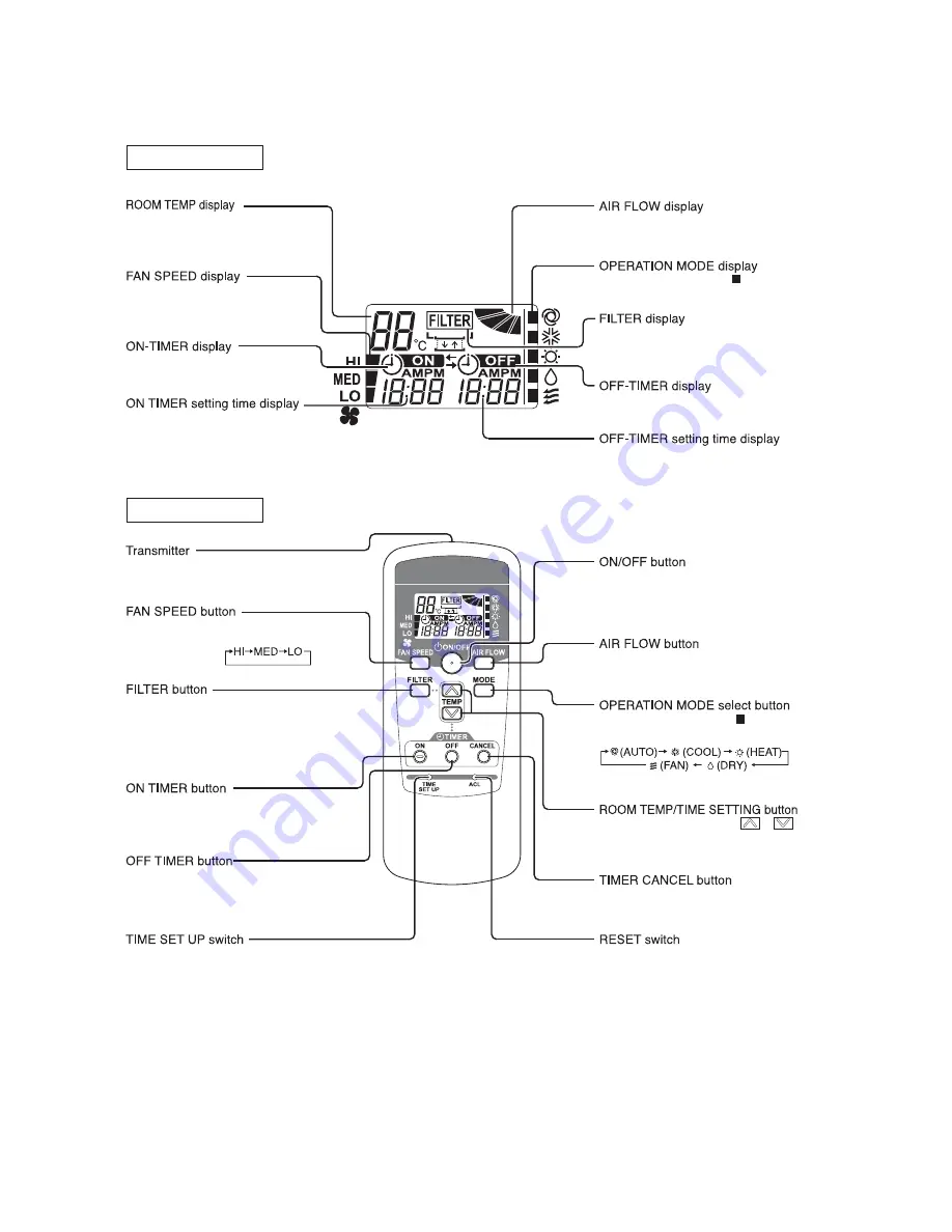
(2)   Wireless remote controller

FDEN series only

* All displays are described in the liquid crystal display for explanation

Indication section

Operation section

Indicates set temperature.

Indicates the status of swing louver.

Indicates selected operation with     .

Indicates for two seconds when FILTER 
button is pressed.

Indicates when OFF-TIMER is set.

Indicates OFF-TIMER setting time. Indicates the 
current time when the OFF-TIMER is not set.

When this is pressed once, the unit starts to 
operate and when this is pressed once again, 
it stops operating.

Used to swing the louver.

Every time this button is pressed,      displays switch 
as below.

Sets room temperature by pressing          or          button. 
Sets time when setting the time.

Used to cancel the TIMER SETTINGS.

Used to reset the microcomputer.

Indicates the selected airflow volume

Indicates when ON-TIMER is set.

Indicates the ON-TIMER setting time. 
Nothing displayed when ON-TIMER is 
not set.

Sends signal to the air conditioner.

Every time this button is pressed, the mode is 
switched as below.

Used to reset (turn off) the filter sign. 
Press the button only after completing 
the filter cleaning.

Sets ON TIMER operation.

Sets OFF TIMER operation.

Sets current time.

Summary of Contents for FDEN125VNXVD

Page 1: ...D FDT100VNXVD FDT100VSXVD FDT125VNXVD FDT125VSXVD FDT140VNXVD FDT140VSXVD Twin type SRK100VNXPZIX SRK100VSXPZIX SRK125VNXPZIX SRK125VSXPZIX Triple type SRK140VNXTZIX SRK140VSXTZIX WALL MOUNTED TYPE Twin type FDT71VNXPVD FDT100VNXPVD FDT100VSXPVD FDT125VNXPVD FDT125VSXPVD FDT140VNXPVD FDT140VSXPVD Triple type FDT140VNXTVD 140VSXTVD CEILING CASSETTE 4 WAY TYPE Single type FDEN71VNXVD FDEN100VNXVD FD...

Page 2: ...essed Invalid Operation is displayed but it does not mean a failure Cover AIR CON No button Display the indoor unit number connected to this remote controller CHECK button This button is used at servicing TEST button This button is used during test operation Weekly timer display Displays the settings of the weekly timer Operation setting display area Displays setting temperature airflow volume ope...

Page 3: ...rate and when this is pressed once again it stops operating Used to swing the louver Every time this button is pressed displays switch as below Sets room temperature by pressing or button Sets time when setting the time Used to cancel the TIMER SETTINGS Used to reset the microcomputer Indicates the selected airflow volume Indicates when ON TIMER is set Indicates the ON TIMER setting time Nothing d...

Page 4: ...peration mode Airflow volume mode Room temperature setting Louver auto swing stop However the stop position 4 position is cancelled so that it returns to Position 1 Remote controller function items which have been set with the remote controller function setting Indoor function items are saved in the memory of indoor unit Upper limit value and lower limit value which have been set with the temperatu...

Page 5: ...ger temperature C b Operations of functional items during cooling heating Cooling Heating Dehumidify Fan Operation Functional item Thermostat ON Thermostat ON Thermostat OFF Thermostat OFF Hot start Defrost Compressor 4 way valve Outdoor unit fan Indoor unit fan Louver motor Drain pump 3 2 2 Thermostat ON Thermostat OFF 2 2 Note 1 Operation Stop Turned ON OFF by the control other than the room tem...

Page 6: ...Power ON This is not displayed under the Remote mode 2 If this display is not shown under the Center Remote mode check if the indoor unit power switch is turned on or not f Hot start Cold draft prevention at heating At the startup of heating operation at resetting of the thermostat during defrost operation and at returning to heating the indoor fan is controlled by the indoor heat exchanger temper...

Page 7: ...tive i Filter sign As the operation time Total ON time of ON OFF switch accumulates to 180 hours 1 FILTER CLEANING is displayed on the remote controller This is displayed when the unit is in trouble and under the centralized control regardless of ON OFF Note 1 Time setting for the filter sign can be made as shown below using the indoor function of wired remote controller FILTER SIGN SET It is set a...

Page 8: ...umidifying operations to the fan or heating operation Stop 1 Indoor unit operation mode Control A Control B Compressor ON Compressor OFF Cooling Dehumidifying Heating Fan 2 Note 1 Including the stop from the cooling dehumidifying fan and heating and the anomalous stop 2 Including the Fan operation according to the mismatch of operation modes a Control A i If the float switch detects any anomalous d...

Page 9: ...ed If it is detected within further 15 minutes the indoor unit fan speed is raised by 1 tap more Note 1 Indoor unit fan speed can be increased by up to 2 taps iii FAN SPEED SW VALID INVALID of this control is selectable with the function setting of remote controller b In the case of FDT i When the indoor return air detection temperature detected with ThI A is 23 C or higher and the indoor heat exc...

Page 10: ...be better to set orderly like 0 1 2 F to avoid mistake 2 Display to the remote controller a Center or each remote controller basis heating preparation the youngest unit No among the operating units in the remote mode or the center mode unless the remote mode is available is displayed b Inspection display filter sign Any of unit that starts initially is displayed c Confirmation of connected units Pre...

Page 11: ...ition Unit stops 1 Only the LEVEL INPUT is acceptable for external input however when the indoor function setting of Level input Factory default or Pulse input is selected by the function for External input of the wired remote controller operation status will be changed as follows In case of Level input setting In case of Pulse input setting Unit operation from the wired remote controller becomes ...

Page 12: ...ration input connector CnT 6 is provided on the indoor control PCB However remote operation by CnT 6 is not effective when Center mode is selected by center controller In case of plural unit twin triple double twin remote operation input to CnT 6 on the slave indoor unit is invalid Only the LEVEL INPUT is acceptable for external input however when the indoor function setting of Level input Factory...

Page 13: ...controller system can be stopped operation Unit only Unit only Units Ⓝ Units Ⓝ When more than one indoor unit Max 16 indoor units are connected in one wired remote controller system 1 With the factory default external input to CnT 6 is effective for only the unit 2 When setting For all unit Local setting all units in one remote controller system can be controlled by external input to CnT 6 on the ...

Page 14: ...owever has the upper limit of 30 C Compressor Compressor Standard Operation Stop Setting temperature 1 1 Room temperature deg Operation Stop Setting temperature 2 4 Room temperature deg When it is set at 3 C x Return air temperature compensation This is the function to compensate the deviation between the detection temperature by the return air temperature thermistor and the measured temperature a...

Page 15: ...e is 18 C or higher 76 60 80 85 f Selection of max required frequency by heat exchanger temperature 1 Maximum required frequency is selected according to the outdoor unit heat exchanger temperature Tho R during cooling dehumidifying or according to the indoor unit heat exchanger temperature ThI R during heating mode 2 When there are 3 indoor unit heat exchanger temperatures ThI R whichever the hig...

Page 16: ...ncy operation control is performed during cooling dehumidifying Control contents a Starts with the compressor s target frequency at A rps When the outdoor air temperature Tho A is 35 C or higher it starts at C rps b At 30 seconds after the compressor start the compressor s target frequency is changed to B rps and the compressor s operation frequency is fixed for 10 minutes Model Operation mode A rp...

Page 17: ...one Outdoor unit heat exchanger temp C 20 30 zone 33 40 zone 43 53 zone c Fan tap control during heating operation Fan taps are selected depending on the outdoor unit heat exchanger temperature Tho R1 R2 and the outdoor air temperature Tho A Note 1 It is detected by Tho R1 or R2 whichever the lower zone zone zone zone Tap 3 Tap 3 Tap 4 zone Tap 3 Tap 4 5 Tap 5 zone Tap 4 Tap 5 Tap 6 Note 1 Value i...

Page 18: ...quency B rps c Power transistor radiator fin temperature C C 3 Control contents a Raises the outdoor unit fan tap by 1 tap b When the sampling is for 60 minutes and the value of power transistor radiator fin temperature Tho P is as follows When the power transistor radiator fin temperature Tho P C C the outdoor unit fan tap is raised by 1 speed further When C C power transistor radiator fin temperatu...

Page 19: ...2 Defrosting conditions B a When previous defrosting end condition is the time out of defrosting operation and it is in the heating operation after the cumulative compressor operation time after the end of defrosting has become 30 minutes b After 5 minutes from the start of compressor c After 5 minutes from the start of outdoor unit fan b Defrosting end conditions When any of the following conditi...

Page 20: ... with Tho D exceeds the setting value the compressor stops b When it is detected 2 times within 60 minutes or after continuous 60 minutes including the stop of compressor E36 is displayed on the remote controller and it enters the anomalous stop mode Compressor stop Compressor operation Discharge pipe temperature C 85 115 3 Reset of anomalous stop mode As it drops to the reset value of 85 C or low...

Page 21: ...nomalous stop control a When a value detected by the low pressure sensor LPT satisfies any of the following conditions the compressor stops to run for its protection When the low pressure drops to 0 079MPa or under for 15 seconds continuously At 10 minutes after the start of compressor the suction overheat becomes 30 C and the low pressure becomes 0 15MPa or under for 60 seconds continuously b E49...

Page 22: ...nutes E42 is displayed on the remote controller and it enters the anomalous stop mode j Anomalous inverter PCB If the power transistor detects any anomaly for 15 minutes including the stop of compressor E51 is displayed on the remote controller and it enters the anomalous stop mode k Anti frost control by the compressor frequency control 1 If the indoor unit heat exchanger temperature detected wit...

Page 23: ...within 40 minutes the compressor stops with the anomalous stop Note 1 During defrosting and for 3 minutes after the end of defrosting it is not detected Outdoor unit heat exchanger thermistor 50 C or lower Outdoor air temperature thermistor 45 or lower Low pressure sensor 0V or under or 4 0V or over 2 Discharge pipe temperature thermistor suction pipe temperature thermistor If the following is det...

Page 24: ...er supply is turned OFF Note 1 Value in are for the model 71 a Control contents 1 Close the operation valve at the liquid side It is left open at the gas side 2 Compressor is started with the target speed frequency at 71 62 100 55 125 140 45 rps in the cooling mode 3 Red and green lamps LED flash continuously on the outdoor unit control PCB 4 Each of protection and error detection controls excludin...

Page 25: ...A is 3ºC or lower In the heating mode When the compressor is turned ON 2 Drain pan heater OFF conditions When either one of following conditions is met the drain pan heater is turned OFF Outdoor air temperature detected with Tho A is 5ºC or higher When the compressor stop has been detected for 30 minutes continuously In the cooling or dehumidifying mode Drain pan heater ON Drain pan heater OFF Out...

Page 26: ...re short circuit Poor contact of temperature thermistor connector Replacement repair of temperature thermistor 72 Indoor control PCB Defective indoor control PCB Defective temperature thermistor input circuit Replacement of PCB 1 time flash Keeps flashing Stays OFF Keeps flashing Indoor return air temperature therm istor Defective indoor return air temperature thermistor defective element broken w...

Page 27: ...ngle phase modelonly Replacement of PCB or Repair 88 Stays OFF Keeps flashing 1 time flash Keeps flashing 1 time flash or 5 times flash Outdoor control PCB compressor Current cut Anomalous compressor over current Replacement of PCB 89 90 Installation or operating condition Service valve closing operation Repair Stays OFF Keeps flashing 1 time flash Keeps flashing Keeps flashing Outdoor control PCB...

Page 28: ...is detected for 5 15 seconds continuously within 60 minutes after initial detection of this anomalous temperature Indoor heat exchanger temperature thermistor anomaly 50 28 C or lower is detected for 5 15 seconds continuously within 60 minutes after initial detection of this anomalous temperature Or 70 C or higher is detected for 5 seconds continuously Outdoor Outdoor air temperature thermistor an...

Page 29: ...mit switch transformer and fuse Note 1 With regard to parts of high voltage circuits and refrigeration cycle judge it according to ordinary inspection methods b Instruction of how to replace indoor control PCB ٨ Read the SAFETY PRECAUTIONS carefully first of all and then strictly follow it during the replacement in order to protect yourself ٨ The precautionary items mentioned below are distinguish...

Page 30: ...㪼㫋㫋㫀㫅㪾 㪪㪮㪌 㪤㪸㫊㫋㪼㫉㪆㪪㫃㪸㫍㪼 㫊㪼㫋㫋㫀㫅㪾 㪪㪮㪎 㪝㫌㫅㪺㫋㫀㫆㫅㩷㫊㪼㫋㫋㫀㫅㪾 㪚㪥㪫䋨㪙㫃㫌㪼䋩 㪜㫏㫋㪼㫉㫅㪸㫃㩷㫊㫎㫀㫋㪺㪿 㪚㪥㪡㩿㪮㪿㫀㫋㪼䋩 㪣㫆㫌㫍㪼㫉㩷㫄㫆㫋㫆㫉 㪚㪥㪥㩿㪰㪼㫃㫃㫆㫎䋩 㪫㪿㪼㫉㫄㫀㫊㫋㫆㫉 㩿㪟㪼㪸㫋㩷㪼㫏㪺㪿㪸㫅㪾㪼㫉㪀 㪚㪥㪠㩿㪙㫃㫌㪼䋩 㪝㫃㫆㪸㫋㩷㪪㪮 㪚㪥㪟㩿㪙㫃㪸㪺㫂䋩 㪫㪿㪼㫉㫄㫀㫊㫋㫆㫉 㩿㪩㪼㫋㫌㫉㫅㩷㪸㫀㫉㪀 㪚㪥㪮㪊㩿㪩㪼㪻䋩 㪧㫆㫎㪼㫉㩷㪧㪚㪙 㪚㪥㪙㩿㪮㪿㫀㫋㪼䋩 㪩㪼㫄㫆㫋㪼 㪺㫆㫅㫋㫉㫆㫃㫃㪼㫉 㪚㪥㪭㪉㩿㪙㫃㪸㪺㫂㪀 㪘㫌㫋㫆㩷㫃㫀㪽㫋 㪚㪥㪞䋨㪙㫃㫌㪼䋩 㪚㪥㪱㩿㪮㪿㫀㫋㪼䋩 㪟㪘 㪚㪥㪜㩿㪮㪿㫀㫋㪼䋩 㪩㪘㪤㩷㪺㪿㪼㪺㫂㪼㫉 㪚㪥㪚㩿㪩㪼㪻䋩 㪟㫌㫄㫀㪻㫀㫋㫐 㫊㪼㫅㫊㫆㫉 㪚㪥㪮㪋㩿㪙㫃㫌㪼䋩 㪧㫆㫎㪼㫉㩷㪧㪚㪙 㪪㪮㪍 㪚㪸㫇㪸㪺㫀㫋㫐㩷㫊㪼㫋㫋㫀㫅㪾 㪚㪥㪭䋨㪩㪼㪻䋩 㪘㫌㫋㫆㩷㫃㫀㪽㫋...

Page 31: ...ector color should match with the color of connector of the PCB Note 2 6 Let the wiring red and blue pass beneath the yellow green wiring and bind together with band 7 Screw back the terminal of wiring yellow green from PCB T1䋬T2 T3 that was removed in 1 In that case do not place the crimping part of the wiring under the PCB Note 1 It might not be applicable on some models Note 2 After replacing P...

Page 32: ...㫌㪼㪀 㪘㪻㪻㫉㪼㫊㫊㩷㫊㪼㫋㫋㫀㫅㪾 㪪㪮㪌㩷㪤㪸㫊㫋㪼㫉㪆㪪㫃㪸㫍㪼 㫊㪼㫋㫋㫀㫅㪾 㪪㪮㪎 㪚㪥㪤㪊䋨㪮㪿㫀㫋㪼䋩 㪝㪸㫅㩷㫄㫆㫋㫆㫉 㪚㪥㪮㪈䋨㪮㪿㫀㫋㪼䋩 㪧㫉㫀㫄㪸㫉㫐㩷㫋㫉㪸㫅㫊㪽㫆㫉㫄㪼㫉 㪚㪥㪡㪉㩿㪙㫃㫌㪼䋩 㪣㫆㫌㫍㪼㫉㩷㫄㫆㫋㫆㫉 㪚㪥㪩㩿㪮㪿㫀㫋㪼䋩 㪛㫉㪸㫀㫅㩷㫇㫌㫄㫇 㪚㪥㪡㩿㪮㪿㫀㫋㪼㪀 㪣㫆㫍㪼㫉㩷㫄㫆㫋㫆㫉 㪧㫌㫃㫊㪼 㪚㪥㪠㩿㪙㫃㫌㪼䋩 㪝㫃㫆㪸㫋㩷㪪㪮 㪚㪥㪪㩿㪙㫃㫌㪼䋩 㪣㫆㫌㫍㪼㫉㩷㪪㪮 㪚㪥㪭㩿㪙㫃㪸㪺㫂䋩 㪘㫌㫋㫆㩷㫃㫀㪽㫋 㪚㪥㪟㩿㪙㫃㪸㪺㫂䋩 㪫㪿㪼㫉㫄㫀㫊㫋㫆㫉 㩿㪩㪼㫋㫌㫉㫅㩷㪸㫀㫉㪀 㪚㪥㪙㩿㪮㪿㫀㫋㪼䋩 㪩㪼㫄㫆㫋㪼 㪺㫆㫅㫋㫉㫆㫃㫃㪼㫉 㪚㪥㪮㪉㩿㪙㫃㪸㪺㫂䋩 㪪㪼㪺㫆㫅㪻㪸㫉㫐 㫋㫉㪸㫅㫊㪽㫆㫉㫄㪼㫉 㪚㪥㪥㩿㪰㪼㫃㫃㫆㫎䋩 㪫㪿㪼㫉㫄㫀㫊㫋㫆㫉 㩿㪟㪼㪸㫋 㪼㫏㪺㪿㪸㫅㪾㪼㫉㪀 㪚㪥㪫㩿㪙㫃㫌㪼䋩 㪦㫇㫋㫀㫆㫅 㪚㪥㪦㩿㪩㪼㪻...

Page 33: ...le 2 Model selection As per model See table 1 Remarks Address No setting at plural indoor units control by 1 R C 0 F Switches Description Default setting Master Slave setting Master Slave Table 1 Indoor unit model selection with SW6 1 SW6 4 0 OFF 1 ON 40V 50V 60V 71V 100V 125V 140V 1 1 1 1 1 0 1 1 0 1 0 1 0 0 0 1 1 0 0 1 1 0 0 0 1 1 1 1 SW6 4 SW6 1 SW6 2 SW6 3 Table 2 Indoor unit Master Slave sett...

Page 34: ...ng that voltage has been discharged sufficiently by measuring the voltage DC between both terminals of electrolytic capacitor C58 Measurment of voltage may be disturbed by the moisture proof coating In such case remove the coating and measure it by taking care of avoiding electrical shock a Module of part to be replaced for outdoor unit controller Outdoor control PCB Inverter PCB Temperature therm...

Page 35: ...H CNR CNS CNN CNFAN CNEEV2 CNPS CNA2 1 Model FDC71VNX a Replace the PCB after elapsing 3 minutes from power OFF Be sure to measure voltage DC between T26 and T27 on inverter PCB and check that the voltage is discharged sufficiently 10V or less Refer to Fig 1 b Disconnect the connectors from the control PCB c Match the switches setting SW4 with the former PCB d Connect the connectors to the control...

Page 36: ...efore replacing the PCB e Match the setting switches SW3 5 JSW SW J5 7 with the former PCB f Tighten up a screw after passing white or blue wiring through CT1 of the changed g Please connect the connectors with the same place Confirm the connectors are not half inserted PCA012D024F H after elapsing 3 minutes from power OFF 㩷 connectors are not half inserted Parts Arrangement View CNA2 CNIP CNTH CN...

Page 37: ...rged sufficiently 10V or less Refer to Fig 1 b Take off the connection of inverter PCB terminal and connector and remove the screw of power transistor IC10 active filter IC2 and diode stack DS1 then remove the PCB Wipe off the silicon grease neatly on the controller s radiation heat fins Refer to Fig 1 and Parts arrangement view c Refer to table1 for the setting of switch JSW10 11 of new PCB d Bef...

Page 38: ...FF SW5 3 OFF SW5 4 OFF J5 With J7 With Default setting Outdoor fan control when ducting Normal Hi tap Valid Normal Valid Invalid Keep OFF Keep OFF Keep OFF Keep OFF Keep OFF Keep OFF Reserved Overseas See table 1 Model selection 3 phase Single phase As per model Model selection Domestic Overseas Normal Test run mode Cooling Heating Cooling Test run SW Normal Test run Normal Snow protection control...

Page 39: ...5䋬䋨㪍䋩 a 2 3 Current safe control of inverter primary current P 27䋬䋨㪍䋩 g 4 High pressure protection control P 25䋬䋨㪍䋩 b 1 䋬P 26䋬䋨㪍䋩 c 1 5 High pressure anomaly P 25䋬䋨㪍䋩 b 2 6 Low pressure protection control P 26䋬䋨㪍䋩 e 1 䇭 7 Low pressure anomaly P 26䋬䋨㪍䋩 e 2 8 Anti frost prevention control P 27䋬䋨㪍䋩 k 9 Current cut P 27䋬䋨㪍䋩 g 10 Power transistor protection control P 27䋬䋨㪍䋩 h 11 Power transistor anomal...

Page 40: ...operation 0 5 seconds lighting 0 5 seconds stays OFF At the time of anomalous 2 seconds lighting 1 second stays OFF Filter sign TIMER RUN CHECK 2 FDT Wireless kit TIMER CHECK RUN Romote controller signal receiving part Backup switch Check monitor Error code display E1 E60 Operation display light Green Lights continuously Under air conditioner operation Keeps flashing Under heating preparation At t...

Page 41: ...P Power transistor P terminal N Power transistor N terminal U End of red harness to compressor V End of white harness to compressor W End of black or blue harness to compressor Check for a power transistor short circuit When you do not have a diagnostic checker for judging if the inverter is defective measure between the terminals of the power transistor parts judge whether the power transistor is...

Page 42: ...ve the terminal cover of compressor and disconnect the wires U V W from compressor 3 Connect the wires U Red V White and W Black of checker to the terminal of disconnected wires U V W from compressor respectively b Operation for judgment 1 Power ON after JSW10 4 on outdoor inverter PCB was turned ON 2 After 15 seconds since power has turned ON LED start ON OFF for 5 seconds cyclically and it repea...

Page 43: ...oints Check items with the mark when the power is ON LED1 Green LED2 Red Power supply check Measure the power supply at L N It is normal if it is AC 220 240V Noise filter check There should be continuity There should be no shorts between phase Must be conductive When fuse is blown replace it or check wiring LED2 Red check 1 5 time flash Refer to page 32 No anomaly like breakage swell etc allowed V...

Page 44: ...PT CNTH CNB CNIP CNW CNW2 CNE CNH CNR CNS CNEEV1 CNEEV2 CNFAN1 CNA1 CNI3 CNI1 18V 15V FMO1 M M M SM2 SM1 20S CNF OPTION DH CH1 THo R2 THo P THo A THo S THo D THo R1 Power supply check Measure the power supply L1 N It is normal if it is AC220 240V Noise filter check There should be continuity There should be no shorts between phases DC Reactor continuity Check Max 25mǡ Capacitor check Check for ano...

Page 45: ...S NO NO Is the compressor operating NO YES NO Note 1 Outdoor 35 C Indoor 27 C 1 WAIT It is normal This unit is designed to start in the soft start mode by detecting the under dome temperature of compressor when it restart after power reset It is necessary to replace to higher capacity one or to install additional unit Compressor refrigerant oil protection control at starting is activated For the c...

Page 46: ...r operating NO YES NO Note 1 Outdoor 7 C Indoor 20 C 1 WAIT It is normal This unit is designed to start in the soft start mode by detecting the under dome temperature of compressor when it restart after power reset It is necessary to replace to higher capacity one or to install additional unit Compressor refrigerant oil protection control at starting is activated For the contents of control refer ...

Page 47: ...gerant migrated in the compressor When the earth breaker is activated at lower insulation resistance check the following points 6 hours after power ON check if the insulation resistance recovers to normal When power ON crankcase heater heat up compressor and evaporate the refrigerant migrated in the compressor Check if the earth leakage breaker is conformed to higher harmonic regulation or not Sin...

Page 48: ... by fixing pipes on the wall or wrapping rubber cushion around the pipe which goes through the hole in the wall or applying other appropriate means Strength of ceiling wall floor etc may be insufficient Review the installing position or reinforce it Check for leaning of installed unit or anomalous mounting of fan louver or motor and specify the contacting point and correct it When the heat exchang...

Page 49: ...ing or defrosting in the heating mode It is normal The noise vibration occurs when the refrigerant starts or stops flowing It is normal When the defrosting starts or stops during heating the refrigerant flow is reversed due to switching 4 way valve This causes a large change in pressure which produces a blowing sound It may accompany also the hissing sounds as mentioned above They are normal After...

Page 50: ...cuum dry and recharge refrigerant Since there could be many causes of noise vibration the above do not cover all In such case check the conditions when where how the noise vibration occurs according to following check point Indoor outdoor unit Cooling heating fan mode Startup stop during operation Operating condition Indoor outdoor temperatures pressure Time it occurred Operation data retained by ...

Page 51: ...the louver operable with the remote controller YES NO Does the louver operate at the power on YES NO YES NO Operate after waiting for more than 1 minute Repair wiring Defective indoor control PCB ª Replace Replace LM Normal Adjust LM lever and then check again 2 Error detection method 3 Condition of Error displayed 4 Presumable cause Defective LM LM wire breakage Faulty indoor control PCB Note Err...

Page 52: ... 3 phase unit detected between 1 2 and 3 on the teminal block of outdoor unit or isAC220 240V for 1 phase unit detected between 1 and 2 on the terminal block of outdoor unit YES YES YES YES Is JX1 open Is JX1 open Defective outdoor control PCB Noise filter Misconnection or breakage of connecting wires Defective indoor control or power PCB ª Replace Replace FM LM etc Replace fuse Defective indoor p...

Page 53: ...O Is DC15V or higher detected between X Y of indoor unit terminal block FDEN FDUM FDU Series FDT FDTC Series YES YES YES YES NO NO YES NO NO Correct Replace wires Replace remote controller Defective indoor power PCBªReplace Defective indoor control PCBªReplace Replace transformer Defective indoor control PCBªReplace 2 Error detection method 3 Condition of Error displayed 4 Presumable cause Remote ...

Page 54: ...t NO YES YES NO NO NO NO NO YES YES YES Set one remote controller for Master and the other for Slave Set SW1 on remote controller PCB at Master Set address again SW2 on indoor control PCB Separate remote controller wires from high voltage wires Defective indoor control PCBªReplace Defective remote controller ªChange 2 Error detection method Communication between indoor unit and remote controller i...

Page 55: ... 4 Presumable cause Improper setting Surrounding environment Defective remote controller communication circuit Faulty indoor control or power PCB Faulty outdoor control PCB Note If any error is detected 30 minutes after displaying WAIT on the remote controller the display changes to INSPECT I U NO NO NO NO NO Are more than 3 units of remote controller connected Does remote controller display Slave...

Page 56: ...it terminal block Is approx DC20V detected between on the indoor unit terminal block WAIT See next page Defective indoor control PCBªReplace Defective indoor control PCBª Replace Defective remote controllerªReplace Broken remote controller wire Yª Replace Correct connection wires between indoor and outdoor units Defective outdoor control PCBªReplace Defective connection wire Broken Noise Defective...

Page 57: ...ilter secondary side Isn t fuse 250V 2A on the outdoor control PCB blown NO YES Is DC5V detected on the outdoor control PCB Between of CNI1 NO YES Is DC5V detected if the connector of outdoor unit fan motor is disconnected NO Is DC255 310V detected at CNA2 1 Normal Malfunction by noise See next page Replace noise filter Check connection of diode stack and electrolytic capacitor by refering main el...

Page 58: ...e electrolytic capacitor NO Replace the power supply fuse YES Isn t there a short circuit between phases of the noise filter Isn t there a short circuit between phases of inverter PCB input terminals Isn t there any crack burning on the power transistor module Is the reactor OK Is the electrolytic capacitor OK 2 Error detection method 3 Condition of Error displayed 4 Presumable cause Blown fuse Fa...

Page 59: ...ler wires if the remote controller is removed Are wires connected properly between the indoor outdoor units NO Defective remote controller Defective remote controller Defective connecting wire Defective remote controller wire Short circuit etc Defective indoor control PCBªReplace 2 Error detection method 3 Condition of Error displayed 4 Presumable cause Faulty indoor control PCB Defective remote c...

Page 60: ...al environment Defective indoor control PCB ª Replace Defective remote controller ª Replace 2 Error detection method When normal communication between the remote controller and the indoor unit is interrupted for more than 2 minutes Detectable only with the remote controller 3 Condition of Error displayed Same as above 4 Presumable cause Defective communication circuit between remote controller ind...

Page 61: ...ase that the outdoor unit red LED flashes 2 times Repair signal wires Repair signal wires To the diagnosis of WAIT Unit is normal Malfunction by temporary noise etc Defective outdoor control PCB Defective network communication circuit ª Replace Unit is normal Malfunction by temporary noise etc 2 Error detection method When normal communication between indoor and outdoor unit is interrupted for mor...

Page 62: ...eat exchanger temperature thermistor input circuit 2 Error detection method Anomalously low temperature or high temperature resistance is detected on the indoor heat exchanger thermistor ThI R1 R2 or R3 3 Condition of Error displayed When the temperature thermistor detects 50 28 C or lower for 5 15 seconds continuously the compressor stops After 3 minutes delay the compressor starts again automati...

Page 63: ...l PCB ª Replace Defective return air temperature thermistor input circuit 2 Error detection method Anomalously low temperature or high temperature resistance is detected by indoor return air temperature thermistor Thi A 3 Condition of Error displayed When the temperature thermistor detects 50 45 C or lower for 5 15 seconds continuously the compressor stops After 3 minute delay the compressor start...

Page 64: ... see the error display E6 YES NO YES NO Error stop Reset Indoor heat exchanger temperature C 56 63 Wash Defective indoor heat exchanger temperature thermistor connectorª Correct Defective indoor heat exchanger temperature thermistor Check refrigerant system Adjust 2 Error detection method Indoor heat exchanger temperature thermistor ThI R1 R2 R3 3 Condition of Error displayed When it is detected 5...

Page 65: ...door control PCB ª Replace Defective indoor control PCB ª Replace Check optional equipment Correct setting to Humidifier DM interlock Defective indoor control PCB ª Replace Replace power PCB on FDT and FDTC Series Check wiring of Drain motor Correct Check drain motor 2 Error detection method Float switch is activated 3 Condition of Error displayed If the float switch OPEN is detected for 3 seconds...

Page 66: ... 17 indoor units connected to one remote controller NO YES Defective remote controller ª Replace Reduce to 16 or less units 2 Error detection method When it detects more than 17 of indoor units connected to one remote contorller 3 Condition of Error displayed Same as above 4 Presumable cause Excessive number of indoor units connected Defective remote controller Note Error code Remote controller LE...

Page 67: ... supply Note 1 Set dip switches SW5 1 and SW5 2 as shown in the following table Factory default setting Master Master Slave a Slave b Slave c SW5 1 OFF OFF ON SW5 2 OFF ON OFF ON ON Dip switch Indoor unit YES NO NO YES Correct unit address setting Correct wiring Defective indoor control PCB Replace Malfunction by noise Check surrounding environment 2 Error detection method When communication error...

Page 68: ...eplace fan motor If the error persists after replacing the fan motor replace the indoor control PCB Malfunction by temporary noise 2 Error detection method Detected by rotation speed of indoor fan motor 3 Condition of Error displayed When actual rotation speed of indoor fan motor drops to lower than 200rpm for 30 seconds continuously the compressor and the indoor fan motor stop After 2 seconds it ...

Page 69: ...ntrol PCB Defective SW7 ªReplace Turn SW7 1 on the indoor control PCB OFF and reset the power 2 Error detection method After indoor operation check when the communication between indoor and outdoor unit is established and SW7 1 is still kept ON 3 Condition of Error displayed Same as above 4 Presumable cause Mistake in SW7 1 setting Due to forgetting to turn OFF SW7 1 after indoor operation check N...

Page 70: ...e Faulty connection of remote controller temperature thermistor Defective remote controller temperature thermistor Defective remote controller PCB Note After 10 seconds has passed since remote controller thermistor was switched from valid to invalid E28 will not be displayed even if the thermistor harness is disconnected At same time the thermistor which is effective is switched from remote contro...

Page 71: ...roperly NO NO YES Check power supply Replace noise filter Connect properly Defective outdoor control PCBªReplace 2 Error detection method When 0V is detected on any of L1 L2 L3 for 5 seconds continuously after turning power on 3 Condition of Error displayed Same as above 4 Presumable cause Anomalous power supply Blown power supply fuse Defective noise filter Defective wire connection on noise filt...

Page 72: ...rmistor Check unit side Isn t the air circulation of outdoor unit short circuited Are installation spaces adequate Isn t there any fouling or clogging on heat exchanger Control operation check Defective outdoor control PCBªReplace Excessive refrigerant amount Recharge refrigerant by weighing proper amount on a scale 2 Error detection method For the error detection method refer to the protective co...

Page 73: ...weighing proper amount on a scale Control operation check Defective outdoor control PCBªReplace Check unit side Isn t filter clogged Are adequate indoor outdoor unit installation spaces Isn t there any short circuit of air Isn t there any fouling clogging on indoor heat exchanger 2 Error detection method For the error detection method refer to the protective control by controlling compressor rotat...

Page 74: ...e outdoor control PCBªReplace Defective outdoor heat exchanger temperature thermistor input circuit 2 Error detection method Detection of anomalously low temperature resistance on the outdoor heat exchanger temperature thermistor 3 Condition of Error displayed When the temperature thermistor detects 50 C or lower for 20 seconds continuously within 2 minutes to 2 minutes 20 seconds after the compre...

Page 75: ... PCBªReplace Defective outdoor air temperature thermistor input circuit 2 Error detection method Detection of anomalously low temperature resistance on outdoor air temperature thermistor 3 Condition of Error displayed When the temperature thermistor detects 45 C or lower for 5 seconds continuously within 2 minutes to 2 minutes 20 seconds after the compressor ON the compressor stops After 3 minutes...

Page 76: ...ance characteristics Temperature thermistor resistance k7 Temperature C Broken wire Shot circuit Correct connector Defective discharge pipe temperature thermistorª Replace Defective outdoor control PCBªReplace Defective temperature thermistor input circuit 2 Error detection method Detection of anomalously low temperature resistance on the discharge pipe temperature thermistor 3 Condition of Error ...

Page 77: ...n OK YES YES If the power supply breaker is turned OFF and ON too quickly E40 may be displayed This is normal NO YES If any anomaly exists on the electronic expansion valve connector connection the power supply must be reset NO Open service valve Correct 63H1 connector Correct electronic expansion valve connector Defective outdoor control PCBªReplace Defective 63H1 input circuit 2 Error detection ...

Page 78: ...20 140 160 180 200 0 20 40 60 80 100 120 140 Temperature C Temperature thermistor resistance k NO Temperature resistance characteristics NO NO NO NO Fixed screw Application of radiation silicone YES Shot circuit Broken wire OK Replace power transistor Fix properly OK 2 Error detection method Anomalous rise of the internal power transistor temperature 3 Condition of Error displayed When anomalous r...

Page 79: ...FDC100 140VSX NO NO NO Check power supply Open the valves Check refrigerant amount and refregerant circuit In case of transitional increase of high pressure and or test run several times restarting may recover it because liquid refrigerant migrated in the compresser is discharged from the compressor Replace compressor 2 Error detection method In order to prevent from overcurrent of inverter if the...

Page 80: ...on pipe temperature thermistor normal Is there any anoumalous sound on the compressor YES Continue from previous page YES Defective inverter PCBª Replace Defective inverter PCBª Replace 2 Error detection method In order to prevent from overcurrent of inverter if the current exceeds the specifications it makes the compressor stopping 3 Condition of Error displayed If the output current of inveter e...

Page 81: ...erly Is normal state restored YES NO NO NO Correct connector Change to OFF Check why power is not supplied to inverter PCB Defective fan motor Connect communication wire securely Defective inverter PCBª Replace OK 2 Error detection method 3 Condition of Error displayed When communication is not established between the inverter PCB and the outdoor control PCB 4 Presumable cause Defective inverter P...

Page 82: ...e 2 Error detection method In order to prevent from overcurrent of A F if the current exceeds the specifications it makes the compressor stopping 3 Condition of error displayed If the output current of A F exceeds the specifications it makes the compressor stopping 4 Presumable cause Defective inverter PCB Note Error code Remote controller LED Green Red Outdoor control PCB Outdoor Inverter PCB 1 t...

Page 83: ... 30 minutes continuously the compressor and the outdoor fan motor stop After 3 minutes delay it starts again automatically but if this anomaly occurs 5 times within 60 minutes after the initial detection 4 Presumable cause Defective outdoor control PCB Foreign material at rotational area of fan propeller Defective fan motor Dust on outdoor control PCB Blow fuse External noise surge Note When E48 e...

Page 84: ...trol PCBªReplace Replace low pressure sensor 2 Error detection method Detected by low pressure drop and suction superheat 3 Condition of Error displayed When the low pressure sensor detects 0 079MPa or lower for 15 seconds continuously compressor stops and it restarts automatically after 3 minutes delay And if this anomaly occurs 3 times within 60 minutes 10 minutes after the compressor starts if ...

Page 85: ...re sensor suction pipe temperature thermistor OK Is the low pressure normal during operation Continued from previous page Open fully Correct Defective low pressure sensor suction pipe temperature thermistorª Replace Charge refrigerant Defective outdoor control PCBªReplace Defective low pressure sensor suction pipe temperature thermistor circuits 2 Error detection method 3 Condition of Error displa...

Page 86: ...er PCBª Replace Broken harness wire Replace fan motor Defective outdoor control PCBªReplace 2 Error detection method When power transistor anomaly is detected for 15 minutes continuously 3 Condition of Error displayed Same as above 4 Presumable cause Defective outdoor fan motor Defective inverter PCB Defective outdoor control PCB Note Error code Remote controller LED Green Red Outdoor control PCB ...

Page 87: ...door control PCBªReplace Defective suction pipe temperature thermistor input circuit 2 Error detection method When the suction pipe temperature thermistor detects anomalously low temperature 3 Condition of Error displayed If the temperature thermistor detects 50 C or lower for 5 seconds continuously within 10 minutes to 10 minutes 20 seconds after compressor ON the compressor stops When the compre...

Page 88: ... Defective low pressure sensor input circuit OK 2 Error detection method When anomalous voltage pressure is detected 3 Condition of Error displayed If the pressure sensor detects 0V or lower and 3 49V or higher for 5 seconds continuously within 2 minutes to 2 minutes 20 seconds after compressor ON the compressor stops When the compressor is restarted automatically after 3 minuts delay if this anom...

Page 89: ...ror detection method Judge insufficient refrigerant amount by detecting the temperature differnce between indoor heat exchanger ThI R and indoor return air ThI A It detects at initial startup in cooling or dehumidifying mode after power ON In case of model 71 it cannot detect 3 Condition of Error displayed When the insufficient refrigerant amount is detected 3 times within 30 minutes In case of Mo...

Page 90: ...of compressor motor If the compressor speed cannot increase 11Hz or higher 3 Condition of Error displayed If compressor fails to startup for 20 times 10 patterns x 2 times It is availabel to reset by remote controller after 3 minutes delay 4 Presumable cause Faulty outdoor fan motor Faulty inverter PCB Anomalous power supply voltage Improper refrigerant amount and refrigerant circuit Faulty compre...

Page 91: ...eck joint Accumlator Check valve Thermistor ThO R2 㱢9 52 Gas line 㱢15 88 Liquid line 1 Single type Model 71 Thermistor Return air ThI A Thermistor Heat exchanger ThI R3 Thermistor Heat exchanger ThI R2 Thermistor Heat exchanger ThI R1 Heat exchanger Indoor unit Outdoor unit Flare connecting Flare connecting Thermistor ThO D Thermistor ThO S Thermistor ThO A Cooling cycle Heating cycle Thermistor T...

Page 92: ...part or center upper part Cut off the upper thin part of remote controller lower case with a nipper or knife and grind burrs with a file etc Install the lower case to the flat wall with attached two wooden screws WARNING CAUTION Fasten the wiring to the terminal securely and hold the cable securely so as not to apply unexpected stress on the terminal Loose connection or hold will cause abnormal he...

Page 93: ...te is as shown in the right diagram depending on the pulling out direction The wiring inside the remote controller case should be within 0 3mm2 recommended to 0 5mm2 The sheath should be peeled off inside the remote controller case The peeling off length of each wire is as below Pulling out from upper left Pulling out from upper center X wiring 215mm Y wiring 195mm X wiring 170mm Y wiring 190mm In...

Page 94: ...temperature set How to set upper and lower limit value 1 Stop the air conditioner and press SET and MODE button at the same time for over three seconds The indication changes to FUNCTION SET 2 Press button once and change to the TEMP RANGE indication 3 Press SET button and enter the temperature range setting mode 4 Select UPPER LIMIT or LOWER LIMIT by using button 5 Press SET button to fix 6 When ...

Page 95: ...n in the four The louver can stop at any position In normal working indication indoor unit temperature is indicated instead of airflow Only the master remote controller can be indicated Heating preparation indication should not be indicated Temperature indication is by degree C Temperature indication is by degree F ON OFF button finished Start Stop air conditioner and press SET and MODE buttons at...

Page 96: ...rease in return air temperature of indoor unit To be reset producing 1 0 C increase in return air temperature of indoor unit To be reset producing 1 0 C increase in return air temperature of indoor unit To be reset producing 1 5 C increase in return air temperature of indoor unit To be reset producing 2 0 C increase in return air temperature of indoor unit When heating thermostat is OFF fan speed ...

Page 97: ... No and function are indicated by turns on the remote controller function table then you can select from them For example Press or button Select the setting Press or button Select the setting The current setting of selected function is indicated for example AUTO RUN ON If 02 AUTO RUN SET is selected Press SET button Press SET button Press or button Press or button Select the number of the indoor u...

Page 98: ...DF WBMWFT GPS MJRVJE MJOF BOE HBT MJOF VOUJM DPNQMFUFE SFGSJHFSBOU QJQJOH XPSL BJS UJHIUOFTT UFTU BOE FWBDVBUJPO G UIF DPNQSFTTPS JT PQFSBUFE JO TUBUF PG PQFOJOH TFSWJDF WBMWFT CFGPSF DPNQMFUFE DPOOFDUJPO PG SFGSJHFSBOU QJQJOH XPSL ZPV NBZ JODVS GSPTU CJUF PS JOKVSZ GSPN BO BCSVQU SFGSJHFSBOU PVUnPX BOE BJS DBO CF TVDLFE JOUP SFGSJHFSBOU DJSDVJU XIJDI DBO DBVTF CVSTU PS QFSTPOBM JOKVSZ EVF UP BOPN...

Page 99: ...BMMFE JU DBO DBVTF mSF PS FMFDUSJD TIPDLT P OPU VTF BOZ NBUFSJBMT PUIFS UIBO B GVTF XJUI UIF DPSSFDU SBUJOH JO UIF MPDBUJPO XIFSF GVTFT BSF UP CF VTFE POOFDUJOH UIF DJSDVJU XJUI DPQQFS XJSF PS PUIFS NFUBM UISFBE DBO DBVTF VOJU GBJMVSF BOE mSF P OPU JOTUBMM UIF VOJU OFBS UIF MPDBUJPO XIFSF MFBLBHF PG DPNCVTUJCMF HBTFT DBO PDDVS G MFBLFE HBTFT BDDVNVMBUF BSPVOE UIF VOJU JU DBO DBVTF mSF P OPU JOTUBM...

Page 100: ...Z IFBU SBEJBUJPO GSPN PUIFS IFBU TPVSDF 〇 QMBDF XIFSF TOPX XJMM OPU BDDVNVMBUF 〇 QMBDF XIFSF UIF VOJU DBO CF LFQU BXBZ N PS NPSF GSPN 57 TFU BOE PS SBEJP SFDFJWFS JO PSEFS UP BWPJE BOZ SBEJP PS 57 JOUFSGFSFODF 〇 QMBDF XIFSF HPPE BJS DJSDVMBUJPO DBO CF TFDVSFE BOE FOPVHI TFSWJDF TQBDF DBO CF TFDVSFE GPS NBJOUFOBODF BOE TFSWJDF PG UIF VOJU TBGFMZ 〇 QMBDF XIFSF UIF VOJU XJMM OPU CF BGGFDUFE CZ FMFDUS...

Page 101: ... 101 10 PAC SM 137A ...

Page 102: ...POEFOTBUJPO NQSPQFS IFBU JOTVMBUJPO BOUJ EFX ESFTTJOH DBO SFTVMU JO B XBUFS MFBL PS ESJQQJOH DBVTJOH EBNBHF UP IPVTFIPME FGGFDUT FUD 6TF B IFBU JOTVMBUJOH NBUFSJBM UIBU DBO XJUITUBOE PS B IJHIFS UFNQFSBUVSF 1PPS IFBU JOTVMBUJOH DBQBDJUZ DBO DBVTF IFBU JOTVMBUJPO QSPCMFNT PS DBCMF EFUFSJPSBUJPO MM HBT QJQFT NVTU CF TFDVSFMZ IFBU JOTVMBUFE JO PSEFS UP QSFWFOU EBNBHF GSPN ESJQQJOH XBUFS UIBU DPNFT GS...

Page 103: ... DPEF EFTJHOBUJPO GPS TVQQMZ DPSET PG QBSUT PG BQQMJBODFT GPS PVUEPPS VTF SPVOE UIF VOJU P OPU DPOOFDU UIF HSPVOEJOH XJSF UP B HBT QJQF XBUFS QJQF MJHIUOJOH SPE PS UFMFQIPOF HSPVOEJOH XJSF G JNQSPQFSZ HSPVOEFE BO FMFDUSJD TIPDL PS NBMGVODUJPO NBZ SFTVMU HSPVOEJOH XJSF NVTU CF DPOOFDUFE CFGPSF DPOOFDUJOH UIF QPXFS DBCMF 1SPWJEF B HSPVOEJOH XJSF MPOHFS UIBO UIF QPXFS DBCMF 5IF JOTUBMMBUJPO PG BO JNQ...

Page 104: ...FE JO UIF JOTUBMMBUJPO NBOVBM UFNT UP DIFDLCFGPSF B UFTU SVO PPMJOH PQFSBUJPO FBUJOH PQFSBUJPO 4VDUJPO QSFTTVSF PX QSFTTVSF JTDIBSHF QSFTTVSF JHI QSFTTVSF IFDL KPJOU PG UIF QJQF IBSHF QPSU PG UIF HBT PQFSBUJPO WBMWF 4FUUJOH 48 48 1MFBTF SFNPWF B TFSWJDF QBOFM FGSPTU DPOUSPM TXJUDIJOH 48 8IFO UIJT TXJUDI JT UVSOFE 0 UIF VOJU XJMM SVO JO UIF EFGSPTU NPEF NPSF GSFRVFOUMZ 4FU UIJT TXJUDI UP 0 XIFO JOT...

Page 105: ...GBO BOE SVO UIF VOJU GPS NJOVUFT GPS B DPPMJOH PQFSBUJPO SFUVSOJOH MJRVJE MPTF UIF MJRVJE TJEF PQFSBUJPO WBMWF PG UIF PVUEPPS VOJU BOE QVNQ EPXO SFGSJHFSBOU SFDPWFSZ MPX XJUI OJUSPHFO HBT G EJTDPMPSFE SFGSJHFSBUJPO PJM PS BOZ GPSFJHO NBUUFST JT EJTDIBSHFE CZ UIF CMPX XBTI UIF QJQF TZTUFN PS JOTUBMM B OFX QJQF TZTUFN PS UIF GMBSF OVU EP OPU VTF UIF PME POF CVU VTF UIF POF TVQQMJFE XJUI UIF PVUEPPS ...

Page 106: ... 106 10 PAC SM 137A 2 Models FDC100 140VNX 100 140VSX ...

Page 107: ... 107 10 PAC SM 137A ...

Page 108: ... 108 10 PAC SM 137A ...

Page 109: ... 109 10 PAC SM 137A ...

Page 110: ... 110 10 PAC SM 137A ...

Page 111: ... 111 10 PAC SM 137A ...

Page 112: ... 112 10 PAC SM 137A ...

Page 113: ... 113 10 PAC SM 137A ...

Page 114: ... 114 10 PAC SM 137A 5 4 Electric wiring work installation ...

Page 115: ... 115 10 PAC SM 137A ...

Page 116: ... 116 10 PAC SM 137A ...

Page 117: ... 118 10 PAC SM 137A ...

Page 118: ... 118 10 PAC SM 137A ...

Page 119: ... chome Kounan Minato ku Tokyo 108 8215 Japan Fax 03 6716 5926 Copyright MITSUBISHI HEAVY INDUSTRIES LTD Because of our policy of continuous improvement we reserve the right to make changes in all specifications without notice Copyright MITSUBISHI HEAVY INDUSTRIES LTD P 1300 138 007 W www mhiaa com au ...

Reviews: