background image

-

 113 

-

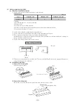
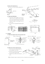
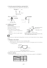
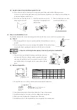
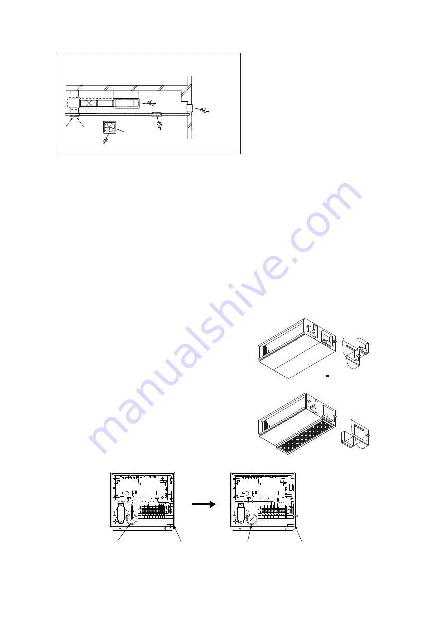
Bad example of duct work

For ventilation

Louver to
outdoor air

Before shipment from the 
plant, arrangements are made 
to enable maintenance from 
the sides of the unit.

Outlet of control wiring

Outlet of crossover wiring

Outlet of crossover wiring

Outlet of control wiring

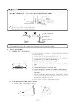
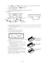
7) If a duct is not provided at the suction side but it is substituted with the space over the ceiling, humidity in the space will

increase by the influence of capacity of ventilation fan, strength of wind blowing against the out door air louver, weather

(rainy day) and others.

a) Moisture in air is likely to condense over the external plates of the unit and to drip on the ceiling.

Unit should be operated under the conditions as listed in the above table and within the limitation of wind volume.

When the building is a concrete structure, especially immediately after the construction, humidity tends to rise even

if the space over the ceiling is not substituted in place of a duct.

In such occasion, it is necessary to insulate the entire unit with glass wool (25mm). (Use a wire net or equivalent to

hold the glass wool in place.)

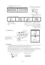
b) It may run out the allowable limit of unit operation (Example: When outdoor air temperature is 35˚C DB, suction air

temperature is 27˚C WB) and it could result in such troubles as compressor overload, etc..

c) There is a possibillty that the blow air volume may exceed the allowable range of operation due to the capacity of

ventilation fan or strength of wind blowing against external air louver so that drainage from be heat exchanger may

fail to reach the drain pan but leak outside (e. g. drip on to the ceiling) with consequential water leakage in the room.

(f)

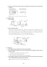
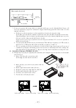
Control box (Only case of FDURA401, 501, 601)

During bottom side suction, the orientation of the control box can be changed to allow the control box to be maintained

from the inlet port.

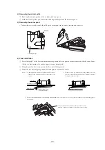
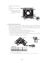
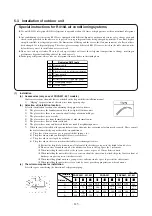
1) Remove the bottom plate (on the inlet port side),

and all wiring connectors from the control box.

2) Remove the three screws that fasten the cabinet inside the

control box.

3) Pull the control box toward the outside of the unit.

4) Change the ejection of the wiring inside the control box.

5) Fit the control box from the inside of the unit.

6) Fit the three screws that fasten the cabinet.

7) Correctly connect all wiring connectors.

Summary of Contents for FDENA301HEN

Page 1: ...models CEILING RECESSED TYPE CEILING SUSPENSION TYPE WALL MOUNTED TYPE CEILING MOUNTED DUCT TYPE FDTVA151HEN 201HEN 251HEN FDTA301HEN 301HES 401HEN 401HES 501HES 601HES FDENVA151HEN 201HEN 251HEN FDENA301HEN 301HES 401HEN 401HES 501HES 601HES FDKNVA151HEN 201HEN 251HEN FDKNA301HEN 301HES FDURVA201HEN 251HEN FDURA301HEN 301HES 401HEN 401HES 501HES 601HES ...

Page 2: ... 2 8 Characteristics of fan 59 2 9 Noise level 60 3 ELECTRICAL DATA 64 3 1 Electrical wiring 64 4 OUTLINE OF OPERATION CONTROL BY MICROCOMPUTER 75 5 APPLICATION DATA 94 5 1 Installation of indoor unit 95 5 2 Installation of remote controller 114 5 3 Installation of outdoor unit 115 6 MAINTENANCE DATA 128 6 1 Servicing 128 6 2 Trouble shooting for refrigerant circuit 129 6 3 Diagnosing of microcomp...

Page 3: ... between the outdoor and indoor unit One cabtyre cable with 3 wires encased in one sheath is enough for conducting the wiring work between the outdoor unit and the indoor unit This contributes to simpler wiring work in the field 5 All air supply ports have auto swing louvers Only case of FDT FDEN and FDKN models The indoor fan motor has three speeds of high medium and low 6 All models have service...

Page 4: ...ase heater Operation control Wired remote control switch Operation switch Optional RC E1 Indoor unit side Room temperature control Thermostat by electronics Safety equipment Internal thermostat for fan motor Internal thermostat for fan motor Frost protection thermostat Abnormal discharge temperature protection Installation data mm Liquid line φ6 35 1 4 Gas line φ12 7 1 2 Refrigerant piping size in...

Page 5: ...ssor Electric heater W 20 Crank case heater Operation control Wired remote control switch Operation switch Optional RC E1 Indoor unit side Room temperature control Thermostat by electronics Safety equipment Internal thermostat for fan motor Internal thermostat for fan motor Frost protection thermostat Abnormal discharge temperature protection Installation data mm Liquid line φ6 35 1 4 Gas line φ12...

Page 6: ...ectric heater W 20 Crank case heater Operation control Wired remote control switch Operation switch Optional RC E1 Indoor unit side Room temperature control Thermostat by electronics Safety equipment Internal thermostat for fan motor Internal thermostat for fan motor Frost protection thermostat Abnormal discharge temperature protection Installation data mm Liquid line φ6 35 1 4 Gas line φ15 88 5 8...

Page 7: ...on absorber Rubber sleeve for fan motor Rubber mount for compressor Electric heater W 33 Crank case heater Operation control Wired remote control switch Operation switch Optional RC E1 Indoor unit side Room temperature control Thermostat by electronics Safety equipment Internal thermostat for fan motor Internal thermostat for fan motor Frost protection thermostat Abnormal discharge temperature pro...

Page 8: ...n absorber Rubber sleeve for fan motor Rubber mount for compressor Electric heater W 33 Crank case heater Operation control Wired remote control switch Operation switch Optional RC E1 Indoor unit side Room temperature control Thermostat by electronics Safety equipment Internal thermostat for fan motor Internal thermostat for fan motor Frost protection thermostat Abnormal discharge temperature prot...

Page 9: ...ion absorber Rubber sleeve for fan motor Rubber mount for compressor Electric heater W 33 Crank case heater Operation control Wired remote control switch Operation switch Optional RC E1 Indoor unit side Room temperature control Thermostat by electronics Safety equipment Internal thermostat for fan motor Internal thermostat for fan motor Frost protection thermostat Abnormal discharge temperature pr...

Page 10: ...n absorber Rubber sleeve for fan motor Rubber mount for compressor Electric heater W 33 Crank case heater Operation control Wired remote control switch Operation switch Optional RC E1 Indoor unit side Room temperature control Thermostat by electronics Safety equipment Internal thermostat for fan motor Internal thermostat for fan motor Frost protection thermostat Abnormal discharge temperature prot...

Page 11: ...tion absorber Rubber sleeve for fan motor Rubber mount for compressor Electric heater W 40 Crank case heater Operation control Wired remote control switch Operation switch Optional RC E1 Indoor unit side Room temperature control Thermostat by electronics Safety equipment Internal thermostat for fan motor Internal thermostat for fan motor Frost protection thermostat Abnormal discharge temperature p...

Page 12: ...tion absorber Rubber sleeve for fan motor Rubber mount for compressor Electric heater W 40 Crank case heater Operation control Wired remote control switch Operation switch Optional RC E1 Indoor unit side Room temperature control Thermostat by electronics Safety equipment Internal thermostat for fan motor Internal thermostat for fan motor Frost protection thermostat Abnormal discharge temperature p...

Page 13: ...less remote control switch Optional RCN E1 Operation switch Wired remote control switch Optional RC E1 Indoor unit side Room temperature control Thermostat by electronics Safety equipment Internal thermostat for fan motor Internal thermostat for fan motor Frost protection thermostat Abnormal discharge temperature protection Installation data mm Liquid line φ6 35 1 4 Gas line φ12 7 1 2 Refrigerant ...

Page 14: ...on control Wireless remote control switch Optional RCN E1 Operation switch Wired remote control switch Optional RC E1 Indoor unit side Room temperature control Thermostat by electronics Safety equipment Internal thermostat for fan motor Internal thermostat for fan motor Frost protection thermostat Abnormal discharge temperature protection Installation data mm Liquid line φ6 35 1 4 Gas line φ12 7 1...

Page 15: ... control Wireless remote control switch Optional RCN E1 Operation switch Wired remote control switch Optional RC E1 Indoor unit side Room temperature control Thermostat by electronics Safety equipment Internal thermostat for fan motor Internal thermostat for fan motor Frost protection thermostat Abnormal discharge temperature protection Installation data mm Liquid line φ6 35 1 4 Gas line φ15 88 5 ...

Page 16: ...r fan motor Rubber mount for compressor Electric heater W 33 Crank case heater Operation control Wireless remote control switch Optional RCN E1 Operation switch Wired remote control switch Optional RC E1 Indoor unit side Room temperature control Thermostat by electronics Safety equipment Internal thermostat for fan motor Internal thermostat for fan motor Frost protection thermostat Abnormal discha...

Page 17: ...or fan motor Rubber mount for compressor Electric heater W 33 Crank case heater Operation control Wireless remote control switch Optional RCN E1 Operation switch Wired remote control switch Optional RC E1 Indoor unit side Room temperature control Thermostat by electronics Safety equipment Internal thermostat for fan motor Internal thermostat for fan motor Frost protection thermostat Abnormal disch...

Page 18: ... for fan motor Rubber mount for compressor Electric heater W 33 Crank case heater Operation control Wireless remote control switch Optional RCN E1 Operation switch Wired remote control switch Optional RC E1 Indoor unit side Room temperature control Thermostat by electronics Safety equipment Internal thermostat for fan motor Internal thermostat for fan motor Frost protection thermostat Abnormal dis...

Page 19: ...for fan motor Rubber mount for compressor Electric heater W 33 Crank case heater Operation control Wireless remote control switch Optional RCN E1 Operation switch Wired remote control switch Optional RC E1 Indoor unit side Room temperature control Thermostat by electronics Safety equipment Internal thermostat for fan motor Internal thermostat for fan motor Frost protection thermostat Abnormal disc...

Page 20: ... for fan motor Rubber mount for compressor Electric heater W 40 Crank case heater Operation control Wireless remote control switch Optional RCN E1 Operation switch Wired remote control switch Optional RC E1 Indoor unit side Room temperature control Thermostat by electronics Safety equipment Internal thermostat for fan motor Internal thermostat for fan motor Frost protection thermostat Abnormal dis...

Page 21: ... for fan motor Rubber mount for compressor Electric heater W 40 Crank case heater Operation control Wireless remote control switch Optional RCN E1 Operation switch Wired remote control switch Optional RC E1 Indoor unit side Room temperature control Thermostat by electronics Safety equipment Internal thermostat for fan motor Internal thermostat for fan motor Frost protection thermostat Abnormal dis...

Page 22: ... control Wireless remote control switch Optional RCN E1 Operation switch Wired remote control switch Optional RC E1 Indoor unit side Room temperature control Thermostat by electronics Safety equipment Internal thermostat for fan motor Frost protection thermostat Installation data mm Liquid line φ6 35 1 4 Gas line φ12 7 1 2 Refrigerant piping size in Connecting method Flare piping Drain hose Connec...

Page 23: ...er Operation control Wireless remote control switch Optional RCN E1 Operation switch Wired remote control switch Optional RC E1 Indoor unit side Room temperature control Thermostat by electronics Safety equipment Internal thermostat for fan motor Frost protection thermostat Installation data mm Liquid line φ6 35 1 4 Gas line φ12 7 1 2 Refrigerant piping size in Connecting method Flare piping Drain...

Page 24: ...r Operation control Wireless remote control switch Optional RCN E1 Operation switch Wired remote control switch Optional RC E1 Indoor unit side Room temperature control Thermostat by electronics Safety equipment Internal thermostat for fan motor Frost protection thermostat Installation data mm Liquid line φ6 35 1 4 Gas line φ15 88 5 8 Refrigerant piping size in Connecting method Flare piping Drain...

Page 25: ...bber sleeve for fan motor Rubber mount for compressor Electric heater W 33 Crank case heater Operation control Wireless remote control switch Optional RCN E1 Operation switch Wired remote control switch Optional RC E1 Indoor unit side Room temperature control Thermostat by electronics Safety equipment Internal thermostat for fan motor Frost protection thermostat Installation data mm Liquid line φ9...

Page 26: ... motor Rubber mount for compressor Electric heater W 33 Crank case heater Operation control Wireless remote control switch Optional RCN E1 Operation switch Wired remote control switch Optional RC E1 Indoor unit side Room temperature control Thermostat by electronics Safety equipment Internal thermostat for fan motor Frost protection thermostat Installation data mm Liquid line φ9 52 3 8 Gas line φ1...

Page 27: ...ne net 1 washable Shock vibration absorber Rubber sleeve for fan motor Rubber mount for compressor Electric heater W 20 Crank case heater Operation control Wired remote control switch Operation switch Optional RC E1 Indoor unit side Room temperature control Thermostat by electronics Safety equipment Internal thermostat for fan motor Internal thermostat for fan motor Frost protection thermostat Abn...

Page 28: ...er Rubber sleeve for fan motor Rubber mount for compressor Electric heater W 20 Crank case heater Operation control Wired remote control switch Operation switch Optional RC E1 Indoor unit side Room temperature control Thermostat by electronics Safety equipment Internal thermostat for fan motor Internal thermostat for fan motor Frost protection thermostat Abnormal discharge temperature protection I...

Page 29: ...sure Pa Standard 50 Max 130 Fresh air intake Air filter Q ty Polypropylene net 1 washable Shock vibration absorber Rubber sleeve for fan motor Rubber mount for compressor Electric heater W 33 Crank case heater Operation control Wired remote control switch Operation switch Optional RC E1 Indoor unit side Room temperature control Thermostat by electronics Safety equipment Internal thermostat for fan...

Page 30: ...r intake Air filter Q ty Polypropylene net 1 washable Shock vibration absorber Rubber sleeve for fan motor Rubber mount for compressor Electric heater W 33 Crank case heater Operation control Wired remote control switch Operation switch Optional RC E1 Indoor unit side Room temperature control Thermostat by electronics Safety equipment Internal thermostat for fan motor Internal thermostat for fan m...

Page 31: ...air intake Air filter Q ty Polypropylene net 1 washable Shock vibration absorber Rubber sleeve for fan motor Rubber mount for compressor Electric heater W 33 Crank case heater Operation control Wired remote control switch Operation switch Optional RC E1 Indoor unit side Room temperature control Thermostat by electronics Safety equipment Internal thermostat for fan motor Internal thermostat for fan...

Page 32: ...ir intake Air filter Q ty Polypropylene net 1 washable Shock vibration absorber Rubber sleeve for fan motor Rubber mount for compressor Electric heater W 33 Crank case heater Operation control Wired remote control switch Operation switch Optional RC E1 Indoor unit side Room temperature control Thermostat by electronics Safety equipment Internal thermostat for fan motor Internal thermostat for fan ...

Page 33: ... air intake Air filter Q ty Polypropylene net 1 washable Shock vibration absorber Rubber sleeve for fan motor Rubber mount for compressor Electric heater W 40 Crank case heater Operation control Wired remote control switch Operation switch Optional RC E1 Indoor unit side Room temperature control Thermostat by electronics Safety equipment Internal thermostat for fan motor Internal thermostat for fa...

Page 34: ... air intake Air filter Q ty Polypropylene net 1 washable Shock vibration absorber Rubber sleeve for fan motor Rubber mount for compressor Electric heater W 40 Crank case heater Operation control Wired remote control switch Operation switch Optional RC E1 Indoor unit side Room temperature control Thermostat by electronics Safety equipment Internal thermostat for fan motor Internal thermostat for fa...

Page 35: ...rant line one way length Vertical height difference between outdoor unit and indoor unit Power source voltage Voltage at starting Cycle Time Stop Time Dew point temperature 28 C or less relative humidity 80 or less Refer to the selection chart Max 40m Max 50m 6 minutes or more from ON to ON or from OFF to OFF 3 minutes or more Min 85 of rating Rating 10 Compressor ON OFF Frequency Max 30m Outdoor ...

Page 36: ... ø4 860 890 Ceiling hole size 780 Suspension bolts pitch 675 Suspension bolts pitch Control box Fresh air opening for ducting Exhaust air opening for ducting Control box Gas piping ø6 35 1 4 Liquid piping or more Lug for suspension bolts Space for installation and service Obstacle Holes for tapping screws Holes for tapping screws Holes Holes Suspension bolts B D C Drain Connectable with VP25 1000 ...

Page 37: ...140 52 ø15 88 5 8 A 4 ø4 4 ø4 860 890 Ceiling hole size 780 Suspension bolts pitch 675 Suspension bolts pitch Control box Fresh air opening for ducting Exhaust air opening for ducting Control box Gas piping ø9 52 3 8 Liquid piping or more Lug for suspension bolts Space for installation and service Obstacle Holes for tapping screws Holes for tapping screws Holes Holes Suspension bolts B D C Drain C...

Page 38: ...ling hole size 780 Suspension bolts pitch 675 Suspension bolts pitch A 35 295 187 137 840 212 95 45 or more 950 630 Air inlet grille Gas piping ø15 88 5 8 Air outlet Hole Hole 80 77 100 140 100 147 140 60 148 140 160 68 55 25 4 ø4 Holes for tapping screws 4 ø4 Holes for tapping screws Space for installation and service Drain Connectable with VP25 Suspension bolts VIEW C VIEW D Fresh air opening fo...

Page 39: ...on bolts 780 Suspension bolts pitch 675 Suspension bolts pitch B A Air outlet Air inlet grille Drain hose Accessories Local setting Decorative Panel 4 ø4 4 ø4 Holes for tapping screws Holes for tapping screws Drain Connectable with VP25 Suspension bolts Hole for wiring VIEW A VIEW B VIEW D VIEW C Space for installation and service Fresh air opening for ducting Exhaust air opening for ducting D C L...

Page 40: ...sble to take incline of 10mm Indication board 100 300 150 5 75 110 135 308 40 40 1240 1320 173 210 5 215 24 24 690 195 235 271 53 109 52 68 410 135 10 53 145 76 1272 Suspension bolts pitch 290 Suspension bolts pitch Air inlrt grille Indication board 251 ø6 35 1 4 301 ø9 52 3 8 ø15 88 5 8 Holes for suspension bolts M8 to M10 4pcs Not included Liquid piping Gas piping Liquid piping Gas piping Space ...

Page 41: ...o take incline of 10mm Indication board Models FDENA401 501 601 Unit mm Service space 4 12 18 long hole Service space Space for installation and service or more or more or more or more 40 15 100 50 Installation position diagram and installation space from the front 67 60 63 5 387 5 457 5 515 53 5 44 5 15 284 2 5 3 8 5 40 100 73 5 693 5073 5 182 5 450 207 5 50 50 220 5 47 5 44 5 25 44 60 3 240 44 6...

Page 42: ...et for piping Indication board Outlet for piping Outlet for electric wiring 4 12 18 long hole Mounting plate Model FDKNA301 Unit mm 45 35 75 51 450 4 5 5 15 long hole 8 12 18 long hole 450 690 45 75 51 245 100 1047 54 50 465 515 600 65 72 9 282 5 6 5 Service space 40 37 60 209 245 50 50 50 50 220 54 1155 298 1145 196 9 55 3 51 Service space Service space Drain hose VP16 Liquid piping Gas piping ø9...

Page 43: ... 240 80 475 25 295 245 35 70 886 Suspension bolts pitch Low of suspension lug Suspension bolts M10 4pcs 145 30 650 45 30 45 560 18 Suspension bolts pitch 850 Dimension for duct Air outlet duct Liquid piping ø6 35 1 4 Gas piping 201 ø12 7 1 2 251 ø15 88 5 8 Drain Connectable with VP25 Drain Natural drainage VP20 Unit mm 850 600 1200 100 635 Inspection hole d Ceiling mounted duct type FDUR Models FD...

Page 44: ...n for duct 18 25 525 480 420 240 80 475 25 295 245 35 70 886 Suspension bolts pitch Low of suspension lug Suspension bolts M10 4pcs 145 30 650 45 30 45 560 18 Suspension bolts pitch 850 Dimension for duct Air outlet duct Liquid piping ø9 52 3 8 Gas piping ø15 88 5 8 Drain Connectable with VP25 Drain Natural drainage VP20 Unit mm 850 600 1200 100 635 Inspection hole Model FDURA301 ...

Page 45: ... M10 4pcs 173 30 650 45 30 45 560 18 Suspension bolts pitch 1370 Dimension for duct Air outlet duct Liquid piping ø9 52 3 8 Gas piping ø15 88 8 5 Drain Connectable with VP25 Drain Natural drainage VP20 1370 600 1720 100 635 Inspection hole 600 Max Drain up Air outlet Ceiling surface Drain hose Accessories Local Locality Models FDURA401 501 601 Space for installation and service Unit mm ...

Page 46: ...arts intended for screw holes and then fix it with screws This side is not grounded Earth Remote control switch Remote control cord Shielded wire Precation in Extending the Remote control cord The cord should be a shielded wire For all types 0 3mm2 3 cores Note 1 Use cables up to 0 5mm2 maximum for those laid inside the remote control unit casing and connect to a different size cable at a vicinity...

Page 47: ... 45 b Wireless remote controller Unit mm MODE TEMP ON OFF AUTO COOL DRY FAN HEAT FILTER C AM PM ON AM PM OFF FAN HI LO 60 20 5 161 5 ...

Page 48: ...et must be oriented at right angle against the wind direction 4 Secure a space of 1 m or more above the unit 5 Barrier standing in front of the blow outlet must be lower than the height of unit Unit mm 3 Outdoor unit Models FDCVA151HEN 201HEN Liquid piping ø6 35 1 4 Flare connecting Gas piping ø12 7 1 2 Flare connecting Piping wiring outlet L2 L1 L3 Terminal block Holes for drain ø20 5 pcs Holes f...

Page 49: ...e blow outlet must be oriented at right angle against the wind direction 4 Secure a space of 1 m or more above the unit 5 Barrier standing in front of the blow outlet must be lower than the height of unit Unit mm Model FDCVA251HEN Liquid piping ø6 35 1 4 Flare connecting Gas piping ø15 88 5 8 Flare connecting Piping wiring outlet L2 L1 L3 Terminal block Holes for drain ø20 5 pcs Holes for anchor b...

Page 50: ...t must be lower than the height of unit Unit mm Models FDCA301HEN 301HES L4 L3 L2 L1 50 110 195 880 10 40 38 53 95 50 50 110 195 50 70 460 482 15 50 27 50 15 50 845 55 150 40 150 580 150 40 20 380 20 15 103 50 50 310 40 55 340 47 222 15 60 Maintenance space Air inlet Air inlet Air outlet Terminal block Liquid piping ø9 52 3 8 Flare connecting Liquid piping ø9 52 3 8 Flare connecting Gas piping ø15...

Page 51: ... must be lower than the height of unit Unit mm Models FDCA401HEN 401HES VIEW A Maintenance space Liquid piping ø9 52 3 8 Flare connecting Gas piping ø15 88 5 8 Flare connecting Holes for anchor bolt M10 4 pcs Holes for drain ø20 3 pcs Opening for electric wring Opening for electric wring Opening for piping and electric wring Opening for electric wiring Opening for piping and electric wring Opening...

Page 52: ...utlet must be lower than the height of unit Unit mm Model FDCA501HES VIEW A A Holes for drain ø20 3 pcs L4 L3 L2 L1 60 580 38 50 110 10 40 48 53 99 40 410 15 103 60 50 50 195 50 70 50 15 50 27 50 15 388 262 15 40 55 55 150 1300 40 110 195 628 650 970 200 60 190 20 20 370 Air inlet Air inlet Air outlet Terminal block Maintenance space Liquid piping ø9 52 3 8 Flare connecting Liquid piping ø9 52 3 8...

Page 53: ...tlet must be lower than the height of unit Unit mm Model FDCA601HES VIEW A L4 L3 L2 L1 60 580 38 50 110 10 46 50 48 100 40 410 15 103 60 50 50 195 50 70 50 15 50 27 50 15 388 262 15 40 55 55 150 1300 40 110 195 589 648 970 200 60 190 20 20 370 A Air inlet Air inlet Air outlet Terminal block Maintenance space Liquid piping ø9 52 3 8 Flare connecting Liquid piping ø9 52 3 8 Flare connecting Gas pipi...

Page 54: ...or 4 way valve Service valve Service valve High pressure switch Liquid side Gas side 63H1 Compressor Control box Electronic expansion valve Receiver 4 way valve Service valve Service valve Liquid side Heating Receiver Cooling Gas side Compressor Electronic expansion valve Models FDCA401HEN 401HES ...

Page 55: ...al louver Light gray Light gray Air inlet grille Noble white Pearl white Ivory white Front panel Ivory white Flap 2 5 Exterior appearance 1 Indoor unit a Ceiling recessed type FDT b Ceiling suspension type FDEN c Wall mounted type FDKN Models FDKNA151 201 251 Model FDKNA301 Ivory white Base d Ceiling mounted duct type FDUR Zinc steel plate ...

Page 56: ... 54 Sutakko white Polar white Polar white Polar white 2 Outdoor unit Models FDCVA151HEN 201HEN 251HEN Models FDCA301HEN 301HES Models FDCA401HEN 401HES Models FDCA501HES 601HES ...

Page 57: ...mpressor Check joint Check joint Note 1 A FDE type strainer only should be used for the indoor unit Cooling cycle Heating cycle Thermistor ThI R2 Thermistor ThI R1 Thermistor ThO D Thermistor ThO A Sub Cooling Coil Service valve Flare connecting Service valve Flare connecting Thermistor ThO R2 High pressure switch 63H1 Thermistor ThO R1 Electronic expansion valve EEV Thermistor ThI A Heat exchange...

Page 58: ...mistor for frost prevention Thermistor for detecting dis charge pipe temp High pressure switch for protection OFF 63 C ON 56 C Equipped unit ThI R Tho D 63H1 Indoor unit Outdoor unit Outdoor unit OFF 1 0 C ON 10 C OFF 105 C ON 80 C 301 401 501 601 models OFF 4 15MPa ON 3 15MPa 151 201 251 models OFF 121 C ON 80 C ...

Page 59: ...n on specification Correction factors as follows 1 Coefficient of cooling and heating capacity in relation to temperatures Indoor air W B temperature CW B ISO T1 Standard condition Outdoor air D B temperature CD B Cooling operation Indoor air D B temperature CD B Heating operation Coefficient of cooling and heating capacity in relation to temperatures ISO T1 Standard condition Outdoor air W B temp...

Page 60: ...t in cooling operation and when the outdoor unit is located at a higher height than the indoor unit in heating operation the following values should be subtracted from the values in the above table Height difference between the indoor unit and outdoor unit in the vertical height difference 5m 10m 15m 20m 25m 30m Adjustment coefficient 0 01 0 02 0 03 0 04 0 05 0 06 Piping length limitations Item Mo...

Page 61: ...d a r d L o w e r Lower limit 0 20 10 40 30 60 70 80 90 100 110 120 13 12 14 15 16 17 18 19 Upper limit 50 Standard pressure Standard air flow Air flow m3 min Static pressure Pa Highspeed Upper Highspeed Upper limit limit Highspeed Upper limit High speed Lower High speed Lower limit limit High speed Lower limit High speed High High speed High High speed High H i g h s p e e d L o w H i g h s p e e...

Page 62: ...igh speed Lower limit High speed Lower limit High speed High High speed High H i g h s p e e d L o w S t a n d a r d L o w S t a n d a r d L o w H i g h s p e e d H i g h High speed Upper limit High speed Lower limit High speed High H i g h s p e e d L o w S t a n d a r d L o w H i g h s p e e d H i g h Standard Upper limit Standard Upper limit Standard Upper limit 1 5m Mike center low points Mode...

Page 63: ...0 20 30 10 20 30 N50 N40 N30 N20 60 60 N10 Souud Pressure Level standard 0 0002µ bar Mid Octave Band Frequency Hz Souud Pressure Level standard 0 0002µ bar Mid Octave Band Frequency Hz N30 N40 N20 N50 N60 N70 63 125 250 500 1000 2000 4000 8000 20 30 40 50 60 70 20 30 40 50 60 70 Souud Pressure Level standard 0 0002µ bar Mid Octave Band Frequency Hz N30 N40 N20 N50 N60 N70 63 125 250 500 1000 2000 ...

Page 64: ...02µ bar Mid Octave Band Frequency Hz N30 N40 N20 N50 N60 N70 63 125 250 500 1000 2000 4000 8000 20 30 40 50 60 70 20 30 40 50 60 70 Souud Pressure Level standard 0 0002µ bar Mid Octave Band Frequency Hz N30 N40 N20 N50 N60 N70 63 125 250 500 1000 2000 4000 8000 20 30 40 50 60 70 20 30 40 50 60 70 Model FDKNA301 Noise level 49 dB A at HIGH 46 dB A at MEDIUM 43 dB A at LOW Souud Pressure Level stand...

Page 65: ...ard 0 0002µ bar Mid Octave Band Frequency Hz N30 N40 N20 N50 N60 N70 63 125 250 500 1000 2000 4000 8000 20 30 40 50 60 70 20 30 40 50 60 70 Souud Pressure Level standard 0 0002µ bar Mid Octave Band Frequency Hz N30 N40 N20 N50 N60 N70 63 125 250 500 1000 2000 4000 8000 20 30 40 50 60 70 20 30 40 50 60 70 Models FDCA401HEN 401HES Noise level 54 dB A Model FDCA501HES Noise level 56 dB A Model FDCA60...

Page 66: ...output DC12V output XR5 X1 2 3 6 X4 TB CnB Z mark Remote operation input volt free contact Auxiliary relay For FM Auxiliary relay For DM Terminal block mark Connector Closed end connector Mark Parts name Mark Parts name Mark Parts name Meaning of marks Color marks BK BL BR OR P RD WH Y Y GN Black Blue Brown Orange Pink Red White Yellow Yellow Green Mark Color SW5 SW9 SW2 LED 2 LED 1 Power board Pr...

Page 67: ...ED1 LED2 XR1 XR2 XR3 XR4 XR5 Emergency operation Transformer Fuse Indication lamp Red Indication lamp Green Operation output DC12V output Heating output DC12V output Thermo ON output DC12V output Inspection output DC12V output Remote operation input volt free contact X4 TB CnB Z mark Auxiliary relay For DM Terminal block mark Connector Closed end connector Mark Parts name Mark Parts name Mark Part...

Page 68: ... Green Operation output DC12V output Heating output DC12V output Thermo ON output DC12V output Inspection output DC12V output Remote operation input volt free contact Auxiliary relay For FM Terminal block mark Connector mark LED 1 LED 2 LED 3 SW1 SW2 Closed end connector Indication lamp Green Operation Indication lamp Yellow Timer Check 7 segement indicator For check Switch For setting Backup swit...

Page 69: ...mp Green Run Indication lamp Yellow Inspection alert Transformer Fuse Indication lamp Red Indication lamp Green Operation output DC12V output Heating output DC12V output XR3 XR4 XR5 TB CnA Z AMP Thermo ON output DC12V output Inspection output DC12V output Remote operation input volt free contact Terminal block mark Connector Wirelss receiver Mark Parts name Mark Parts name Mark Parts name Meaning ...

Page 70: ...low Timer Inspction alert Indication lamp Green Run Fuse Indication lamp Red Indication lamp Green Operation output DC12V output XR2 XR3 XR4 XR5 TB CnA Z AMP Heating output DC12V output Thermo ON output DC12V output Inspection output DC12V output Remote operation input volt free contact Terminal block mark Connector Wirelss receiver Mark Parts name Mark Parts name Mark Parts name Meaning of marks ...

Page 71: ...p Green Operation output DC12V output Heating output DC12V output XR3 XR4 XR5 X1 2 3 6 X4 TB CnA Z mark Thermo ON output DC12V output Inspection output DC12V output Remote operation input volt free contact Auxiliary relay For FM Auxiliary relay For DM Terminal block mark Connector Closed end connector Mark Parts name Mark Parts name Mark Parts name Meaning of marks 1 2 3 4 5 6 1 2 3 1 3 1 3 5 7 9 ...

Page 72: ...ellow Green Yellow Parts name Mark Meaning of marks Tho A Tho D Tho R TB Terminal block mark SW5 1 Defrost control switch SW5 2 Snow prevented fan control switch SW5 4 Operate test run switch Cooling Heating SW9 Pump down switch SM Stepping motor for EEV Thermistor discharge temp Tho IPM Thermistor Power transistor temp Thermistor outdoor H EX temp Thermistor outdoor air temp Parts name Mark 20S 4...

Page 73: ...Mark Color mark TB Y GN TB BL WH Y GN Color BK BL BR OR P RD Black Blue Brown Orange Pink Red BK WH Mark Color WH White BK WH Black White BL WH Blue White RD Y Red Yellow Y Y GN Yellow Green Yellow Parts name Mark Meaning of marks L N RD Cc Capacitor for CM Tho A Tho D Tho R1 2 TB Terminal block mark SW5 1 Defrost control switch SW5 2 Snow prevented fan control switch SW5 4 Operate test run switch...

Page 74: ... P P BR BR BL WH WH BK WH RD Y RD WH BL RD WH BL CNE Checker CNQ Test Indication lamp Red Mark Color mark TB Y GN L2 L3 TB BL WH Y GN Color BK BL BR OR P RD Black Blue Brown Orange Pink Red BK WH N BK WH Mark Color WH White BK WH Black White BL WH Blue White RD Y Red Yellow Y Y GN Yellow Green Yellow CT2 Parts name Mark Meaning of marks Tho A Tho D Tho R1 2 Thermistor outdoor H Ex temp TB Terminal...

Page 75: ...ation lamp Red Mark Color mark TB Y GN TB BL WH Y GN Color BK BL BR OR P RD Black Blue Brown Orange Pink Red GR Gray BK WH Mark Color WH White BK WH Black White BL WH Blue White RD Y Red Yellow Y Y GN Yellow Green Yellow Parts name Mark Meaning of marks L N RD Cc Capacitor for CM Tho A Tho D Tho R1 2 TB Terminal block mark SW5 1 Defrost control switch SW5 2 Snow prevented fan control switch SW5 4 ...

Page 76: ... Y RD WH BL RD WH BL CNE Checker CNQ Test Indication lamp Red Mark TB Y GN L2 L3 TB BL WH Y GN Color BK BL BR OR P RD Black Blue Brown Orange Pink Red GR Gray BK WH N BK WH Mark Color WH White BK WH Black White BL WH Blue White RD Y Red Yellow Y Y GN Yellow Green Yellow CT2 Parts name Mark Tho A Tho D Tho R1 2 Thermistor outdoor H Ex temp TB Terminal block mark SW5 1 Defrost control switch SW5 2 S...

Page 77: ...lashing in red FAN SPEED switch This switch is used to set the airflow volume SET switch This switch is used to apply the timer operation setting This switch is also used to make silent mode operation settings RESET switch Press this switch while making settings to go back to the previous operation This switch is also used to reset the FILTER CLEANING message display Press this switch after cleani...

Page 78: ...ir flow direction button Used to start or stop the swing louver Signal sender Signals are sent to the air conditioner from here Filter reset indicator The FILTER mark is indicated when the FILTER RESET button is pressed Temperature indicator Set temperature is indicated Timer OFF time Indicated the timer OFF time When the timer mode is CONT or OFF there is no indication ON OFF button When the butt...

Page 79: ... on the remote control device the selection of cooling or heating can be made automatically depending on the room temperature and the temperature of indoor heat exchanger When the switching between the cooling and the heating is made within 3 minutes the compressor will not operate for 3 minutes This will make much easier the switching of cooling heating at the change of season and can be adapted ...

Page 80: ...t Pattern of operation Operation block Thermal drying starting for 8 or 16 minutes after operation started A 16 minutes The air flow is set at 1 speed lower than the set air flow 8 minutes Continuous cooling operation FMI Lo B 8 minutes CM FM0 FMI C 8 minutes CM FM0 FMI 8 minutes CM FM0 FMI D 8 minutes All stoppage e Timer Operation 1 Simple Timer This sets the amount of time from the current time...

Page 81: ...e 30 C or above or 7 minutes passes Heat exchanger temperature 30 C or above or 7 minutes passes Compressor ON Defrosting ends Thermostat ON Thermostat OFF Defrosting starts Compressor OFF Notes 1 If J2 starts it changes from OFF to Lo for 5 minutes Notes 2 During Hot Start the compressor is operating and the indoor fan is not operating at the set air flow Heating preparation is displayed g FM con...

Page 82: ...R model 1 Louver Control a While the air conditioner is operating press the LOUVER switch AUTO is displayed for 3 seconds and the swing louvers move up and down continuously b When fixing the position of the swing louvers press the LOUVER switch once while the swing louvers are moving 4 stop positions are displayed in sequence at 1 second intervals When the display comes to the position where you ...

Page 83: ...n if the thermostat goes OFF the louver position is set in the horizontal position Note 1 The compressor stops when protection control starts n Heating overload porotection If an overload condition is sensed continuously for 2 seconds by the indoor heat exchanger temperature during heating sensed by Thi R1 or R2 the compressor is stopped After a 3 minute delay the compressor is restarted If the ov...

Page 84: ... the group controller and use a jumper wire among each of the rooms r External control remote display control of input signal 1 External control remote display output Following output connectors CnT are provided on the control circuit board of indoor unit Operation output Power to engage DC 12V relay provided by the customer is outputted during operation Heating output Power to engage DC 12V relay...

Page 85: ...nit is turned on at the field Input signal to CnT becomes Valid at OFF ON only and the motion of air conditioner ON OFF is inverted CnT Input Air Conditioner A Air Conditioner B OFF OFF ON ON ON ON ON ON ON OFF OFF OFF ON OFF OFF OFF OFF OFF ON ON ON ON ON OFF OFF OFF OFF CnT Input Air Conditioner A Air Conditioner B Note 1 The ON at the mark indicates ON using the remote control switch etc ...

Page 86: ...ensation using the remote control function settings Normally the remote control s state is recorded in memory and after recovery following a power failure operation is re started in accordance with the contents in memory However the auto swing stop position and the timer mode are cancelled However the weekly timer setting is reset with the Holiday setting set for all day Remote controller board pa...

Page 87: ...N conditions have been established 2 The bottom limit compressor speed is 30 rps and the upper limit is 64 rps If the compressor s speed is increased it is increased by 6 rps 30 seconds 3 This control is terminated 3 minutes after the compressor has started 2 Compressor protective start 2 If any of the following conditions is satisfied compressor start II is implemented a It has been 6 hours or lo...

Page 88: ...rotective start I Protective start II First time since the compressor was turned ON 2nd or subsequent time since the compressor was turned ON Less than 6 hours since the power was turned ON 6 hours or longer since the power was turned ON Less than 6 hours since stop 6 hours or longer since stop In accordance with the following conditions Protective start II Protective start I Protective start II P...

Page 89: ...th the outdoor heat exchanger temperature sensed by Tho R and the outdoor air temperature sensed by Tho A A Zone B Zone 22 25 Outdoor air temperature C Retain 1 Speed Lower limit 1st speed 29 48 Outdoor heat exchanger temperature C 1 Speed Upper limit 4th speed a After detecting the B zone temperature the outdoor fan tap speed is immediately raised to 4th speed and this speed is retained for 60 se...

Page 90: ...ed once every 10 minutes Hi tap Note 1 Values in show for the 301 601 models f Defrosting 1 Defrosting start conditions Defrosting operation starts when all the follow ing conditions are satisfied a If 45 minutes 35 1 of cumulative compres sor operating time have passed since defrost ing ended and cumulative compressor operat ing time of 30 minutes have passed since heat ing operation started Remo...

Page 91: ...c Other than items a and b the same as standard conditions 3 Defrosting end conditions If any of the following conditions is satisfied the defrosting end operation starts a If 10 minutes 1 have passed since defrosting started b If the temperature at the outdoor heat exchanger thermistor Tho R is 12ºC or higher in the case of models 151 251 or 14ºC or higher in the case of models 301 601 continuous...

Page 92: ...d is reduced to control high pressure in accordance with the indoor heat exchanger tem perature sensed by Thi R after the compressor starts Indoor heat exchanger temperature C Compressor speed rps 57 or more 52 or more 47 or more less than 88 88 to less than 108 108 or more Model Item FDCVA151 251 Retention Compressor stops Compressor operates 80 105 121 Discharge pipe temperature C 1 Compressor s...

Page 93: ...comes possible to reset the unit using the remote control unit vii Heating low outdoor temperature protection control FDCVA 151 251 models only If a temperature of 10ºC is sensed at the heat exchanger sensed by Tho R continuously for 1 minute during opera tion the upper limit of the compressor speed is changed to 100 rps OFF 7 Heat exchanger temperature C 10 ON h Inverter protection control FDCVA ...

Page 94: ...in 4 seconds after changing to compressor rotor position detection operation the rotor s position cannot be detected a second time the compressor is stopped After 3 minutes the compressor recovers automatically but if this condition recurs 4 times in a 15 minute period an abnormal stop E60 is performed m Insufficient refrigerant protection control FDCVA 151 251 models 1 minute after the compressor...

Page 95: ...apacity Mode Cooling operation Heating operation Cooling The initial setting temperature is 5ºC The temperature at the indoor unit s heat exchanger is displayed in the return air temperature display The initial set temperature for heating preparation is 30ºC and the return air temperature is displayed in the return air temperature display Note 1 Items in show in the case of models 301 601 2 Test o...

Page 96: ...not get off their support and then fix the service panel securely Improper installation can cause heat generation and a resultant fire Please prevent any substance other than the specified refrigerant R410A such as air from entering the refrigerant cycle in installing or moving the air conditioning system Contamination by air or a foreign substance can cause an abnormal pressure build up inside th...

Page 97: ... further covered with insulation materials of 10 20 mm thick 3 Consider the supporting strength of the location If the strength is not sufficient to sustain the unit weight use reinforcing materials b Installation space for unit a When a sufficient interval cannot be secured between the unit and a wall or another unit shut up diffusers on that side to block winds and make sure that no short circui...

Page 98: ...h water filled inside to check the level of the unit A tolerable height difference at an end of the unit is within 3 mm When embedded into ceiling 1 Determine the positions of hanging bolts 675 780 The pitch center of a hanging bolt must accord with the center of the unit 2 Use four suspension bolts each fastened in such a manner that it can withstand pull force of 50 kgf 3 In cutting an opening o...

Page 99: ...st has to be performed even if the unit is installed in the season when the unit is used for healting 3 In a new house perform the test before the ceiling is fitted Using a water pump pour about 1000 cc of water to the drain pan through the blowing outlet Check the transparent drain out section of the drain hose for normal flow of drainage While observing the noise from the drain motor test drain ...

Page 100: ...lation height Remove the level gauge before installing the unit The unit s installation height can be minutely ad justed by means of the corner openings after the panel is installed For details see 6 Installing the Panel Note 1 If the installation level of the air conditioner unit and ceiling material exceed the proper range it will cause an undue load to be borne during installation of the panel ...

Page 101: ...5 mm Fasten the drain piping side and the opposite corner temporarily 2 Hang the panel on the two suspension bolts to install it temporarily 3 Install the two remaining suspension bolts and tighten all four of the bolts Carry out minute adjustments by turning the indoor unit s nut using a spanner or similar tool from the corner opening Note 3 The unit s installation height can be minutely adjusted...

Page 102: ...tion is fixed remote control operation and all automatic controls are disabled The actual setting may also differ from the LCD display in the remote controller 1 Turn off the main power supply turn it off at the ground fault circuit breaker 2 Disconnect the connector to the louver motor at the air outlet you want to fix the position of Wrap vinyl electrical tape around the disconnected connector t...

Page 103: ... A on the decorator panel then fit the 2 claws and fasten the corner panel screw 9 Installing the air inlet grille Install the air inlet grille by following the removal procedure item 4 in reverse order Note 1 Match up the installation position of the panel s striker and the Pull character position direction on the surface of the grille If these do not match the striker could be damaged ...

Page 104: ...xposed to oil splashes or steam e g kitchens and machine plants Installation and use at such places will incur deteriorations in the performance or corrosion with the heat exchanger or damage in molded synthetic resin parts 5 A place where the space shown below may be secured Side panel Side panel screw 1 each on the left and right sides M4 6 This unit uses a microcomputer as a control device Ther...

Page 105: ...otted holes Air outlet Flat washer accessory parts Ceiling board Fasten it securely with double nuts Suspension bolts Lug for suspension Unit Double nuts Flat washer accessory parts Flat washer Nut Double nuts Suspension bolts Lug for suspension Unit Model FDE151 201 FDE251 301 FDE401 501 601 A 1070 1320 1620 B 1022 1272 1572 Unit mm 3 Remove the suspension lug Take out the screws then loosen the ...

Page 106: ...5 76 Drain piping left 53 53 109 10 Drain piping For left Drain piping For left back 175 19 Top Cover Unit mm Back cutout Back cover Cutting margin Right side cutout Top cutout 60 100 120 60 47 60 108 31 27 27 d Drain Piping 1 Drain piping can be connected from the back right and left sides 2 When installing drain piping be sure to use the insulating material supplied for the drain hose and drain ...

Page 107: ...y air grills f Location not exposed to direct sunshine g Avoid the location exposed to oil splash or vapor h Avoid the location near to the machine emitting high frequency radio wave i Avoid the location where the receiver of remote control is subject to strong illumination j Select the location where the unit can securely be operated by the wireless remote controller referring to the Article Effe...

Page 108: ...he indoor unit weighs approx FDKN151 251 models 12kg FDKN301 model 13 5kg Therefore check whether the portion to install the unit can bear the weight of unit If it seems to be danger reinforce the portion by a plate or a beam before installing the unit It is not allowed to install the unit directly on the wall Whenever you install the unit use the attached mounting plate 2 Find structural members ...

Page 109: ...aped bend is allowed No trap is allowed The end shall not be sub merged in wa ter g Drain piping 1 Lay the drain piping with downgrade to facilitate flow of drain and do not make a trap or chevron shaped bend The drain piping can be taken out from the unit to the left right rear and down direction 2 Wrap the thermal insulator on the hard vinyl chloride pipe VP 16 laid in the room 3 Run the drain p...

Page 110: ...d or heated air circulates freely When the installation height exceeds 3m warmed air stays close to the ceiling In such cases suggest your client users to install air circulators b Places where perfect drainage can be prepared and sufficient drainage gradient is available c Places free from air disturbances to the return air port and supply hole of the indoor unit places where the fire alarm may n...

Page 111: ...he unit to the beam etc Directly by use of the bolts without using the hanger bolts Note When the dimensions of indoor unit and ceiling holes does not match it can be adjusted with the slot holes of hanging bracket 1 Adjusting the unit s levelness a Adjust the out levelness using a level vial or by the following method Make adjustment so that the relation between the lower surface of the unit prop...

Page 112: ...ng an elbow or corresponding gadget When doing this if the stretch for the needed height is too high the back flow quantity of drain at the time of interruption of the operation gets too much and it may cause overflow at the drain pan Therfore make the height of the drain pipe withing the distance given in the drawing below 1 5 m 2m Suspension bolts Heat insulation A downhill grade of 1 100 or mor...

Page 113: ...provide a water inlet Then check if water leaks from the piping system and that drain flows through the drain pipe normally Remove Drain motor connector CNR 2P Blue Connecting port of top drain pipes Standard hard polyvinyl chloride pipes Insulating material Connecting port of bottom drain pipes Rubber stopper to be removed Removing drain motor connector Remove drain motor connector CNP blue as sh...

Page 114: ...When placing the inlet port to carry out suction from the bot tom side use the following procedure to replace the suction duct joint and the bottom plate 4 Make sure to insulate the duct to prevent dewing on it 5 Location and form of blow outlet should be selected so that air from the outlet will be distributed all over the room and equipped with a device to control air volume 6 Make sure provide ...

Page 115: ...ol 25mm Use a wire net or equivalent to hold the glass wool in place b It may run out the allowable limit of unit operation Example When outdoor air temperature is 35 C DB suction air temperature is 27 C WB and it could result in such troubles as compressor overload etc c There is a possibillty that the blow air volume may exceed the allowable range of operation due to the capacity of ventilation ...

Page 116: ...lace the top casing as before 6 Use a cord clamp to attach the remote con troller cord to the wall 7 Set the functions according to the types of indoor unit See Section Function Setting Thin walled part Upper Lower Lower case Upper Lower Lower case Upper Lower Board Wiring X Y Z Red White Black Upper case Remote controller cord Electrical box Not included Upper Lower Cable outlet Lower case Upper ...

Page 117: ...its in a group secure sufficient intake space to prevent the short circuit When installing the unit where it is covered by snow provide appropriate snow break means c The minimum space for installation Select the space considering the direction of refrigerant piping Open space Open space Distance Installation example FDCVA151 201 251 1 FDCA301 FDCA401 501 601 Unit mm L1 L2 L3 L4 100 100 250 2 280 ...

Page 118: ...hor bolt 2 Install the unit directing the dis charge air port at a right angle to the wind direction d Location where strong wind blows against the unit Where the unit is likely to be subjected to strong winds guard it from winds with the following measures A failure to give protection against winds may cause performance degradation a rise of high pressure resulting is an operation interruption a ...

Page 119: ...e reaching a high temperature because of discharged gas flowing inside So do not fail to dress it with a heat insulating material to prevent such mishap b Dress the flare joints of the indoor units with a heat insulating mate rial pipe covers for both gas and liquid pipes c Dress both gas and liquid pipes with a heat insulating material In doing so leave no gaps between the pipe and the heat insul...

Page 120: ...e nuts on both indoor and outdoor unit sides are fastened Conduct an air tightness test from the service valves on both liquid and gas sides closed tightly to check whether the system has no leaks 2 Use nitrogen gas in the air tightness test Do not use gas other than nitrogen gas under any circumstances Conduct the air tightness test by applying 4 15MPa 42kg cm3 G of pressure 3 Do not apply the sp...

Page 121: ... Standard Charge Amount for 15 m of pipe kg Additional Charge Amount for each 1 m of piping kg m Item Model 0 040 c If the system is recharged during servicing etc recharge in accordance with the following 1 Models 151 201 251 If the piping length is 15 m or less recharge the system with the standard charge in the above table If the piping length is greater than 15 m charge with the standard charg...

Page 122: ...IGH VOLTAGE Interconnecting wires TB L N 1 1 2 3 2 N 3 TB Outdoor unit Circuit breaker Indoor unit Earth leakage breaker HIGH VOLTAGE Interconnecting wires TB L1 L2 L3 N 1 1 2 3 2 N 3 TB 7 Electrical wiring This air conditioning system should be notificated to supply authority before connection to power supply system a Selection of size of power supply and interconnecting wires Select wire sizes a...

Page 123: ... the remote controller signal line 3 wire for the slave remote controller is taken from the indoor unit and the other where the signal lines are taken from the master remote controller b Set the SW1 select switch on the slave remote controller on the Slave setting It is set on the Master setting at the factory Note 1 Remote controller sensor activation settings are possible only with the master re...

Page 124: ...t fan speed setting ON OFF Louver control setting ON OFF ON OFF 01 03 04 05 06 07 08 09 10 Function number A Factory setting Hi CEILING SET FILTER SIGN SET POSITION EXTERNAL INPUT SET ROOM TEMP OFF SET FAN CONTROL FREEZE PREVENT TEMP FREEZE PREVENT CONTROL Heating room temperature off set Heating fan control Louver control setting STANDARD Mild mode Hi CEILING 1 Powerful mode NO DISPLAY AFTER 180H...

Page 125: ... be displayed one by one Select a desired function 3 Press the SET button The screen display will be switched as follows SETTING Setting C ex AUTO RUN ON 4 Press either or button A list of Settings C will be displayed one by one Select your desired setting 5 Press the SET button The selected setting is displayed for 2 seconds then followed by SET COMPLETE and the function setting process is com pl...

Page 126: ...tion setting process is completed Then the screen display will be switched to Function number A Function description B so if you want to continue to set another function repeat the stepa as explained above To finish the function setting process please proceed to Step 8 8 Press AIR CON No button The screen display will go back to the indoor unit selection screen ex I U No 00 If you want to continue...

Page 127: ...T b Press the button once The display will change to TEMP RANGE c Press the SET button to enter the temperature range setting mode d Using the or button select Hi LIMIT SET or Lo LIMIT SET the press the SET button e If Hi LIMIT SET is selected 1 The display changes from SET UP Hi LIMIT 22ºC flashing 2 Using the button select the upper limit value Display example Hi LIMIT 22ºC flashing 3 Press the ...

Page 128: ...t No changes from flashing to lighted up continuously The message DATA LOADING is displayed flashing while data are being read OPERATION DATA and data No 01 are displayed 5 Display the other data in order from the currently displayed operation data No 01 by using the or button The items displayed are as shown at right Note 1 Depending on the model items for which corresponding data do not exist ar...

Page 129: ...t Note 1 Items in show for the FDCA 301 601 b Checking the state of the unit in operation Check discharge pressure and suction pressure using the check joint provided inside the outdoor unit and the gas charge valve charge port The check joint in the unit is provided on the pipe connecting the four way valva and the heat exchanger and these points offer different pressure measurements depending on...

Page 130: ...ressure to expel air Notes 2 Do not use the compressor for evacuation Notes 3 Do not operate the compressor in a vacuum condition Vacuuming begins Vacuuming completed Vacuum gauge check When the vacuum gauge s needle pointer creeps up there is moisture left in the system or a leak Pull air again after you have checked the system for a leak and rectified it Use a reverse flow stop adapter to preven...

Page 131: ...ating condition by operation pressure and temperature difference Making an accurate judgement requires a skill that is acquired only after years of experience one trouble may lead to an another trouble from a single trouble source and several other troubles may exist at the same time which comes from a undetected different trouble source Filtering out the trouble sources can be done easier by comp...

Page 132: ...ashes continuously or is off E1 E5 E6 E7 E9 E10 E28 Cause Keeps flashing Keeps flashing 1 time flash Stays OFF E8 Stays OFF Stays OFF Stays OFF Power OFF L phase wiring is open power source failure Stays OFF Remote controller wires X and Y are reversely connected For wire breaking at power ON the LED is OFF Remote controller wire is open X wire breaking A beep is produced and no indication is made...

Page 133: ...1 type DC fan motor abnormal FDCVA 151 251 type Remote controller error code E32 E33 E34 E36 E37 E38 E39 E40 E47 E48 Cause Keeps flashing Keeps flashing Stays OFF 1 time flash E35 Keeps flashing Stays OFF 1 time flash Current Abnormalities in a compressor over current E42 Keeps flashing Keeps flashing Stays OFF Lights contiously 52C abnormal FDCA 301 601 type E52 Keeps flashing Keeps flashing Stay...

Page 134: ...on limit when multiple units are control by a single remote controller Broken wire of indoor unit return air thermistor Error detail Error code Timing of error detection Broken wire of heat exchanger thermister Broken wire of discharge pipe thermistor Broken wire of outdoor air temperature thermistor Broken wire of power transistor thermistor When a thermistor input temperature of 30 C or lower is...

Page 135: ... the ON OFF button on the remote controller Or disconnect and reconnect the power supply connector CNW1 or CNW0 on the indoor unit control PCB or turn the main power supply OFF Turn the main power supply OFF 3 Error diagnosis procedures at the indoor unit side To diagnose the error measure the voltage AC DC resistance etc at each connector around the circuit board of indoor unit based on the inspe...

Page 136: ... J1 SW7 1 J2 SW7 2 J3 SW7 3 J4 SW7 4 J5 SW8 1 J6 SW8 2 With None 1 With None 1 With None 1 With None 1 With None 1 With None 1 Name Function Note 1 2 None means that jumper wire is not provided on the PCB or the connection is cut The replacement board is not equipped with jumpers J1 J6 Instead SW7 and 8 with the same functions as jumpers J1 J6 are used in the position where the jumpers were previo...

Page 137: ...With None 1 Name Function Note 1 2 None means that jumper wire is not provided on the PCB or the connection is cut The replacement board is not equipped with jumpers J1 J6 Instead SW7 and 8 with the same functions as jumpers J1 J6 are used in the position where the jumpers were previously Set SW7 and 8 locally in accordance with the above table Setting time 1000hrs Unit stop Setting time 1000hrs D...

Page 138: ...one 1 With None 1 With None 1 With None 1 Name Function Note 1 2 None means that jumper wire is not provided on the PCB or the connection is cut The replacement board is not equipped with jumpers J1 J8 Instead SW7 and 8 with the same functions as jumpers J1 J8 are used in the position where the jumpers were previously Set SW7 and 8 locally in accordance with the above table Setting time 1000hrs Un...

Page 139: ...ith None 1 Name Function Note 1 2 None means that jumper wire is not provided on the PCB or the connection is cut The replacement board is not equipped with jumpers J1 J4 J6 Instead SW7 and 8 with the same functions as jumpers J1 J4 J6 are used in the position where the jumpers were previously Set SW7 and 8 locally in accordance with the above table Setting time 1000hrs Unit stop Setting time 1000...

Page 140: ...s reset Notes 1 In models other than FDT replace the fuse 2 FDT only Note 1 In models other than FDT it is CNW2 Note 1 3 is GND Control lines connected wrong or disconnected Outdoor unit check Fuse exchange Transformer exchange Harness disconnection Unit is normal Malfunction was due to noise etc Replacement indoor unit power supply PCB Replacement indoor unit power supply PCB Replacement indoor u...

Page 141: ... 1 Power supply reset Maltifunction by accidental noise YES Normal NO YES Remote controller wire short circuit Remote controller defective Remote controller wire disconnection Remote controller defective NO Remeasure between X Z 10 11V YES YES Is the voltage between CNW8 1 3 12V NO Replacement indoor unit power supply PCB Replacement indoor unit control PCB NG Check the CNW5 8 harness OK Only case...

Page 142: ... 3 of the outdoor unit s terminal block Measure the voltage between 2 N and 3 of the outdoor unit s terminal block Measure the voltage between 2 N and 3 of the indoor unit s terminal block Power supply fuse exchange Noise filter exchange Indoor unit control PCB defect Indoor outdoor unit control PCB defect Remote controller defect Remote controller wire disconnection Y Indoor unit control PCB defe...

Page 143: ...ent remote controller NO YES Replacement indoor unit control PCB Remote controller wire short circuit YES NO Replacement remote controller Noise Power supply reset Power supply OFF Remote controller wire is removed YES Indoor unit Red LED Green LED Stays OFF Stays OFF or Lights continuously Stays OFF Keeps flashing Red LED Green LED Outdoor unit YES NO YES YES NO NO NO YES Power supply reset Check...

Page 144: ... unit heat exchanger thermistor Replacement YES YES NO NO Is the return air thermistor connector connection OK Correction Is the return air thermistor characteristics OK or is there a broken wire Defective return air thermistor Replacement Defective indoor unit control PCB Replacement Defective return air thermistor input circuit Note 1 Characteristics as per the above graph Display condition If a...

Page 145: ... the indoor heat exchanger thermistor OK Does the heating overload state exist NO YES NO NO YES Notes 1 Check if the overload state exists or not using the following check points Is there a short circuit Is the indoor heat exchanger dirty or clogged Is the outdoor unit s fan control normal Is the indoor or outdoor air temperature too high 2 See the figure page 142 for indoor heat exchanger thermis...

Page 146: ...thly by hand Is the voltage at CNM2 3 DC 1V or higher CNM1 1 and 3 Red White DC280V CNW9 1 and 3 DC15V Replacement indoor unit power supply PCB Replacement indoor unit control PCB Replacement indoor unit control PCB Detective fan motor Replacement indoor unit control PCB Replacement transformer Note 1 CNW9 3 is GND White is GND 3 is GND 1 2 Note 2 CNW9 3 is GND 9 Error display e16 Indoor unit Red ...

Page 147: ...n indoor unit fan motor s speed is detected to be less than 200 rpm continuously for 30 seconds the fan motor stops for 2 seconds After 2 seconds it starts again but this occurs 4 times within a period of 1 hour NO After check reset fan runs on Me Turn the power off and wait a short time 30 min 1 hr Check the circumstances Replacement fan motor Check the circumstances YES YES NO NO YES Was it repr...

Page 148: ... or is there any broken wire Is the remote controller thermistor connector co nnection OK Correction Temperrature C 0 1 2 4 6 8 10 12 Resistance value kΩ 65 62 59 53 48 44 40 36 Temperrature C 14 16 18 20 22 24 26 28 Temperrature C 30 32 34 36 38 40 42 44 Temperrature C 46 48 50 52 54 56 58 60 Resistance value kΩ 33 30 27 25 23 21 19 18 Resistance value kΩ 16 15 14 13 12 11 9 9 9 2 Resistance valu...

Page 149: ...ard can replaced with following procedure 1 Confirm the parts numbers Refer to the following parts layout drawing for the location of parts number Applicable Model FDCVA151HEN 201HEN 251HEN FDCA301HEN 401HEN FDCA301HES 401HES 501HES 601HES PCA505A080Z PCA505A065ZN PCA505A065ZS Parts No 1 2 3 4 5 6 ON 1 2 3 4 5 6 ON 1 2 3 4 5 6 ON 1 2 3 4 5 6 ON 1 2 3 4 5 6 ON 1 2 3 4 5 6 ON 17 27 10 Switch Setting...

Page 150: ...rol Invalid Switch Function Change by the jumper wire SW5 SW5 SW9 Test run operation switch 1 2 3 4 SW9 CNQ1 Parts layout on the outdoor unit PCB S FDCVA151 251 type 151 201 251 Model None None With None With None None None None With None None None With With JA1 SW7 1 JA5 SW6 1 JA6 SW6 2 JA7 SW6 3 JA8 SW6 4 Notes 1 None means that jumper wire is not provided on the PCB or the connection is cut Not...

Page 151: ...frigerant protection control Effective Low refrigerant protection control Invalid Test run operation Heating Test run operation Cooling SW5 1 SW5 2 SW5 3 SW5 4 ON OFF ON OFF ON OFF ON OFF Snow guard fan control Effective Snow guard fan control Invalid Switch Function Notes 1 None means that jumper wire is not provided on the PCB or the connection is cut Notes 2 The replacement board is not equippe...

Page 152: ...s there a short cir cuit open circuit or dam age See 160 page for the check procedure DC Reactor Continuity Check 50 mΩ or higher less than 100 mΩ Fuse Check There should be continuity If faulty replace the control PCB When the outdoor unit fan motor is abnormal Refer to page 157 Noise Filter Check There should be continuity There should be no shorts between phases LED1 Red Check Light continuousl...

Page 153: ...ower supply Did it return to normal YES NO Outdoor unit s control PCB is faulty Network communications circuit is faulty Replace Malfunction is due to noise etc The outdoor unit s CPU went out of control due to noise during power on Indoor unit Red LED Green LED 2 time flash Keeps flashing Red LED Green LED Stays OFF Keeps flashing Outdoor unit 2 Error display e32 Power supply phases reversed Only...

Page 154: ...the voltage AC220 240V between the L1 and L3 phases and between the L2 and L3 phases on the 52C secondary side Is there overcurrent at the compressor Out of phase between the L1 and L2 phases Check the unit side Compressor is faulty Replace 52C is faulty There is a disconnection between 52C and CM or in the L1 and L2 phases between TB1 and 52C During cooling Is FMo turning During heating Is FMI tu...

Page 155: ...surement correct NO A 58 5 53 5 48 5 58 B 53 5 48 5 43 5 53 48 65 1 Abnormal Temperature Detection Compressor speed rps Indoor heat exchanger temprature C less than 88 88 to less than 108 108 or higher 65 or more 60 or more 55 or more Is there a short circuit in the outdoor unit Is the installation space proper Is the refrigerant level too high Is the heat exchanger dirty or clogged 1 The compress...

Page 156: ...th liquid gas fully opened during both cooling and heating Is the installation space of indoor outdoor unit adequate Is there any short circuit air flow for indoor outdoor units If the discharge pipe temperature exceeds the set value the compressor s speed 151 251 or the expansion valve s opening angle 301 601 is controlled to prevent the discharge pipe temperature from rising The compressor s cap...

Page 157: ... 20 80 100 120 Is the discharge pipe thermistor connector connection OK NO YES Repair Are the discharge pipe thermistor characteristics OK is there no broken wire Defective discharge pipe thermistor Replacement NO YES Defective outdoor unit control PCB Replacement Defective discharge pipe thermistor input circuit Temperature resistance characteristics of discharge pipe thermistor ThO D Thermistor ...

Page 158: ...fan motor running Is there a short circuit in the outdoor unit Is there enough space for inlet and outlet 2 During Heating Is the indoor unit heat exchanger thermistor separated from the sensing case Is the filter clogged 3 During Cooling and Heating Is the refrigerant overcharge Is the service valve fully open While the 63H1 is operating 10 63H1 operation Only case of 301 601 type Indoor unit Red...

Page 159: ... fan motor Is there foreign matter such as dust or dirt on the soldered surfaces of the control PCB NO YES Remove the foreign mater such as dust or dirt Is fuse F3 250V 1A blown NO YES Replace the fuse Replace the outdoor unit control PCB 13 DC Fan motor abnormal Only case of 151 251 type Indoor unit Red LED Green LED Stays OFF Keeps flashing Red LED 1 time flash Outdoor unit Error display e48 Dis...

Page 160: ...ay the compressor restarts If this state is de tected 3 times in 40 minutes 16 Insufficient refrigerant volume Indoor unit Red LED Green LED Stays OFF Keeps flashing Red LED Green LED 1 time flash Keeps flashing Outdoor unit Error display e57 Is the service valve opened fully Are the connections of the connectors to the indoor heat exchanger and return air thermistor OK Are the characteristics of ...

Page 161: ... or 3 times the liquid re frigerant inside the compressor may be expelled from the compressor may recover from its starting abnormality NO E59 It does It does It doesn t It doesn t E59 diagnosis E42 diagnosis Compressor check It doesn t recur E60 recurs Does the compressor make any abnormal noise Does it return to normal when the power is reset Does E42 occur Again Operation Does the compressor st...

Page 162: ...ept during acceleration or deceleration Power transistor module including drive circuit check method 1 Power transistor module terminal short circuit check procedure Disconnect the compressor wiring then conduct a short circuit check P U P V P W N U N V N W Check between the P N terminals Bring the tester probes in contact with the following places on each terminal P Power transistor P terminal U ...

Page 163: ...ADING This message flashes while data are being read E8 ERROR DATA The data are then displayed beginning with item No 01 Displayed items are as shown below 7 Display the other data for when the error occurred in order from the currently displayed operation data No 01 using the or button Depending on the model items for which corresponding data do not exist are not displayed 8 To change the indoor ...

Page 164: ... following two kinds are displayed Lights contimously Under air conditioner operation Keeps flashing Under heating preparation Flashes 3 times when a signal is received from the remote controller Timer Check display Yellow The following three kinds are displayed Lights contimously Under timer operation Long lighting 2 second lighting 1 second stays OFF Filter sign Clean the air filter when this di...

Page 165: ...PACKAGED AIR CONDITIONER Air Conditioning Refrigeration Systems Headquarters 16 5 2 chome Kounan Minato ku Tokyo 108 8215 Japan Fax 03 6716 5926 No 110 1A R ...

Reviews: