-
115
-
5.3 Installation of outdoor unit
(1)
Installation
(a)
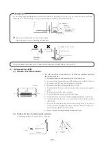
Accessories (only case of FDCA301~601 models)
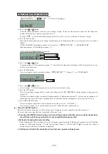
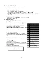
Confirm accessories shown below are attached in the bag with this installation manual.
1)
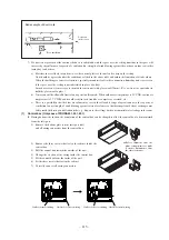
“Edging” for protection of electric wires from opening edge.
(b)
Selection of installation location
Select the installation location after obtaining the approval of customer.
1)
The place where the foundation can bear the weight of Outdoor unit.
2)
The place where there is no concern about leakage of combustible gas.
3)
The place where it is not stuffy.
4)
The place where free from thermal radiation of other thermal source.
5)
The place where flow of drain is allowed.
6)
The place where noise and hot air blast do not trouble neighboring houses.
7)
When the unit is installed at the particular location as shown below, corrosion or failure may be caused. Please consult
the dealer from which you purchased the air-conditioner.
a) The place where corrosive gas is generated (hot spring, etc.).
b) The place where wind containing salt blows (seaside area).
c) The place where enveloped by oil mist.
d) The place where there is a machine that radiates electromagnetic wave.
Request
¡
Restrict the height of obstruction wall in front of the discharge air port to the height of unit or less.
¡
Do not enclose around the unit by the obstruction. Secure the top space for 1 m or more.
¡
When installing the units side by side in series, secure a space of 10 mm between units.
¡
When installing the unit where there is a concern about the short circuit, attach the guide louver in front of
discharge air port to prevent the short circuit.
¡
When installing plural units in a group, secure sufficient intake space to prevent the short circuit.
¡
When installing the unit where it is covered by snow, provide appropriate snow break means.
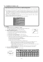
(c)
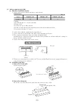
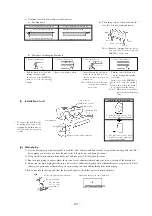
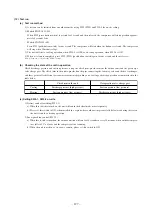
The minimum space for installation
Select the space considering the direction of refrigerant piping.
Open
space
Open
space
Distance
Installation
example
FDCVA151, 201, 251
1
FDCA301
FDCA401, 501, 601
Unit : mm
L
1
L
2
L
3
L
4
100
100
250
2
280
75
80
3
280
80
250
Open
space
Open
space
Open
space
Open
space
1
300
100
5
2
5
150
5
3
500
100
5
Open
space
Open
space
Open
space
1
300
150
5
2
5
300
5
3
500
150
5
Air
inlet
Air outlet
(Service space)
Air inlet
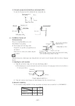
Special instructions for R410A air conditioning systems
●
Use only R410A refrigerant. R410A refrigerant is operated at about 1.6 times as high pressure as the conventional refrigerant
is.
●
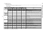
Air conditioning systems using R410A are equipped with different-diameter outdoor unit service valve charge ports and
check joints provided in the units so as to prevent wrong refrigerant from being charged by mistake. To achieve higher
strength resistible to refrigerant pressure, the dimensions of flaring and the across-the-flats measurement of a flare nut have
been changed for refrigerant piping. Therefore, please arrange dedicated R410A tools as listed in the table shown on the
below before you set to installation or service work.
●
Do not use a charge cylinder. The use of a charge cylinder will cause the refrigerant composition to change, resulting in
performance degradation falling short of the rated capacity.
●
In charging refrigerant, always take out refrigerant from a cylinder in the liquid phase.
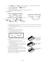
Dedicated R410 tools
Gauge manifold
Charge hose
Electronic scale for refrigerant charging
Torque wrench
Flare tool
Protrusion control copper pipe gauge
Vacuum pump adapter
Gas leak sensor
a
b
c
d
e
f
g
h

