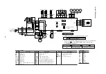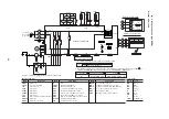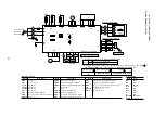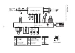
-
68
-
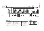
to outdoor unit
Power line
Signal line
1
3
2
Wireless specification
Wired specification
Remote controller
Remote
controller
ThC
X
X
CnB
Z
Y
Z
Y
TB1
FMI
LED5
LED3
CnM
1
2
WH
RD
RD
WH
Y
BL
RD
BK
BK
BK
BK
BK
BK
LED • R
LED • G
CnH
ThI-R1
ThI-A
CnN1
ThI-R2
1
2
3
1
2
3
4
G
S
3
BL/WH
J
R
BL
P
BR
OR
RD
LM
1
2
3
4
5
CnJ
RD
WH
BK
RD
WH
BK
2
3
1
CnC
TB
F (3.15A)
SW9
SW1
AMP
SW5
SW2
Y/GN
XR1
XR4
XR5
XR2
XR3
CnT
3
4
5
6
2
1
5
4
3
2
1
Option
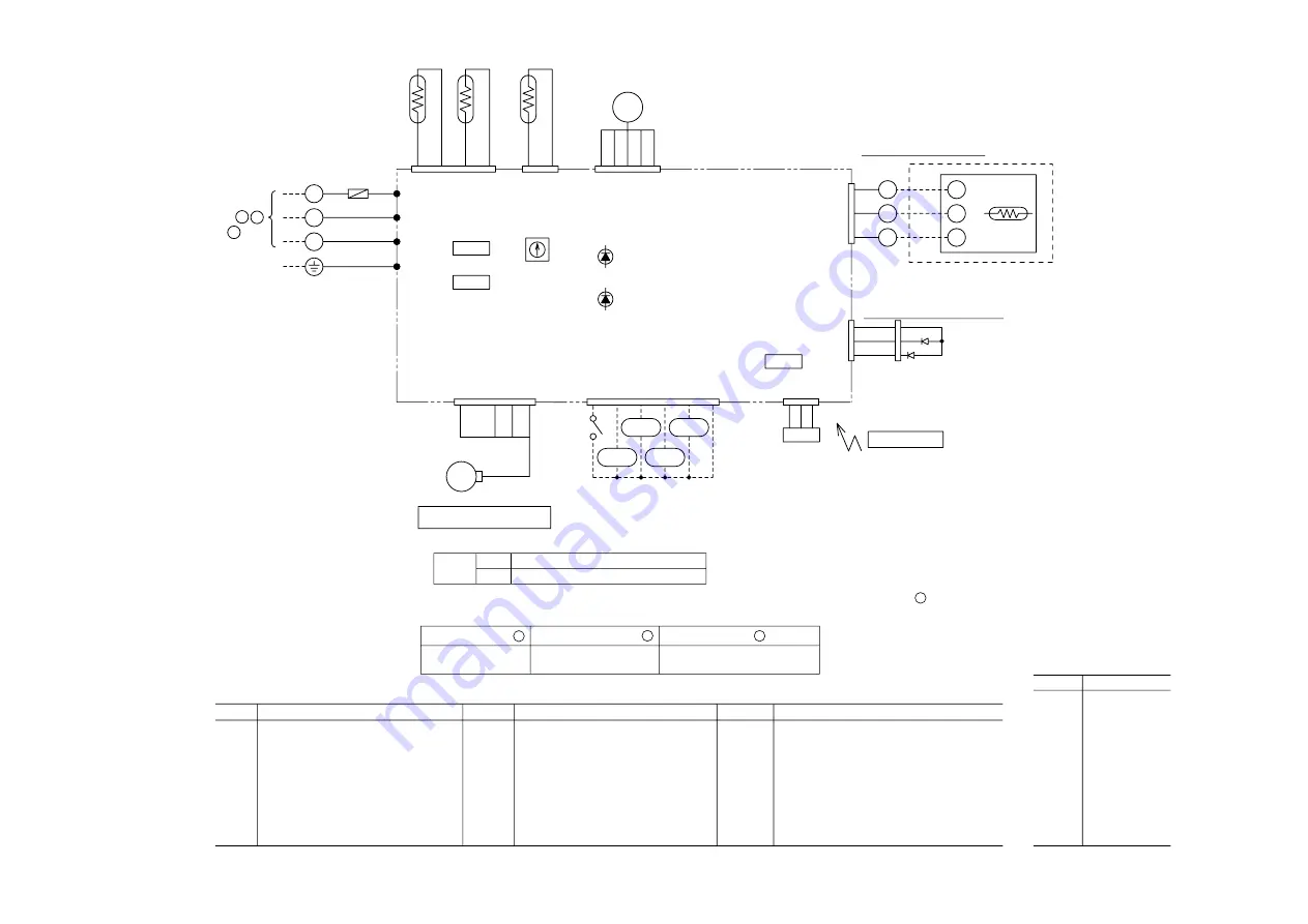
Printed circuit board
FMI
LM
ThI-A
ThI-R1
ThI-R2
ThC
SW1
SW2
Fan motor
Louver motor
Thermistor
Thermistor
Thermistor
Thermistor
Backup switch(ON/OFF)
Remote controller communication address
SW5-3,4
SW9-3
LED3
LED5
F
LED • R
LED • G
XR1
Filter sign
Emergency operation
Indication lamp(Yellow-Timer/Inspction alert)
Indication lamp(Green-Run)
Fuse
Indication lamp(Red)
Indication lamp(Green)
Operation output(DC12V output)
XR2
XR3
XR4
XR5
TB
CnA~Z
AMP
Heating output(DC12V output)
Thermo ON output(DC12V output)
Inspection output(DC12V output)
Remote operation input(volt-free contact)
Terminal block(
mark)
Connector
Wirelss receiver
Mark
Parts name
Mark
Parts name
Mark
Parts name
Meaning of marks
Color marks
BK
BL
BR
OR
RD
WH
Y
P
BL/WH
Y/GN
Black
Blue
Brown
Orange
Red
White
Yellow
Pink
Blue/White
Yellow/Green
Mark
Color
CnA
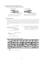
Blower fan tap switch
SW9-4
ON
OFF
Fan control, powerful mode
Fan control, mild mode
C
A
B
C
Function number
Function description
Setting
1
Set SW9-4 provided on the indoor unit PCB to OFF.
01
Hi CEILING SET
STANDARD
(Mild mode)
2
By means of function setting from the wired remote controller unit,set the setting of
2
"I/U FUNCTION
▲
" (indoor unit function) to "STANDARD (Mild mode)."
Model FDKNA301

