background image

– 

 –

 '17 • KX-T-259

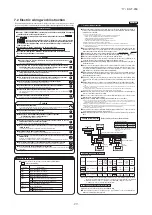
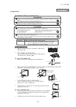
Check list after installation

Check the following items after all installation work completed.

Check if;
The indoor and outdoor units are fixed securely?
Inspection for leakage is done?
Insulation work is properly done?
Water is drained properly?
Power source voltage is same as mentioned in the model name plate ?
There is mis-wiring or mis-connection of piping?
Earth wiring is connected properly?
Cable size comply with specified size?
Any obstacle blocks air flow on air inlet and outlet?

Check

Expected trouble
Falling, vibration, noise
Insufficient capacity
Water leakage
Water leakage
PCB burnt out, not working at all
Electric shock
PCB burnt out, not working at all
Insufficient capacity

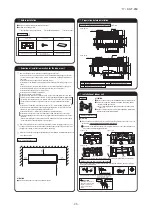
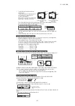
Installation of indoor unit (continued)

Wiring-out position and wiring connection (continued)

Refrigerant pipe

 Drain pipe (continued)

Be sure to use new pipes for the refrigerant pipes. Use the flare nut attached to the product or

a nut compatible with JIS B 8607, Class 2.

Regarding whether existing pipes can be reused or not, and the washing method, refer to the instruction manual of the
outdoor unit, catalogue or technical data.
1) In case of reuse: Do not use old flare nut, but use the one attached to the unit or compatible with JIS B 8607, Class 2.
2) In case of reuse: Flare the end of pipe replaced partially for R410A.

Use phosphorus deoxidized copper alloy seamless pipe (C1220T specified in JIS H3300) for refrigeration pipe installation.

In addition, make sure there is no damage both inside and outside of the pipe, and no harmful
substances such as sulfur, oxide, dust or a contaminant stuck on the pipes.

Do not use any refrigerant other than R410A.

Using other refrigerant except R410A (R22 etc.) may degrade inside refrigeration oil. And air getting into
refrigeration circuit may cause over-pressure and resultant it may result in bursting, etc.

Store the copper pipes indoors and seal the both end of them until they are brazed in order to avoid any dust, dirt or

water getting into pipe. Otherwise it will cause degradation of refrigeration oil and compressor breakdown, etc.

Use special tools for R410A refrigerant.

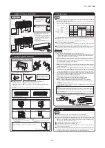
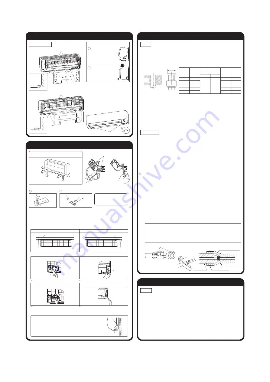
Address setting
Remove the front panel of indoor unit and the control cover, it is possible to change address setting.
1. Remove the front panel

 Remove the air inlet panel.

 Remove the 2 screws in the cap of bottom panel. (Type 15 - 56 only)

Remove the 2 hooks of left and right side and then bottom panel can be removed. (Type 15
- 56 only)

 Remove the screws (Type 15 - 56: 2 screws, Type 71, 90: 5 3 screws (in the cap))

Remove the upper latches and then front panel can be removed. (Type 15 - 56: 4 latches,

Type 71, 90: 5 latches)

2. Install the front panel

Cover the unit with the front panel and fix upper latches (Type 15 - 56: 4 latches, Type 71,

90: 5 latches)

Fix the front panel with the screws (Type 15 - 56: 2 screws, Type 71, 90: 5  3 screws
(in the cap))

Install the 2 hooks of left and right side and then bottom panel can be installed. (Type 15 - 56
only)

 Fix the bottom panel with 2 screws in the cap. (Type 15 - 56 only)

 Install the air inlet panel.

Caution

D

Protruding

dimension

Flare die

d

mm

6.35

9.52

12.7

15.88

19.05

For R410A Conventional tool

Pipe dia.

Min. pipe

wall thickness

Protruding dimension for flare, mm

Rigid (Clutch type)

Flare O.D.

Flare nut

tightening torque

0

-

0.5

0.7

-

1.3

D

mm

8.9

-

 9.1

12.8

-

13.2

16.2

-

16.6

19.3

-

19.7

23.6

-

24.0

N·m

14

-

 18

34

-

 42

49

-

 61

68

-

 82

100

-

 120

mm

0.8

0.8

0.8

1

1.2

1. Remove the flare nut and blind flanges on the pipe of the indoor unit.

※ 

Make sure to loosen the flare nut with holding the nut on pipe side with a spanner and giving torque to the

nut with another spanner in order to avoid unexpected stress to the copper pipe, and then remove them.

(Gas may come out at this time, but it is not abnormal.)

Pay attention whether the flare nut pops out. (as the indoor unit is sometimes pressured.)

2. Make a flare on liquid pipe and gas pipe, and connect the refrigeration pipes on the indoor unit.

Bend radius of pipe must be 4D or larger. Once a pipe is bent, do not readjust the bending.

Do not twist a pipe or collapse to 2/3D or smaller.

Do a flare connection as follows:

Make sure to loosen the flare nut with holding the nut on pipe side with a spanner and giving

torque to the nut with another spanner in order to avoid unexpected stress to the copper pipe,

and then remove them.

When fastening the flare nut, align the refrigeration pipe with the center of flare nut, screw

the nut for 3-4 times by hand and then tighten it by spanner with the specified torque

mentioned in the table above. Make sure to hold the pipe on the indoor unit securely by a

spanner when tightening the nut in order to avoid unexpected stress on the copper pipe.

3. Cover the indoor unit’s flare-connected joints, after they are checked for a gas leak, with an

indoor unit heat insulating material and then wrap them with a tape with an attached insula-

tion pad placed over the heat insulating material’s slit area.

Make sure to insulate both gas pipes and liquid pipes completely.

※ 

Incomplete insulation may cause dew condensation or water dropping.

Use heat-resistant (120 °C or more) insulations on the gas side pipes.

In case of using at high humidity condition, reinforce insulation of refrigerant pipes.

Surface of insulation may cause dew condition or water dropping, if insulations are not 

reinfoced.

4. Refrigerant is charged in the outdoor unit.

As for the additional refrigerant charge for the indoor unit and piping, refer to the installation

manual attached to the outdoor unit.

Work procedure

Refrigerating machine oil should not be applied to the threads of union or external surface of flare. It

is because, even if the same tightening torque is applied, the oil is likely to decrease the slide friction

force on the threads and increase, in turn, the axial component force so that it could crack the flare

by the stress corrosion.

Refrigerating machine oil may be applied to the internal surface of flare only.

Caution:

 Arrange the drain hose in a downward angle

 Avoid the following drain piping.

When the extended drain hose is present inside the room, always use a shield pipe (prepare
on site) and ensure it is thermally insulated

Shield pipe

Drain hose

Extended drain hose

When it is exposed indoor.

3 Pour water to the drain pan located under the heat exchanger, and ensure that water is discharged 

the outdoor.
(For removal of the front panel, refer to 

Wiring-out position and wiring connection

   in this manual.

1. A general-purpose hard PVC pipe VP16 can be connected to the drain hose tip as a part of

drain piping.

2. Drain piping must be given a descending grade so that drain water may flow smoothly and it

must not have any trap or bump within the system.
(The pipe can be routed through the left, right, rear or bottom of the unit)
Hard PVC pipes (VP16) laid indoors must be kept warm.

Drain pipe

Caution

Install the drain pipe according to the installation manual in order to drain properly.
Imperfection in draining may cause flood indoors and wetting the household goods,etc.

Do not put the drain pipe directly into the ditch where toxic gas such as sulfur, the other harmful and

inflammable gas is generated. Toxic gas would flow into the room and it would cause serious
damage to user’s health and safety (some poisoning or deficiency of oxygen). In addition, it may
cause corrosion of heat exchanger and bad smell.
Connect the pipe securely to avoid water leakage from the joint.
Insulate the pipe properly to avoid condensation drop.
Check if the water can flow out properly from both the drain outlet on the indoor unit and the end
of the drain pipe after installation.
Make sure to make descending slope of greater than 1/100 and do not make up-down bend and/or trap in 
the midway. In addition, do not put air vent on the drain pipe. Check if water is drained out properly from
the pipe during commissioning. Also, keep sufficient space for inspection and maintenance.

Fixing of indoor unit

Shaping of pipes and drain hoses

<In case of piping in the right rear direction>

Shaping of pipes

Tape wrapping

Pipe

Drain hose

Make sure that wires are connected

securely onto the terminal block,

before you wrap them with a tape

after shaping the pipe.

Installation

board

Indoor unit base latch

Wall

Installation board

Indoor unit

Latch (2 locations)

Installation board

Installation

board

Indoor unit base latch

Wall

Indoor unit

Latch (2 locations)

Type 71, 90

Type 15~56

t)PXUPSFNPWFUIFJOEPPSVOJUGSPN

the

installation board

Push up at the marked portion of the indoor unit 

base lower latch, and slightly pull it toward you. 

(both right and left hand sides) (The indoor unit 

base lower latch can be removed from the 

installation board)

Push up the indoor unit upward so that it can be 

removed from installation board.

Latch

2

1

Gently push the lower part to 
secure the unit.

Pass the pipe through the hole 
in the wall, and hook the upper 
part of the indoor unit to the 
installation board.

Cut out the panel smoothly along the 

line in case of side or bottom piping.

Piping is possible in the rear, left, left rear, left downward,
right or downward direction.

Right

Right rear

Right

downward

Left

rear

Left downward

Left

Tape only the portion that goes through the wall.
Always tape the wiring with the piping.
The connecting wires must be wrapped together with the pipe.

Hold the bottom of the 

piping and fix direction 

before stretching it and 

shaping it.

Piping in the left direction

Piping in the right rear direction

Piping in the left rear direction

Piping in the right direction

[Top view]

t.BUUFSTPGTQFDJBMOPUJDFXIFOQJQJOHGSPNMFGUPSDFOUSBMSFBSPG

the unit.

Left-hand-side piping

Right-hand-side piping

[Drain hose changing procedures]

1. Remove the drain hose

2. Remove the drain cap.

Remove it with hand or pliers.

Remove the screw and drain hose, making it rotate.

3. Insert the drain cap.

4. Connect the drain hose.

Insert the drain cap which was removed at procedure “2” 

securely using a hexagonal wrench etc.

Note: Be careful that If it is not inserted securely, water 

leakage may occur.

Insert the drain hose securely, making rotate. And install the 

screw.

Note: Be careful that If it is not inserted securely, water 

leakage may occur.

screw

cap

Band (Prepare on site)

Band (Prepare on site)

Insulation

(Prepare on site)

Pipe cover (Prepare on site)

<The case of using reinforced insulation at the outside of unit>

Vinyl tape

Use an attached insulation pad for heat insulation.

Position it so that the slit area faces upward.

Higher than specified

Wavy

The drain hose 
tip is in water.

The gap to the ground is 
5 cm or less.

The drain hose 
tip is in the gutter.

Odor from 
the gutter

Electrical installation work must be performed according to the installation manual by an
electrical installation service provider qualified by a power provider of the country, and be
executed according to the technical standards and other regulations applicable to electrical
installation in the country.
Be sure to use an exclusive circuit.
Use specified cord, fasten the wiring to the terminal securely, and hold the cord securely in
order not to apply unexpected stress on the terminal.
Do not put both power source line and signal line on the same route. It may cause miscom-
munication and malfunction.
Be sure to do D type earth work.


For the details of electrical wiring work, see attached instruction manual for electrical wiring
work.

Wiring-out position and wiring connection

Signal side

terminal block

Power source side

terminal block

Earth

Band

Band

Superlink line

Remote control line

Power source line

In case of band is over length,

cut off the band.

Pull the air inlet panel at both ends of lower part and release latches, then pull up the panel until
you feel resistance. (The panel stops at approx 60 - 70° open position.)

 Remove the screw and the lid.

 Connect wiring securely to the terminal block.

 Fix wiring the clamp securely, in order not to transmit unexpected stress on the terminal.

 Fix the lid and the screw.

 Close the air inlet panel.

(Note)
Connect wiring to the terminal block, check number on label of the terminal block.

Wall

Gutter

Pipe accommodating section

Since this air-conditioner has been designed to collect dew drops on the rear 
surface to the drain pan, do not attach the power cable above the gutter.

Installation Steps

Signal side

terminal block

Power source side

terminal block

Earth

Band

Band

Superlink line

Remote control line

Power source line

PHA012D401

Type 15-56

Type 15-56

Type 71, 90

Type 15-56

Type 71, 90

Type 71, 90

Air inlet panel

Front panel

Front panel

Air inlet panel

Screw

Screw (in the cap)

Latch

Screw

Screw

Control cover

Control cover

Address switch

Bottom panel

Screw (in the cap)

Screw

Latch

Address switch

Lid

Type 15-56

Type 71, 90

Lid

Summary of Contents for FDK22KXZE1

Page 1: ... Regarding the outdoor unit KXZ series refer to the No 14 KX T 223 No 15 KX T 227 and Note No 16 KX DB 225D INDOOR UNIT Wall mounted type FDK22KXZE1 28KXZE1 36KXZE1 45KXZE1 56KXZE1 71KXZE1 KXZ series VRF INVERTER MULTI SYSTEM AIR CONDITIONERS ...

Page 2: ...ol function by the wired remote control 48 1 Model RC EX3 33 2 Model RC E5 40 6 CAPACITY TABLES 8 3 Operation control function by the indoor control 51 9 SYSTEM TROUBLESHOOTING PROCEDURE 67 9 1 Basics of troubleshooting 67 9 2 Contents of troubleshooting 68 9 3 Instruction of how to replace PCB 99 2 14 11 19 9 4 Indoor PCB setting 101 10 OPTION PARTS 10 1 Wireless kit RCN K E2 RCN K71 E2 102 110 1...

Page 3: ...le Not possible Not possible Air filter Q ty Polypropylene net 2 Washable Polypropylene net 2 Washable Polypropylene net 2 Washable Polypropylene net 2 Washable Polypropylene net 2 Washable Shock vibration absorber Rubber sleeve for fan motor Rubber sleeve for fan motor Rubber sleeve for fan motor Rubber sleeve for fan motor Rubber sleeve for fan motor Insulation noise heat Polyurethane form Polyu...

Page 4: ...intake Not possible Air filter Q ty Polypropylene net 2 Washable Shock vibration absorber Rubber sleeve for fan motor Insulation noise heat Polyurethane form Operation control Remote control switch wired RC EX3 RC E5 RCH E3 wireless RCN K71 E2 Room temperature control Thermostat by electronics Safety equipment Overload protection for fan motor Frost protection thermostat Installation data Refriger...

Page 5: ...5 1 21 0 88 0 33 0 00 0 00 0 00 0 00 0 00 FDK36KXZE1 13 0 1 21 0 88 0 33 0 00 0 00 0 00 0 00 0 00 FDK45KXZE1 13 0 1 21 0 88 0 33 0 00 0 00 0 00 0 00 0 00 FDK56KXZE1 13 0 1 21 0 88 0 33 0 00 0 00 0 00 0 00 0 00 FDK71KXZE1 20 0 2 64 1 87 0 77 0 00 0 00 0 00 0 00 0 00 Option parts RCN K E2 0 7 0 20 0 18 0 02 0 00 0 00 0 00 0 00 0 00 RCN K71 E2 0 7 0 20 0 18 0 02 0 00 0 00 0 00 0 00 0 00 Indoor unit o...

Page 6: ...or installation and service when viewing from the front Unit mm Note 1 The model name label is attached on the right side of the unit 45 45 870 290 Outlet for downward piping Refer to the top view 230 3 60 13 530 450 190 185 43 170 585 13 Service space Unit Service space Service space Installation board 142 5 142 5 150 50 9 47 268 47 80 100 Terminal block 60 35 35 60 210 55 55 537 528 Service spac...

Page 7: ...d service when viewing from the front 768 157 48 240 6 7 322 4 214 5 214 5 883 157 10 3 262 19 43 5 64 64 55 47 53 77 47 1197 339 55 150 50 Service space Service space Service space 15 100 783 715 759 55 Installation plate Unit mm Note 1 The model name label is attached on the underside of the indoor unit Outlet for down piping Refer to the above view 60 240 43 470 363 5 363 5 568 5 568 5 11 60 Te...

Page 8: ... PJZ000Z321 a Wired remote control Model RC EX3 Installation space R C cable 0 3mm2 2 cores Adapted to RoHS directive Exterior appearance Munsell color Pearl white N8 5 near equivalent 2 Remote control Option parts ...

Page 9: ...res 2 0mm2 2 cores Under 300m Under 400m Under 600m Upper part Lower part Lower case Sheath Upper cace Board Wiring Upper Lower X Y Sheath Upper cace Board Wiring Upper Lower Y X Tighten the screws after cutting off the thin part of screw mounting part Embedded mounting The peeling off length of sheath The peeling off length of sheath In case of pulling out from upper left In case of pulling out f...

Page 10: ... 17 KX T 259 b Wireless remote control RCN EK2 Unit mm 60 24 167 ...

Page 11: ... R D W H Y E B L CNF1 WH 4 3 1 5 6 1 Meaning of marks I 5 1 indicates wiring on site 2 Use twin core shielded cord 0 75 1 25mm at signal line between 2 indoor unit and outdoor unit and signal line between indoor units 3 Use twin core cord 0 3mm at remote control line 2 See spec sheet of remote control in case that the total length is more than 100m 4 Do not put signal line and remote control line ...

Page 12: ...m Unit Mike Center low points 1m Model FDK22 28KXZE1 P Hi Noise Level Cooling 38 dB A Heating 38 dB A Cooling Heating 10 10 20 30 40 50 60 70 63 125 250 500 1000 2000 4000 8000 Mid octave band frequency Hz Sound pressure level dB Standard 2 10 5 Pa 20 30 40 50 60 70 N50 N40 N60 N70 N20 N30 10 20 30 40 50 60 70 63 125 250 500 1000 2000 4000 8000 Mid octave band frequency Hz Sound pressure level dB ...

Page 13: ...ve band frequency Hz Sound pressure level dB Standard 2 10 5 Pa 20 30 40 50 60 70 N50 N40 N60 N70 N20 N30 10 Model FDK56KXZE1 P Hi Noise Level Cooling 43 dB A Heating 44 dB A Cooling Heating 10 20 30 40 50 60 70 63 125 250 500 1000 2000 4000 8000 Mid octave band frequency Hz Sound pressure level dB Standard 2 10 5 Pa 20 30 40 50 60 70 N50 N40 N60 N70 N20 N30 10 ...

Page 14: ... Hi Noise Level Cooling 42 dB A Heating 42 dB A Cooling Heating 10 20 30 40 50 60 70 63 125 250 500 1000 2000 4000 8000 Mid octave band frequency Hz Sound pressure level dB Standard 2 10 5 Pa 20 30 40 50 60 70 N50 N40 N60 N70 N20 N30 10 ...

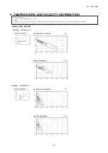
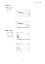
Page 15: ... and velocity distribution at the center of air outlet within the published conditions In the actual installation they may differ from the typical figures under the influence of air temperature conditions ceiling height operation conditions and obstacles Models FDK22 28KXZE1 P Hi P Hi Temperature distribution Velocity distribution Temperature distribution Velocity distribution ...

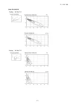
Page 16: ... 15 17 KX T 259 Model FDK36KXZE1 P Hi P Hi Temperature distribution Velocity distribution Temperature distribution Velocity distribution ...

Page 17: ... 16 17 KX T 259 Model FDK45KXZE1 P Hi P Hi Temperature distribution Velocity distribution Temperature distribution Velocity distribution ...

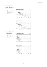
Page 18: ... 17 17 KX T 259 Model FDK56KXZE1 P Hi P Hi Temperature distribution Velocity distribution Temperature distribution Velocity distribution ...

Page 19: ... 18 17 KX T 259 Model FDK71KXZE1 P Hi P Hi Temperature distribution Velocity distribution Temperature distribution Velocity distribution ...

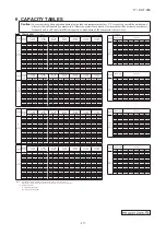
Page 20: ...53 1 83 1 65 1 90 1 65 1 92 1 63 1 97 1 70 2 01 1 66 Indoor air temperature Outdoor 21 DB 23 DB 26 DB 27 DB 28 DB 31 DB 33 DB Air flow air temp 14 WB 16 WB 18 WB 19 WB 20 WB 22 WB 24 WB DB TC SHC TC SHC TC SHC TC SHC TC SHC TC SHC TC SHC DB WB 16 DB 18 DB 20 DB 22 DB 24 DB 10 0 00 1 41 1 22 1 69 1 38 1 83 1 41 1 95 1 43 2 18 1 54 2 26 1 51 19 8 20 1 08 1 08 1 08 1 08 1 08 12 0 00 1 41 1 22 1 69 1 ...

Page 21: ...B 24 WB DB TC SHC TC SHC TC SHC TC SHC TC SHC TC SHC TC SHC DB WB 16 DB 18 DB 20 DB 22 DB 24 DB 10 0 00 1 80 1 45 2 15 1 64 2 33 1 68 2 48 1 70 2 77 1 84 2 88 1 79 19 8 20 1 39 1 39 1 39 1 39 1 39 12 0 00 1 80 1 45 2 15 1 64 2 33 1 68 2 47 1 70 2 76 1 83 2 87 1 79 17 8 18 1 48 1 48 1 48 1 48 1 48 14 0 00 1 80 1 45 2 15 1 64 2 33 1 68 2 47 1 70 2 75 1 83 2 86 1 78 15 7 16 1 57 1 57 1 57 1 57 1 57 1...

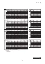
Page 22: ... WB 24 WB DB TC SHC TC SHC TC SHC TC SHC TC SHC TC SHC TC SHC DB WB 16 DB 18 DB 20 DB 22 DB 24 DB 10 0 00 2 29 1 86 2 74 2 11 2 96 2 15 3 15 2 18 3 53 2 36 3 67 2 30 19 8 20 1 76 1 76 1 76 1 76 1 76 12 0 00 2 29 1 86 2 74 2 11 2 96 2 15 3 15 2 18 3 52 2 35 3 65 2 29 17 8 18 1 88 1 88 1 88 1 88 1 88 14 0 00 2 29 1 86 2 74 2 11 2 96 2 15 3 14 2 18 3 51 2 35 3 63 2 28 15 7 16 1 99 1 99 1 99 1 99 1 99...

Page 23: ...WB 24 WB DB TC SHC TC SHC TC SHC TC SHC TC SHC TC SHC TC SHC DB WB 16 DB 18 DB 20 DB 22 DB 24 DB 10 0 00 2 95 2 31 3 53 2 61 3 82 2 69 4 06 2 72 4 55 2 94 4 72 2 86 19 8 20 2 28 2 28 2 28 2 28 2 28 12 0 00 2 95 2 31 3 53 2 61 3 82 2 69 4 06 2 72 4 53 2 93 4 70 2 85 17 8 18 2 42 2 42 2 42 2 42 2 42 14 0 00 2 95 2 31 3 53 2 61 3 82 2 69 4 05 2 72 4 52 2 92 4 68 2 84 15 7 16 2 57 2 57 2 57 2 57 2 57 ...

Page 24: ...B 24 WB DB TC SHC TC SHC TC SHC TC SHC TC SHC TC SHC TC SHC DB WB 16 DB 18 DB 20 DB 22 DB 24 DB 10 0 00 3 67 2 73 4 39 3 10 4 75 3 19 5 05 3 24 5 66 3 49 5 88 3 40 19 8 20 3 43 3 43 3 43 3 43 3 43 12 0 00 3 67 2 73 4 39 3 10 4 75 3 19 5 05 3 24 5 64 3 49 5 85 3 39 17 8 18 3 65 3 65 3 65 3 65 3 65 14 0 00 3 67 2 73 4 39 3 10 4 75 3 19 5 04 3 23 5 62 3 48 5 83 3 37 15 7 16 3 87 3 87 3 87 3 87 3 87 1...

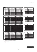
Page 25: ... 24 WB DB TC SHC TC SHC TC SHC TC SHC TC SHC TC SHC TC SHC DB WB 16 DB 18 DB 20 DB 22 DB 24 DB 10 0 00 4 70 3 80 5 62 4 30 6 08 4 40 6 47 4 46 7 24 4 81 7 52 4 69 19 8 20 3 70 3 70 3 70 3 70 3 70 12 0 00 4 70 3 80 5 62 4 30 6 08 4 40 6 46 4 46 7 22 4 80 7 49 4 67 17 8 18 3 94 3 94 3 94 3 94 3 94 14 0 00 4 70 3 80 5 62 4 30 6 08 4 40 6 45 4 45 7 19 4 79 7 46 4 66 15 7 16 4 18 4 18 4 18 4 18 4 18 16...

Page 26: ... unit near the location where there is possibility of flammable gas leakages If the gas leaks and gathers around the unit it could cause fire Do not install and use the unit where corrosive gas such as sulfurous acid gas etc or flammable gas such as thinner petroleum etc may be generated or accumulated or volatile flammable substances are handled It could cause the corrosion of heat exchanger brea...

Page 27: ...2 3 4 5 6 7 8 9 10 11 12 13 14 15 16 17 0 25 19 2 6 20 21 18 039 F Drilling of holes and fixture of sleeve Option parts Sleeve Sleeve Indoor side Outdoor side Thicknese of the wall 5 65 Installed state When drilling the wall that contains a metal lath wire lath or metal plate be sure to use pipe hole sleeve sold separately Drill a hole with whole core drill In case of right rear piping draw out cu...

Page 28: ...l is likely to decrease the slide friction force on the threads and increase in turn the axial component force so that it could crack the flare by the stress corrosion Refrigerating machine oil may be applied to the internal surface of flare only Caution A A W o 3 Pou the Fo 1 A g dra 2 Dra mu Th Ha Drain pipe Caution Install the drain pipe according to the installation manual in order to drain pr...

Page 29: ...oor For removal of the front panel refer to Wiring out position and wiring connection in this manual 1 A general purpose hard PVC pipe VP16 can be connected to the drain hose tip as a part of drain piping 2 Drain piping must be given a descending grade so that drain water may flow smoothly and it must not have any trap or bump within the system The pipe can be routed through the left right rear or...

Page 30: ...used as a Heat Recovery 3 pipe Systems refer to the installation manual of a branching control option Remote control Be sure to have the electrical wiring work done by qualified electrical installer and use exclusive circuit Power source with insufficient capacity and improper work can cause electric shock and fire Use specified wire for electrical wiring fasten the wiring to the terminal securely...

Page 31: ...XR2 XR3 XR4 XR5 Common Output 1 Output 2 Output 3 Output 4 Remote ON OFF switch or timer contactor AC100V DC12V DC24V Input 1 XR6 AC100V DC12V DC24V Input 2 Note 1 0 3 mm2 2 m Note 1 0 3 mm2 2 m Note 1 To be no longer than 2 m 0 75mm2 0 2 m Butt connecting contactor Red Black Yellow Blue Brown Orange Remote ON OFF monitor kit Applicable range 0 75 1 25 mm2 XR5 XR6 White Black Yellow Blue Brown Ora...

Page 32: ... mode Cooling Heating is done by the both factors of the set temp and outdoor air temp The set temp and fan speed can be set A 7 External Ventilation When the ventilator is combined On Off operation of the external ventilator can be done It is necessary to set from Menu Service setting R C function settings Ventilation setting If the Independent is selected for the ventilation setting the ventilat...

Page 33: ... B 3 IU settings Fan speed setting The fan speed for indoor units can be set B Filter sign The setting of filter sign display timer can be done from following patterns B Service password External input 1 The connect of control by external input 1 can be changed B External input 1 signal The type of external input 1 signal can be changed B External input 2 The connect of control by external input 2...

Page 34: ... source before starting electrical work Otherwise it could result in electric shocks break down or malfunction Do not modify the unit It could cause electric shocks fire or break down Be sure to turn OFF the power circuit breaker before repairing inspecting the unit Repairing inspecting the unit with the power circuit breaker turned ON could cause electric shocks or injury Please read this manual ...

Page 35: ...ectric shocks fire or break down Use the specified cables for wiring and connect them securely with care to protect electronic parts from external forces Improper connections or fixing could cause heat generation fire etc Seal the inlet hole for remote control cable with putty If dew water insect etc enters through the hole it could cause electric shocks fire or break down If dew or water enters th...

Page 36: ...ation occurs on the remote control Where the remote control gets wet 3 Accurate room temperature may not be detected using the temperature sensor of the remote control Where the average room temperature cannot be detected Place near the equipment to generate heat Place affected by outside air in opening closing the door Place exposed to direct sunlight or wind from air conditioner Where the differ...

Page 37: ...ength is longer than 100 m the max size for wires used in the R C case is 0 5 mm2 Connect them to wires of larger size near the outside of R C When wires are connected take measures to prevent water etc from entering inside 200 m 0 5 mm2 x 2 cores 300m 0 75 mm2 x 2 cores 400m 1 25 mm2 x 2 cores 600m 2 0 mm2 x 2 cores Secure the installation space shown in the figure For the installation method emb...

Page 38: ...s Viewed from front 37 23 23 固定穴 18 3 83 5 120 19 120 37 23 23 19 120 Fixing holes 83 5 120 18 3 PCB side Viewed from rear 8 50 200 壁 電線管 ロ ッ クナッ ト スイ ッ チ ボ ッ クス パテで シール する こ と リ モコ ン配線 下ケース配線穴 ブッ シ ング センサー USB 端子 Wall Conduit Sensor USB port Terminal block Locknut Bushing Switch box Seal with putty R C cable When wires are passed through the bottom case fix the bottom case at 2 places on the swit...

Page 39: ...ke care not to pinch the sheath Tighten by hand 0 7 N m or less the wire connection If the wire is connected using an electric driver it may cause failure or deformation In case of exposing wiring When the wiring is taken out from the upper center or upper left of R C Cut out the thin wall sections on the cases for the size of wire Fix the bottom R C case on a flat surface with two wood screws In ...

Page 40: ...er lower flap control Left right flap control Ventilation setting Auto restart Auto temp setting Auto fan speed IU settings Service Maintenance IU address Next service date Operation data Error display Error history Display erase anomaly data Reset periodical check Saving IU settings Special settings Erase IU address CPU reset Restore of default setting Touch panel calibration Indoor unit capacity...

Page 41: ... of remote control lower case with a nipper or knife and grind burrs with a file etc Install the lower case to the flat wall with attached two wooden screws Connect the remote cont terminal block Connect the terminal of r with the terminal of indoo X and Y are no polarity Wiring route is as shown depending on the pulling The wiring inside the rem The sheath should be pe The peeling off length of P...

Page 42: ...rminal of indoor unit X Y X and Y are no polarity Wiring route is as shown in the right diagram depending on the pulling out direction The wiring inside the remote control case should be within 0 3mm2 recommended to 0 5mm2 The sheath should be peeled off inside the remote control case The peeling off length of each wire is as below Pulling out from upper left Pulling out from upper center X wiring...

Page 43: ... for over three seconds The indication changes to FUNCTION SET 2 Press button once and change to the TEMP RANGE indication 3 Press SET button and enter the temperature range setting mode 4 Select UPPER LIMIT or LOWER LIMIT by using button 5 Press SET button to fix 6 When UPPER LIMIT is selected valid during heating Press SET button to fix Indication example UPPER 26 C Displayed for two seconds Aft...

Page 44: ...g 2 0 C increase in return air temperature of indoor unit To be reset producing 1 5 C increase in return air temperature of indoor unit To be reset producing 1 0 C increase in return air temperature of indoor unit To be reset producing 1 0 C increase in return air temperature of indoor unit To be reset producing 1 5 C increase in return air temperature of indoor unit To be reset producing 2 0 C in...

Page 45: ...or unit function Operation message Function description setting description Function No Fixing button Finishing button 7 2 1 6 Starting button Previous screen button Indoor unit selection button Press SET button 6 DATA LOADING Indication with blinking Display is changed to 01 7 DATA LOADING Blinking for 2 to 23 seconds to read the data 1 2 3 Press SET button On the occasion of remote control funct...

Page 46: ...ce can be changed LCD With backlight A tap on the LCD lights the backlight The backlight turns off automatically if there is no operation for certain period of time Lighting period of the backlight lighting can be changed If the backlight is ON setting when the screen is tapped while the backlight is turned off the backlight only is turned on Operations with switches and are excluded USB port USB ...

Page 47: ... adjustment mode Cover AIR CON No button Display the indoor unit number connected to this remote control CHECK button This button is used at servicing TEST button This button is used during test operation Weekly timer display Displays the settings of the weekly timer Operation setting display area Displays setting temperature airflow volume operation mode and oparation message Operation check indi...

Page 48: ...s pressed once again it stops operating MODE button Every time this button is pressed displays switch as below AUTO COOL HEAT FAN DRY TEMP button Change the set temperature by pressing or button FAN SPEED button The fan speed is switched in the following order 1 speed 2 speed 3 speed 4 speed AUTO 1 speed U D button Used to determine the up down louver position L R button Used to determine the left...

Page 49: ... CPU reset Reset CPU from the remote control as follows TOP screen Menu Service setting Service Maintenance Service password The selected screen is displayed The selected screen is displayed Service Maintenance 2 Special settings CPU reset Microcomputers of indoor unit and outdoor unit connected are reset State of restoration after power failure 3 Power failure compensation function Electric power...

Page 50: ... Indoor function items are saved in the memory of indoor unit g Weekly timer peak cut timer or silent mode timer settings h Remote control function setting Please check the I U Set clock first on the initializing screen set the timer Other thanA C is connected If the following a to c appear check and repair as follows Communication check screen This appears if communications cannot be established ...

Page 51: ...de the state of stop is memorized Although the timer mode is cancelled at the recovery from power failure the setting of weekly timer is changed to the holiday setting for all weekdays b Operation mode c d Room temperature setting e Louver auto swing stop However the stop position 4 position is cancelled so that it returns to Position 1 f Remote control function items which have been set with the ...

Page 52: ...ation is not performed regardless of the temperature shown at right Room temperature Setting temperature 3 3 Cooling operation Heating operation Room temperature detected with Thi A deg 59 56 Heating operation stopped cooling Heating OK Indoor heat exchanger temperature C b The following automatic controls are performed other than a above i Cooling or heating operation mode is judged according to ...

Page 53: ...ng Heating Dehumidifying Fan Operation Functional item Thermostat ON Thermostat ON Thermostat OFF Thermostat OFF Hot start Defrost Compressor 4 way valve Outdoor unit fan Indoor unit fan Drain pump 3 2 2 Thermostat ON Thermostat OFF 2 2 Notes 1 Operation Stop Turned ON OFF by the control other than the room temperature control 2 ON during the drain motor delay control 3 Drain pump ON setting may b...

Page 54: ... vi Weekly timer Set the ON or OFF timer for a week Up to 8 patterns can be set for a day The day off setting is provided for holidays and non business days Note 1 It is necessary to set the clock to use the weekly timer vii Combination of patterns which can be set for the timer operations Note 1 Allowed Not Sleep time Sleep time Set OFF timer by hour Weekly timer Set ON timer by hour Set OFF time...

Page 55: ...erates with the set air flow volume regardless of the thermostat ON OFF 2 Once the fan motor is changed from OFF to ON during the thermostat ON the indoor fan motor is not turned OFF even if the heat exchanger thermistor detects lower than 25 C Note 1 When the defrost operation signal is received it complies with the fan control during defrost operation 3 Once the hot start is completed it will no...

Page 56: ...trol 1 Press the LOUVER button to operate the swing louver when the air conditioner is operating SWING is displayed for 3 seconds and then the swing louver moves up and down continuously 2 the swing louver at a position press one time the LOUVER button while the swing louver is moving so that four stop positions are displayed one after another per second When a desired stop position is displayed p...

Page 57: ... indoor fan stops 2 Indoor fan OFF is for 5 minutes After the 5 minutes the indoor fan is operated at ULo for 2 minutes In the meantime the louver is controlled at level 3 After operating at ULo for 2 minutes the indoor fan moves to the state of 1 above 4 If the thermostat is turned ON it moves to the hot start control 5 When the heating thermostat is turned OFF the remote control displays the tem...

Page 58: ...s OFF ON ON ON Stopped by remote control etc 1 1 Even when the thermostat of another indoor unit is turned ON after the compressor ON the thermostat is not turned OFF for 2 minutes after the compressor ON 1 OFF OFF 3 minutes delay Thermostat OFF in the condition of item 8 Compressor Indoor unit A Thermostat Indoor unit B Thermostat b When the oil return control has started while the thermostat is ...

Page 59: ...5 16 PAC T 251 c Operation check mode There is no communication with the outdoor unit but it allows performing operation in respective modes by operating the remote control d Drain pump test run mode As the drain pump test run is established the drain pump only operates and during the operation protective functions by the microcomputer of indoor unit become ineffective 14 Cooling dehumidifying fro...

Page 60: ...ssion prohibitionlevel CnT CnTA Operation permission prohibition pulse CnT Cooling heating selection level CnT CnTA Cooling heating selection pulse CnT CnTA CnT CnT CnT CnTA CnT CnT CnTA CnT CnTA CnT CnTA CnT CnTA CnT CnTA CnT CnTA CnT CnTA CnT CnTA CnT CnT CnT CnT CnT CnTA CnT CnTA CnT CnTA CnT CnTA CnT CnTA CnT CnTA CnT CnT CnT CnTA CnT CnTA CnT CnTA CnT CnTA CnT CnT CnT CnTA CnT CnTA CnT CnTA C...

Page 61: ...ignal for driving relay when compressor is operating Error output Outputs DC12V signal for driving relay when anomalous condition occurs b Remote operation input Remote operation input connector CnT 6 or CnTA is provided on the indoor control PCB However remote operation by CnT 6 or CnTA is not effective when Center mode is selected by central control Only the LEVEL INPUT is acceptable for externa...

Page 62: ...unction setting of Level input Factory default or Pulse input is selected by the function for External input of the wired remote control operation status will be changed as follows In case of Level input setting In case of Pulse input setting Unit operation from the wired remote control becomes available 1 Unit starts operation 2 1 In case that Operation permission prohibition mode setting is Vali...

Page 63: ...Operation permission Operation permission Operation permission Operation permission Operation permission Operation permission 20 Selection of cooling heating external input function a When External input 1 setting Cooling heating is set by the indoor unit function from remote control the cooling or heating is selected with CnT 6 or CnTA b When the external input 1 method selection Level input is s...

Page 64: ...ing prohibition zone During cooling dry auto and fan mode Set at cooling zone heating prohibition zone Heating Heating Heating Cooling Heating Cooling Cooling 21 Room temperature detection temperature compensation during heating With the standard the compressor is turned ON OFF with the thermostat setting temperature When the thermostat is likely to turn OFF earlier because the unit is installed a...

Page 65: ...me as that of the master unit d Any setting other than the operation mode can be made individually for the master and slave units 131 Notes 1 Regarding the priority order for combinations of CnT and CnTA refer to Page 59 Cooling heating Cooling heating Competitive Pulse Cooling Cooling Auto Auto Cooling Set Cooling Heating Pulse Auto cooling dry mode command by remote control Auto heating mode com...

Page 66: ...arm up the indoor temperature near the setting temperature at the setting time of operation start 28 Home leave mode RC EX3 only When the unit is not used for a long period of time the room temperature is maintained at a moderate leval avoiding extremely hot or cool temperature a Cooling or heating is operated according to the outdoor temperature factory setting 35 C for cooling 0 C for heating an...

Page 67: ...ensor becomes bigger than 3 C 31 The operation judgment is executed every 5 minutes RC EX3 only Setting temperature Ts is changed according to outdoor temperature This control is valid with cooling and heating mode Not auto mode a Operate 5 minutes forcedly b Setting temperature is adjusted every 10 minutes i Cooling mode Ts outdoor temperature offset value ii Heating mode Ts outdoor temperature o...

Page 68: ...e related to any hardware parts SV main body coil capillary check valve sensor etc Is it a major component Compressor inverter PCB and outdoor DC fan motor Is it a failure of electrical component Error on indoor unit or outdoor unit Indoor unit Outdoor unit Is the remote control connected Was the power source reset after the error occurred Check and write down the momentary data retained in the re...

Page 69: ... Thi R Thermistor wire breakage E7 Indoor return air temperature thermistor anomaly Thi A Thermistor wire breakage E10 Excessive number of indoor units more than 17 units by controlling one remote control Communication error E11 Address setting error between master and slave indoor units Address setting error E12 Address setting error by mixed setting method Address setting error E16 Indoor DC fan...

Page 70: ...heating operation from remote control Note 1 Outdoor 35ºC Indoor 27ºCDB 19ºCWB It is normal This unit is designed to start in the soft start mode by detecting the compressor under dome temperature when it restart after power reset It is necessary to replace to higher capacity unit or to install additional unit Compressor refrigerant oil protective control at starting is activated For the contents ...

Page 71: ...on from remote control Note 1 Outdoor 7ºC Indoor 20ºCDB It is normal This unit is designed to start in the soft start mode by detecting the compressor under dome temperature when it restart after power reset It is necessary to replace to higher capacity unit or to install additional unit Compressor refrigerant oil protective control at starting is activated For the contents of control refer to the...

Page 72: ... Prevent the vibration from transmitting to wall and etc by fixing pipes on the wall tightly or wrapping rubber cushion around the pipe which goes through the hole in the wall or applying other appropriate means Strength of ceiling wall floor etc may be insufficient Review the installation place or apply reinforcement to increase the strength Check for leaning of installed unit or incorrect mounti...

Page 73: ...rticularly during cooling or defrost operation in the heating mode It is normal The noise vibration occurs when the refrigerant starts or stops flowing It is normal When the defrost operation starts or stops during heating mode the refrigerant flow is reversed due to switching 4 way valve This causes a large change in pressure which produces a blowing sound It may also accompany the hissing sound ...

Page 74: ...on of air nitrogen etc In such case it is necessary to recover refrigerant vacuum dry and recharge refrigerant Since there could be many causes of noise vibration the above may not cover all In such case check the conditions when where how the noise vibration occurs according to following check points and ask our consultation Indoor outdoor unit Cooling heating fan mode Startup stop during operati...

Page 75: ...louver motor Is the louver operable with the remote control YES NO Does the louver operate at the power on YES NO YES NO Operate after waiting for more than 1 minute Repair wiring Indoor unit control PCB anomaly Replace it Replace LM Normal Replace louver motor If errors persist even after replacing the louver motor replace the indoor unit control PCB 2 Error detection method 3 Condition of error ...

Page 76: ...ne of actuator etc is short circuited Are fuses OK Is resistance between of CNW0 OK Is DC280V detected between CNM Is resistance to FM LM and etc OK Note 1 Check the fuse at the power source side 1 2 Outdoor noise filter PCB anomaly Replace it Wrong wiring or broken wires between outdoor and indoor units Indoor power PCB anomaly Replace it Replace FM LM and etc Replace fuse Indoor unit power PCB a...

Page 77: ...e between X and Y in the indoor terminal block exceed 15 VDC YES NO YES NO NO YES Does the voltage between X and Y in the indoor terminal block exceed 15 VDC Remove wire for the remote control Power source reset YES Correct Remote control wire breakage Replace remote control Malfunction by temporary noise Defective indoor control PCB Replace Remote control wire breakage Replace remote control 2 Er...

Page 78: ...e noise filter PCB Connect wires correctly Indoor unit control PCB anomaly Replace it Indoor outdoor unit control PCB anomaly Replace it Remote control anomaly Replace it Breakage of wires for remote control Replace it Correct the connecting wires between indoor and outdoor units Outdoor unit control PCB anomaly Replace it Breakage of connecting wire Noise Indoor unit control PCB anomaly Replace i...

Page 79: ...here any short circuit between phases of noise filter Isn t there any crack or damage on power transistor module or diode stack Isn t there any anomaly on reactor Replace noise filter Replace reactor Replace inverter PCB Replace fuse 2 Error detection method 3 Condition of error displayed 4 Presumable cause Fuse blown Noise filter anomaly Anomalous connection of wire between PCBs Indoor unit contr...

Page 80: ...240V detected between L N at indoor terminal block Is The fuse on indoor control PCB OK Is DC10 11V between X Y at indoor control PCB side when removing remote control Fuse blown Replace fuse Remote control wire short circuited Remote control anomaly Indoor unit control PCB anomaly Remote control anomaly Breakage of connecting wires of remote control Correct the connecting wires properly Outdoor u...

Page 81: ...L3 L1 respectively at outdoor terminal block Is AC220 240V detected between L N at indoor terminal block NO NO NO NO NO YES YES YES YES YES YES A Refer next page WAIT Indoor unit control PCB anomaly Replace it Indoor unit control PCB anomaly Replace it Remote control anomaly Replace it Breakage of wires for remote control Replace it Correct the connecting wires between indoor and outdoor units Out...

Page 82: ...ce turn OFF the breaker and turn ON it again at 3 minutes after power OFF Does it become normal Check inverter before replacement of 52C NO NO NO NO NO NO YES YES YES YES YES YES A B Refer next page From previous page Note 1 Model FDC224 280KXZPE1 only 1 Normal Malfunction by temporary noise Replace noise filter Connect the connecting wire properly Correct connection In case of breakage of wire re...

Page 83: ...r Replace reactor Isn t there any short circuit between phases at input terminal of inverter PCB Isn t there any crack or damage on power transistor module or diode stack Isn t there any anomaly on reactor Isn t there any anomaly on electrolytic capacitor NO NO NO NO NO B YES YES YES YES YES From previous page Replace fuse 2 Error detection method 3 Condition of error displayed 4 Presumable cause ...

Page 84: ...control terminal Is DC10V or higher between X Y wires detected when removing remote control Are connecting wires between indoor and outdoor units connected properly Remote control anomaly Remote control anomaly Correct connecting wire Indoor unit control PCB anomaly 2 Error detection method 3 Condition of error displayed 4 Presumable cause Fuse blown Noise filter anomaly Anomalous connection of wi...

Page 85: ...displays ޓޓޓޓޓ 1 even after 3 minutes Reset power source 1 2 NO WAIT Malfunction by temporary noise Check peripheral environment Indoor unit control PCB anomaly Replace it Remote control anomaly Replace it 2 Error detection method When normal communication between remote control and indoor unit is interrupted for more than 2 minutes Detectable only with the remote control 3 Condition of error disp...

Page 86: ...t addresses will not be confirmed YES NO YES NO YES NO Review number of connected units Correct indoor unit address setting Implement test run Replace indoor control PCB Before replacement confirm whether the rotary switch for address setting is not damaged It was experienced that No 5 on rotary switch was not recognized 2 Error detection method More than 129 indoor units are connected in the same...

Page 87: ... check signal line wired locally YES Is the outdoor unit address set on the indoor unit OK YES Is the LED on indoor control PCB OK YES Is protective fuse for the Superlink circuit blown NO Does E3 E5 occurs YES NO NO NO YES YES NO NO Temporary malfunction by noise Identify the source of noise and correct it Change to spare circuit Indoor unit control PCB anomaly Replace it Correct it Correct it Co...

Page 88: ...ires between indoor and outdoor units YES NO YES NO YES NO In case that indoor red LED flashes 2 times Repair signal wires Repair signal wires Go to the diagnosis of WAIT 1 Unit is normal Malfunction by temporary noise etc Outdoor unit control PCB anomaly Network communication circuit anomaly Replace it Unit is normal Malfunction by temporary noise etc 2 Error detection method When the communicati...

Page 89: ...ristics of indoor heat exchanger temperature thermistor Thi R1 R2 R3 5kΩ at 25ºC Temperature ºC Insert the connector securely Replace thermistor Thi R Replace indoor unit control PCB 2 Error detection method Detection of anomalously low temperature resistance of Thi R1 R2 R3 3 Condition of error displayed If 40ºC or lower is detected for 5 seconds continuously compressor stops After 3 minutes dela...

Page 90: ...to prove any poor connection 15 10 5 0 10 30 40 20 50 Temperature thermistor resistance k Ω Temperature C 5kΩ at 25 C Insert the connector securely Replace thermistor Thi A Replace indoor unit control PCB 2 Error detection method Detection of anomalously low temperature resistance of Thi A 3 Condition of error displayed If 20 C or lower is detected for 5 seconds continuously compressor stops After...

Page 91: ...del 5 Troubleshooting All models Diagnosis Countermeasure Aren t more than 17 indoor units connected to one remote control NO YES Remote control anomaly Replace it Reduce to 16 or less units 2 Error detection method When it detects more than 17 of indoor units connected to one remote control 3 Condition of error displayed Same as above 4 Presumable cause Excessive number of indoor units connected ...

Page 92: ... using the Master IU address set function of remote control 3 Condition of error displayed Same as above 4 Presumable cause Same as above Note Is Master IU address set function of remote control used E11 occurs YES Error code Remote control LED Green Red Indoor Content IU IU IU R C In case the wiring is bel ow and Master IU address set is used E11 is appeared Error code Remote control LED Green Re...

Page 93: ... Same as above 4 Presumable cause Mistake in address setting for indoor unit Note Address setting method list Figures in are for previous Superlink models Models for new Superlink protocol Models for previous Superlink protocol Indoor unit address setting Outdoor unit address setting Indoor unit address setting Outdoor unit address setting Indoor unit No SW Outdoor unit No SW Outdoor unit No SW In...

Page 94: ...motoroncommandis released NO NO YES Remove foreign material Replace the fan motor Check power voltage Replace faulty fan motor and power PCB Replace the indoor unit control PCB Replace fan motor Replace fan motor If the error persists after replacing the fan motor replace the indoor unit control PCB Malfunction by temporary noise 2 Error detection method Detected by rotation speed of indoor fan mo...

Page 95: ... NO YES YES YES Is the power source to the master indoor unit Is the address setting for the master indoor unit correct Correct the address setting of Power source to the master Connect the Superlink signal Indoor control PCB anomaly slave indoor unit If it is not the master indoor unit as well Are the Superlink signal wires connected between master and slave indoor units 1 When the address settin...

Page 96: ...OFF and reset the power 2 Error detection method E19 occurs 3 Condition of error displayed Same as above 4 Presumable cause Mistake in SW7 1 setting Due to forgetting to turn OFF SW7 1 after indoor operation check Note Indoor operation check mode If the power is ON after SW7 1ON indoor operation check mode can be established 1 When the communication between remote control and indoor unit PCB is es...

Page 97: ...edatthefanmotorside andthefanmotoroncommandis released NO NO YES Remove foreign material Replace the fan motor Check power voltage Replace faulty fan motor and power PCB Replace the indoor unit control PCB Replace fan motor Replace fan motor If the error persists after replacing the fan motor replace the indoor unit control PCB Malfunction by temporary noise 2 Error detection method Detected by ro...

Page 98: ...ccurs again within 60 minutes after the initial detection 4 Presumable cause Anomalous connection of remote control temperature thermistor Remote control temperature thermistor anomaly Remote control PCB anomaly Note After 10 seconds has elapsed since remote control temperature thermistor was switched from invalid to valid E28 will not be displayed even if the thermistor harness is disconnected or...

Page 99: ...Mente PC YES NO NO YES Check and save the data of operating conditions Check the conditions whether it occurs immediately after the power on or during operation Replace remote control PCB Replace indoor unit control PCB Check the cause of emergency stop It is better to have the data for 30 minutes before stopping when instructing the installer 2 Error detection method When ON signal is inputted to...

Page 100: ...ack CNA Red CNW3 White CNB Green CNT Blue CNJ1 White SW3 SW4 SW1 SW2 CNQ Red CNI Blue CNR White CNL Black CNT2 Red CNTA Blue CNM1 White CNW0 White Read the SAFETY PRECAUTIONS carefully first of all and then strictly follow it during the replacement in order to protect yourself The precautionary items mentioned below are distinguished into two levels WARNING and CAUTION Both mentions the important ...

Page 101: ...te SW3 SW4 SW1 SW2 CNQ Red CNI Blue CNR White CNL Black CNT2 Red CNTA Blue CNM1 White CNW0 White Screw in the cap Read the SAFETY PRECAUTIONS carefully first of all and then strictly follow it during the replacement in order to protect yourself The precautionary items mentioned below are distinguished into two levels WARNING and CAUTION Both mentions the important items to protect your health and ...

Page 102: ...le 1 Automatic Previous SL Normal Normal 0 Automatic Remarks Indoor unit address No Order of 10 Indoor unit address No Order of 1 Outdoor unit address No Order of 10 Outdoor unit address No Order of 1 Superlink selection Indoor unit address No Order of 100 0 9 0 9 0 9 0 9 Code Input Default setting SW6 4 SW8 1 SW6 1 SW6 2 SW6 3 Default setting Model selection with SW6 1 SW6 4 and SW8 1 P71 OFF OFF...

Page 103: ...gh the unit may drop and cause injury Be sure to have the electrical wiring work done by electrical installer and use exclusive circuit Power source with and improper work can cause electric shock and Shut OFF the main power source before starting electrical work Otherwise it could result in electric shocks break down or malfunction Do not modify the unit It could cause electric shocks or break do...

Page 104: ...N Please make sure that you have all of the following accessories How to install the receiver continued 49 Do not install the wireless kit at the following places in order to avoid malfunction It could cause break down or deformation of remote control 1 Places exposed to direct sunlight 8 Places where the receiver is influenced by 2 Places near heat devices the fluorescent lamp especially inverter...

Page 105: ...ed inside the indoor unit After turning off the power and safety execute as follows Remove the front panel a Remove the air inlet panel b c Remove the 2 hooks of left and right side and then bottom panel can be removed Type 15 56 only d e Type 15 56 Type 71 90 Air inlet panel Front panel Front panel Air inlet panel Screw Screw in the cap Latch Bottom panel Screw in the cap Screw Latch Setting on s...

Page 106: ...er wiring to CnJ1 on the PWB and fix the control cover Fix Wiring and Install the Control Assy on Indoor unit a Fix the terminal of the wiring assy for X Y on the terminal block of the indoor unit No polarity b Route the wiring as shown in c Connect relay connectors of the Display Assy and the Control Assy d The place of wireless interface is refer to the following In the case of Left hand side pi...

Page 107: ... C s 2 F u 3 Set the indoor unit and outdoor unit numbers by manually specifying the addresses Ba Receiver continued Wood screw Holder for remote control Ensure the correct polarity when inserting Cutting In the case of Right hand side piping Install the front panel a Cover the unit with the front panel and fix upper latches Type 15 56 4 latches Type 71 90 5 latches b Fix the front panel with the ...

Page 108: ...re Maximun total extension 600m Standard Within 0 3 mm 100m Within 0 5 mm 200m Within 0 75mm 300m Within 1 25mm 400m Within 2 0 mm 600m es Button Number indicator Function setting FAN SPEED 00 Fun speed setting Standard 01 Fun speed setting Setting 1 02 Fun speed setting Setting 2 MODE 00 Room heating temperature adjustment Disable 01 Room heating temperature adjustment 1 C 02 Room heating tempera...

Page 109: ...t the receiver area 360 lux When no lighting fixture is located within 1m of indoor unit in an ordinary office 2 Points for attention in connecting a plural number of indoor units Condition Illuminance at the receiver area 360 lux Ba A ba Whe unit 1 2 Co A T o I I i NO Afte The Ho r C r T co Receiver continued Cutting Switch Setting Function SW2 ON Master OFF Slave Indoor unit Receiver SW1 Master Re...

Page 110: ...wireless remote control unit while the backup switch on the receiver is depressed If the backup switch on the receiver is pressed during a test run it will end the test run If you cannot operate the unit properly during a test run please check wiring by consulting with inspection guides NOTE After over 2 minute from power on operate the wireless remote control The operation is invalid during 2 min...

Page 111: ... button Button to set the fan speed AIR CON No button Indicates the No of air conditioner which is connected MODE button Use to select the mode TEMP button Use to raise the setting temperature TEMP button Use to lower the setting temperature Operation mode display Indoor unit No display VRF series outdoor unit No display Central control display Displayed when controlling the unit with the central ...

Page 112: ...cores wires or cables on site configuration 2 Maximum prolongation of remote control wiring is 600m If the prolongation is over 100m change to the size below But the wiring in the remote control case should be 0 3mm2 recommended to 0 5mm2 Change the wire size outside of the case according to wire connecting Waterproof treatment is necessary at the wire connecting section Be careful about contact f...

Page 113: ...ion of the bottom surface of the remote control and slightly twist it and the case is removed The remote control cord can be extracted from the upper center After the thin part in the upper side of the remote control upper case is scraped with a nipper or knife remove burr with a file The lower case of the remote control is mounted to a flat wall with two accessory wood screws Connect the remote c...

Page 114: ...ir temperature can be confirmed by the remote control operation Press AIR CON No button for over 5 seconds 88 blinks on the temperature setting indicator 88 blinks for approximately 2 seconds while data are read Then the return air temperature is displayed Example return air temperature 27 C blinking Note For the return air temperature in the normal case the return air temperature of the indoor un...

Page 115: ...ote control thermistor 2 0 C At the time of heating in the case of remote control thermistor enabled offset temperature at 2 0 C 07 Remote control thermistor 3 0 C At the time of heating in the case of remote control thermistor enabled offset temperature at 3 0 C 05 Ventilation setting 01 No ventilator connection 02 Ventilator links air conditioner In case of Single split series by connecting vent...

Page 116: ...hed proceed to Stop air conditioning and simultaneously press AIR CON No and MODE buttons at the same time for over three seconds The function number 01 blinks in the upper right Press TEMP or TEMP button Select the function number Press MODE button Decide the function number In the case of selecting the remote control function 01 06 The current setting number of the selected function number blink...

Page 117: ...ations without notice Copyright MITSUBISHI HEAVY INDUSTRIES LTD c Copyright MITSUBISHI HEAVY INDUSTRIES THERMAL SYSTEMS LTD Because of our policy of continuous improvement we reserve the right to make changes in all specifications without notice C MITSUBISHI HEAVY INDUSTRIES THERMAL SYSTEMS LTD 16 5 Konan 2 chome Minato ku Tokyo 108 8215 Japan http www mhi mth co jp en VRF INVERTER MULTI SYSTEM AI...

Reviews: