–
31
–
'17 • KX-T-254
Address setting is done by (1) Manual address setting or (2) Automatic address setting.
In the case of (2) "Automatic address setting", it is possible to change address setting by wired
remote control after once complete setting.
As for details of setting procedure, refer to instructions attached to the outdoor unit for details.
②
Address setting
Ⓧ Ⓨ
Ⓧ Ⓨ
Ⓧ Ⓨ
Ⓐ Ⓑ
Ⓐ Ⓑ
Ⓧ Ⓨ
Ⓐ Ⓑ
Ⓐ Ⓑ
Ⓧ Ⓨ
Ⓐ Ⓑ
Ⓧ Ⓨ
Ⓐ Ⓑ
Ⓧ Ⓨ
Ⓐ Ⓑ
Ⓧ Ⓨ
Ⓐ Ⓑ
Ⓧ Ⓨ
Ⓧ Ⓨ
①
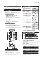
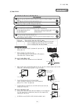
A remote control can control plural indoor units (up to 16)
In above setting, all plural indoor units will operate under same mode and temperature setting.
②
Connect all indoor units with 2 cores remote control line for group control.
③
Use the function of manual address setting to set the indoor and outdoor address number.
○
Do not forget to set the number for the outdoor units.
④
As shown in the following figure, the remote control can be used to control multiple outdoor
units.
⑤
One remote control is able to perform group control for multiple units (maximum 16 units).
○
Use the rotary SW1 and SW2 provided on the indoor unit PCB (Printed circuit board) to set unique remote control
communication address avoiding duplication.
Outdoor unit
No.01
Outdoor unit
No.02
Indoor unit
Indoor unit
Outdoor No.01
Indoor No.01
Indoor unit
Indoor unit
Indoor unit
Indoor unit
Remote control
Indoor unit
Remote control
SW1” Master”
Remote control
SW1” Slave”
Switch Setting Contents
Master
Slave
Slave remote
control
Wired remote control: SW1
Wireless kit: SW1-2
Master remote
control
Outdoor No.02
Indoor No.04
Outdoor No.01
Indoor No.02
Outdoor No.02
Indoor No.05
Outdoor No.01
Indoor No.03
Outdoor No.02
Indoor No.06
●
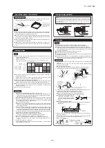
Do not install it on the following places.
(1) Place exposed to direct sunlight
(4) Hot surface or cold surface enough to generate condensation
(2) Places near heat devices
(5) Place exposed to oil mist or steam directly.
(3) High humidity places
(6) Uneven surface
③
Remote Control, Wiring and functions
①
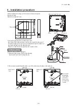
Install remote control referring to the attached manual.
②
Wiring of remote control should use 0.3mm
2
x2 cores wires or cables.
The insulation thickness is 1mm or more. (on-site configuration)
③
Maximum prolongation of remote control wiring is 600 m.
If the prolongation is over 100m, change to the size below.
But, wiring in the remote control case should be under 0.5mm
2
. Change the wire size outside of the case
according to wire connecting. Waterproof treatment is necessary at the wire connecting section. Be careful about
contact failure.
100-200m ...................0.5mm
2
×2 cores
Under 300m................0.75mm
2
× 2 cores
Under 400m................1.25mm
2
× 2 cores
Under 500m................2.0mm
2
× 2 cores
④
Avoid using multi-core cables to prevent malfunction.
⑤
Keep remote control line away from earth (frame or any metal of building).
⑥
Make sure to connect remote control line to the remote control and terminal block of
indoor unit. (No polarity)
Remote control line
(No polarity)
Remote control line
(No polarity)
Installation and wiring of remote control
Control plural indoor units by a single remote control
A maximum of two remote control units can be connected to one indoor unit (or one group of
indoor units.)
Latest "function setting" is superior than previous one.
Acceptable combination is "two (2) wired remote controls", "one (1) wired remote control and
one (1) wireless kit" or "two (2) wireless kits".
Set one to “Master” and the other to “Slave”.
Note:The setting "Remote control unit sensor enabled" is only selectable with the master
remote control unit in the position where you want to check room temperature.
Master/slave setting when more than one remote control unit are used
③④
Operation and confirmation from remote control
⑤
Function of CnT connector of indoor printed circuit board
●
X
R1-4
are DC 12 V relays. (Equivalent to Omron’s LY2F)
●
X
R5
is a DC 12 V, 24 V or 100 V relay. (Equivalent to Omron’s MY2F)
●
Maker and model of CnT connector (Site side)
Connector : Molex 5264-06
Terminal : Molex 5263T
●
CnTA connector is used on FDT, or other. <Check with the specifications.> (Site side) Maker
and model
Connector : J.S.T. Mfg. XAP02V-1-E
Terminal : J.S.T. Mfg. SXA-01T-P0.6
●
Output 1 – 4 and input1/2 can be selected/set as required from following items.
Factory default is set as shown below.
1
2
1
2
CNT
(Blue/6P)
+12
CNTA
(Blue/2P)
+12
Indoor PCB
X
R1
X
R1
X
R2
X
R3
X
R4
X
R2
X
R3
X
R4
X
R5
Common
Output 1
Output 2
Output 3
Output 4
Remote ON/OFF switch
or timer contactor
AC100V/1200V
DC12V
DC24V
Input 1
X
R6
AC100V/1200V
DC12V
DC24V
Input 2
Note (1) 0.3 mm
2
× 2 m
Note (1) 0.3 mm
2
× 2 m
Note (1) To be no longer than 2 m.
0.75mm
2
× 0.2 m
Butt-connecting contactor
Red
Black
Yellow
Blue
Brown
Orange
Remote ON-OFF/monitor kit
(Applicable range: 0.75 – 1.25 mm
2
)
X
R5
X
R6
White
Black
Yellow
Blue
Brown
Orange
Orange
●
For the setting method, refer to the technical data.
Output
Input
Factory default setting
①
②
③
④
⑤
⑥
⑦
⑧
RUN/STOP
RUN permit prohibition
Emergency stop
Cooling/Heating
Setting temp. shift
Compulsory thermostat OFF
Temporary stop
Silent mode
CnT-2
CnT-3
CnT-4
CnT-5
CnT-6
CnTA
RUN output
Heating output
Compressor ON output
Inspection (error) output
RUN/STOP
RUN/STOP
Output 1
Output 2
Output 3
Output 4
Input 1
Input 2
①
②
③
④
⑤
⑥
⑦
⑧
⑨
⑩
⑪
⑫
⑬
RUN output
Heating output
Compressor ON output
Inspection (error) output
Cooling output
Fan ON output 1
Fan ON output 2
Fan ON output 3
Defrost/oil return output
Ventilation output
Heater output
Free cleaning output
Indoor overload error output
1
2
3
4
5
6
1
2
3
4
5
6
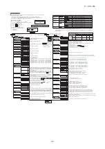
No.
Item
Operation from the eco touch remote
control (RC-EX3)
Operation from the standard remote control
(RC-E4, RC-E5)
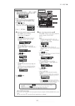
1 Check the number
of units connected
in the multi remote
control system.
[Menu]
⇒
[Service setting]
⇒
[Service & Maintenance]
⇒
[Service password]
⇒
[IU address]
①
Press the
AIR CON NO.
CHECK
TEST
TEST
button to display
the IU address.
②
Press the
AIR CON NO.
CHECK
TEST
TEST
or
AIR CON NO.
CHECK
TEST
TEST
button and check
addresses of connected indoor units one
by one.
2 Check if each unit is
connected properly
in the remote
control system.
[Menu]
⇒
[Service setting]
⇒
[Service & Maintenance]
⇒
[Service password]
⇒
[IU address]
⇒
[Check run mode]
①
Press the
AIR CON NO.
CHECK
TEST
TEST
button to display
the IU address.
②
Press the
AIR CON NO.
CHECK
TEST
TEST
or
AIR CON NO.
CHECK
TEST
TEST
button and select one
of IU addresses.
③
Press the
AIR CON NO.
CHECK
TEST
TEST
(MODE) button. The unit
starts to blow air.
3 Setting main/sub
remote controls
[Menu]
⇒
[Service setting]
⇒
[R/C function settings]
⇒
[Service password]
⇒
[Main/Sub of R/C]
Set SW1 to “Sub” for the sub remote control
unit.
4 Checking operation
data
[Menu]
⇒
[Service setting]
⇒
[Service & Maintenance]
⇒
[Service password]
⇒
[Operation data]
Press the
AIR CON NO.
CHECK
TEST
TEST
button.
⇒
“
AIR CON NO.
CHECK
TEST
TEST
”
is displayed.
⇒
Press the
AIR CON NO.
CHECK
TEST
TEST
(SET) button.
⇒
“
AIR CON NO.
CHECK
TEST
TEST
” is displayed.
⇒
Select one
of addresses for connected indoor units
by pressing the
AIR CON NO.
CHECK
TEST
TEST
or
AIR CON NO.
CHECK
TEST
TEST
button.
⇒
Press
the
AIR CON NO.
CHECK
TEST
TEST
(SET) button.
⇒
“
AIR CON NO.
CHECK
TEST
TEST
” is
displayed.
⇒
Select data by pressing the
AIR CON NO.
CHECK
TEST
TEST
or
AIR CON NO.
CHECK
TEST
TEST
button.
5 Checking inspection
display
[Menu]
⇒
[Service setting]
⇒
[Service & Maintenance]
⇒
[Service password]
⇒
[Error display]
Press the
AIR CON NO.
CHECK
TEST
TEST
button.
⇒
“
AIR CON NO.
CHECK
TEST
TEST
” is
displayed.
⇒
Press the
AIR CON NO.
CHECK
TEST
TEST
button.
⇒
“
AIR CON NO.
CHECK
TEST
TEST
” is displayed.
⇒
Press
the
AIR CON NO.
CHECK
TEST
TEST
(SET) button.
⇒
“
AIR CON NO.
CHECK
TEST
TEST
” is
displayed.
⇒
Data is displayed.
6 Cooling test run
from remote control
[Menu]
⇒
[Service setting]
⇒
[Installation settings]
⇒
[Service password]
⇒
[Test run]
⇒
[Cooling test run]
⇒
[Start]
①
Start the system by pressing the
AIR CON NO.
CHECK
TEST
TEST
button.
②
Select “
AIR CON NO.
CHECK
TEST
TEST
(Cool)” with the
AIR CON NO.
CHECK
TEST
TEST
(MODE)
button.
③
Press the
AIR CON NO.
CHECK
TEST
TEST
button for 3 seconds or
longer. The screen display will switch to
“
AIR CON NO.
CHECK
TEST
TEST
”.
④
Pressing the
AIR CON NO.
CHECK
TEST
TEST
(SET) button, while the
“
AIR CON NO.
CHECK
TEST
TEST
” is displayed, starts the
cooling test run. The screen display will
switch to “
AIR CON NO.
CHECK
TEST
TEST
”.
7 Trial operation of
drain pump from
remote control
[Menu]
⇒
[Service setting]
⇒
[Installation settings]
⇒
[Service password]
⇒
[Test run]
⇒
[Drain pump test run]
⇒
[Run]
①
Start the system by pressing the
AIR CON NO.
CHECK
TEST
TEST
button. The display will change
to “
AIR CON NO.
CHECK
TEST
TEST
”.
②
Press the
AIR CON NO.
CHECK
TEST
TEST
button once to display
“
AIR CON NO.
CHECK
TEST
TEST
”.
③
Pressing the
AIR CON NO.
CHECK
TEST
TEST
(SET) button starts the
drain pump operation. The display will
show “
AIR CON NO.
CHECK
TEST
TEST
”.
The menu configuration may vary depending on models of the remote control. If the model of your remote
control is different, refer to the installation manual attached to the remote control.

