background image

– 

44

 –

 '17 • KX-T-254

Press         or         button.

Make sure which do you want to set, "     FUNCTION     " 
(remote control function) or "I/U FUNCTION     " (indoor 
unit function).

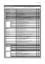
Note 1: The initial setting marked “     ” is decided by connected indoor and outdoor unit, and is automatically defined as following table.

Function No.
Remote control 

function02
Remote control 

function06
Remote control

function07
Remote control 

function13

Remote control 

function15

Default

Model

Indoor unit with only one of air flow setting
Heat pump unit

Exclusive cooling unit

"Auto-RUN" mode selectable indoor unit.
Indoor unit without "Auto-RUN" mode
Indoor unit with two or three step of air flow setting
Indoor unit with only one of air flow setting
Indoor unit with automatically swing louver
Indoor unit without automatically swing louver
Indoor unit with three step of air flow setting
Indoor unit with two step of air flow setting

Item

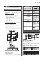
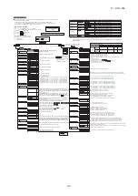
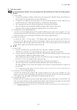
[Flow of function setting]

Note 3: As for plural indoor unit, set indoor functions to each master and slave indoor unit. 

But only master indoor unit is received the setting change of indoor unit function “05 EXTERNAL INPUT” and “06 PERMISSION /

PROHIBISHION”.

Indoor unit No. are indicated only when 
plural indoor units are connected.

01

02

Validate setting of ESP:External Static Pressure

Invalidate setting of ESP

Automatical operation is impossible

Temperature setting button is not working

02

03

03

04

04

05

05

06

06

07

07

08

09

08

10

09

11

10

12

11

13

12

13

14

14

15

16

15

17

18

19

Consult the technical data etc. for each control details

Finalize : Press “             ” (SET) button.
Reset

: Press “             ” (RESET) button.

Select : Press                 button.
End

: Press  ON/OFF  button.

It is possible to finish above setting on the way, 
and unfinished change of setting is unavailable.
“      ” : Initial settings
“      ” : Automatic criterion

How to set function

2.

1.

3.

4.

5.

It is possible to finish by pressing ON/OFF  button on the way, but unfinished change of setting is 

unavailable.
During setting, if you press              (RESET) button, you return to the previous screen.
Setting is memorized in the control and it is saved independently of power failure.

Permission/prohibition control of operation will be valid.

Record and keep the

setting

The functional setting

Stop air-conditioner and press

          (SET) +           (MODE) buttons

at the same time for over three seconds.

Function

setting

Function

setting

Mode button is not working

On/Off button is not working

Fan speed button is not working

Louver button is not working

Timer button is not working

Remote thermistor is not working.
Remote thermistor is working.
Remote thermistor is working, and to be set for pro3.0˚C increase in temperature.
Remote thermistor is working, and to be set for pro2.0˚C increase in temperature.
Remote thermistor is working, and to be set for pro1.0˚C increase in temperature.
Remote thermistor is working, and to be set for producing -1.0˚C increase in temperature.
Remote thermistor is working, and to be set for producing -2.0˚C increase in temperature.
Remote thermistor is working, and to be set for producing -3.0˚C increase in temperature.

If you change the range of set temperature, the indication of set temperature 

will vary following the control.

If you change the range of set temperature, the indication of set temperature

will not vary following the control, and keep the set temperature.

If you change the remote controller function "14                        ", 

you must change the indoor function "04                      " accordingly. 

You can select the louver stop position in the four.

The louver can stop at any position.

In normal working indication, indoor unit temperature is indicated instead of airflow.
(Only the master remote control can be indicated.)

Heating preparation indication should not be indicated.

Temperature indication is by degree C
Temperature indication is by degree F

To set other indoor unit, press

AIR CON No.

  button, which 

allows you to go back to the indoor 
unit selection screen 
(for example: I/U 000     ).

ON/OFF  button

(finished)

The filter sign is indicated after running for 180 hours.
The filter sign is indicated after running for 600 hours.
The filter sign is indicated after running for 1000 hours.
The filter sign is indicated after running for 1000 hours, then the indoor unit will be stopped by 
compulsion after 24 hours.
If you change the indoor function "04                           ",
you must change the remote control function "14                         " accordingly. 
You can select the louver stop position in the four.
The louver can stop at any position.

With the VRF series, it is used to stop all indoor units connected with the same outdoor unit immediately.
When stop signal is inputed from remote on-off terminal "CNT-6", all indoor units are stopped immediately. 

To be reset for pro3.0˚C increase in temperature during heating.
To be reset for pro2.0˚C increase in temperature during heating.
To be reset for pro1.0˚C increase in temperature during heating.

To be reset pro2.0˚C increase in return air temperature of indoor unit.
To be reset pro1.5˚C increase in return air temperature of indoor unit.
To be reset pro1.0˚C increase in return air temperature of indoor unit.

To be reset producing -1.0˚C increase in return air temperature of indoor unit.
To be reset producing -1.5˚C increase in return air temperature of indoor unit.
To be reset producing -2.0˚C increase in return air temperature of indoor unit.

When heating thermostat is OFF, fan speed is low speed.
When heating thermostat is OFF, fan speed is set speed.

When heating thermostat is OFF, fan speed is operated intermittently.
When heating thermostat is OFF, the fan is stopped.
When the remote thermistor is working, "FAN OFF" is set automatically.
Do not set "FAN OFF" when the indoor unit's thermistor is working.

Drain pump is run during cooling and dry.
Drain pump is run during cooling, dry and heating.
Drain pump is run during cooling, dry, heating and fan.
Drain pump is run during cooling, dry and fan.

After cooling is stopped is OFF, the fan does not perform extra operation.
After cooling is stopped is OFF, the fan perform extra operation for half an hour.
After cooling is stopped is OFF, the fan perform extra operation for an hour.
After cooling is stopped is OFF, the fan perform extra operation for six hours.

After heating is stopped or heating thermostat is OFF, the fan does not perform extra operation.
After heating is stopped or heating thermostat is OFF,the fan perform extra operation for half an hour.
After heating is stopped or heating thermostat is OFF,the fan perform extra operation for two hours.
After heating is stopped or heating thermostat is OFF, the fan perform extra operation for six hours.

During heating is stopped or heating thermostat is OFF, the fan perform intermittent operation for five minutes 
with low fan speed after twenty minutes' OFF.
During heating is stopped or heating thermostat is OFF, the fan perform intermittent operation for five minutes 
with low fan speed after five minutes' OFF.

Connected “OA Processing” type indoor unit, and is automatically defined.

Working only with the Single split series.
To control frost prevention, the indoor fan tap is raised. 

Change of indoor heat exchanger temperature to start frost prevention control.

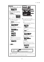
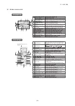
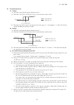
How to check the current setting

When you select  from "No. and funcion" and press set button by the previous operation,  the "Setting" displayed first is the current
setting.
(But, if you select "ALL UNIT      ", the setting of the lowest number indoor unit is displayed.)

Stop air-conditioner and press              (SET)              (MODE) 
buttons at the same time for over three seconds, and the 
"FUNCTION SET      " will be displayed.

Press              (SET) button.

Selecct "     FUNCTION      "  (remote control function) or "I/U 
FUNCTION     " (indoor unit function).

Operation message
Function description:      , 
setting description:

Function No.

Fixing button

Finishing button

7

2

1

6

Starting button

Previous screen button

Indoor unit selection button

Start

: Stop air-conditioner and press “             ” (SET) and
  “             ” (MODE) buttons at the same time for over three seconds.

)

n

o

it

c

n

u

ti

n

u

 r

o

o

d

n

I(

)

n

o

it

c

n

u

l

o

rt

n

o

c


e

t

o

m

e

R

(

In case of Single split series, by connecting ventilation device to CNT of the 

indoor printed circuit board (in case of VRF series, by connecting it to CND of the 

indoor printed circuit board),  the operation of ventilation device is linked with the 

operation of indoor unit.

In case of Single split series, by connecting ventilation device to CNT of the indoor printed 

circuit board (in case of VRF series, by connecting it to CND of the indoor printed circuit 

board),  you can operate /stop the ventilation device independently by              (VENT) button.

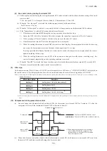
Press              (SET) button.

6.

"DATA LOADING" (Indication with blinking)

Display is changed to "01                       ".

7.

"DATA LOADING" (Blinking for 2 to 23 seconds to read the data)

(1)

(2)

(3)

Press              (SET) button.

On the occasion of remote control function selection

On the occasion of indoor unit function selection

Press         or         button.
"No. and function"are indicated by turns on the remote 
control function table, then you can select from them.
(For example)

Press         or         button.
Select the setting.

Press         or         button.
Select the setting.

The current setting of selected function is indicated.
(for example) "AUTO RUN ON"       If "02 AUTO RUN SET" is 
selected

Press              (SET) button.

Press              (SET) button.

Press         or         button.

Press         or         button.

Select the number of the indoor unit you are to set
If you select "ALL UNIT      ", you can set the same setting with 
all unites.

Press              (SET) 
"SET COMPLETE" will be indicated, and the setting will be 
completed.
Then after "No. and function" indication returns, Set as the 
same procedure if you want to set continuously ,and if to 
finish, go to 7.

Press   ON/OFF   button.

Setting is finished.

Indication is changed to "02 FAN SPEED SET".
Go to      .

[Note]

If plural indoor units are connected to a remote control, 
the indication is "I/U 000" (blinking)       The lowest number of 
the indoor unit connected is indicated.

"No. and function" are indicated by turns on the indoor unit function 
table, then you can select from them.
(For example)

The current setting of selected function is indicated.
(For example) "STANDARD"       If "02 FAN SPEED SET" is 
selected.

Press              (SET) button.

"SET COMPLETE" will be indicated, and the setting will be 
completed.
Then after "No. and function" indication returns, set as the same 
procedure if you want to set continuously , and if to finish, go to 7.

Setting

Function No.
Function

When plural indoor units are connected to a remote control, 
press the   AIRCON NO.  button, which allows you to go back to 
the indoor unit selection screen. (example "I/U 000     ")

The initial function setting for typical using is performed automatically by the indoor unit connected, when remote 
control and indoor unit are connected.
As long as they are used in a typical manner, there wiil be no need to change the initial settings.
If you would like to change the initial setting marked “      ”, set your desired setting as for the selected item.
The procedure of functional setting is shown as the following diagram.

Function No.
Function

Setting

If you input signal into CnT of the indoor printed circuit board from external, the 

indoor unit will be operated independently according to the input from external.

If you input into CNT of the indoor printed circuit board from external, all units which 

connect to the same remote control are operated according to the input from external.

16

17

Air flow of fan is fixed at one speed.

Air flow of fan becomes the three speed of         -        -        or         -        -        -        .

Air flow of fan becomes the two speed of         -        .

Air flow of fan becomes the two speed of         -        .

Note2: Fan setting of "HIGH SPEED"

Initial function setting of some indoor unit is "HIGH SPEED".

UH - Hi 

UH - Me

UH - Hi - Me 

STANDARD

HIGH

SPEED1, 2

FAN

SPEED

SET

Hi - Lo

Hi - Me

-

-

-

-

-

-

-

Hi - Me - Lo

UH - UH - Hi - Me

UH - Hi - Me - Lo

Indoor unit air flow setting

Fan tap

PJA012D730

Summary of Contents for FDT112KXZE1

Page 1: ...Z series refer to the No 14 KX T 223 No 15 KX T 227 and Note No 16 KX DB 225D INDOOR UNIT Ceiling cassete 4way type KXZ series VRF INVERTER MULTI SYSTEM AIR CONDITIONERS FDT28KXZE1 FDT36KXZE1 FDT45KXZE1 FDT56KXZE1 FDT71KXZE1 FDT90KXZE1 FDT112KXZE1 FDT140KXZE1 FDT160KXZE1 ...

Page 2: ... wired remote control 49 1 Model RC EX3 34 2 Model RC E5 41 6 CAPACITY TABLES 8 3 Operation control function by the indoor control 52 9 SYSTEM TROUBLESHOOTING PROCEDURE 70 9 1 Basics of troubleshooting 70 9 2 Contents of troubleshooting 71 9 3 Instruction of how to replace PCB 104 2 11 10 15 9 4 Indoor PCB setting 105 10 OPTION PARTS 10 1 Wireless kit RCN T 5AW E2 106 114 10 2 Simple wired remote ...

Page 3: ...ide air intake Possible Possible Possible Possible Possible Air filter Q ty Pocket plastic net 1 Washable Pocket plastic net 1 Washable Pocket plastic net 1 Washable Pocket plastic net 1 Washable Pocket plastic net 1 Washable Shock vibration absorber Rubber sleeve for fan motor Rubber sleeve for fan motor Rubber sleeve for fan motor Rubber sleeve for fan motor Rubber sleeve for fan motor Insulatio...

Page 4: ...take Possible Possible Possible Possible Air filter Q ty Pocket plastic net 1 Washable Pocket plastic net 1 Washable Pocket plastic net 1 Washable Pocket plastic net 1 Washable Shock vibration absorber Rubber sleeve for fan motor Rubber sleeve for fan motor Rubber sleeve for fan motor Rubber sleeve for fan motor Insulation noise heat Polyurethane form Polyurethane form Polyurethane form Polyuretha...

Page 5: ...ne Holes for tapping screws Holes for tapping screws Decorative panel Air supply Air return grille Suspension bolts pitch P1 Ceiling hole size box Control Suspension bolts pitch P2 Accessory Installed on site suspension bolt Hanger plate for Control box Hole Hole Holes for tapping screws Hole H1 H2 φ9 52 3 8 Fl a re φ15 88 5 8 Fl a re φ12 7 1 2 Fl a re φ9 52 3 8 Fl a re Model 28 36 45 56 71 Anti d...

Page 6: ... units when installing more than one Holes for tapping screws Holes for tapping screws Decorative panel Air supply Air return grille Suspension bolts pitch P1 Ceiling hole size box Control Suspension bolts pitch P2 Accessory Installed on site suspension bolt Hanger plate for Control box Hole Hole Holes for tapping screws Hole H1 H2 Anti draft function 1 Notes 1 The model name label is attached to ...

Page 7: ...pace R C cable 0 3mm2 2 cores Adapted to RoHS directive Exterior appearance Munsell color Pearl white N8 5 near equivalent Installation space R C 2 2 core Adapted to RoHS directive Exterior appearance Munsell color Pearl white N8 5 near equivalent 2 Remote control Option parts ...

Page 8: ...res 2 0mm2 2 cores Under 300m Under 400m Under 600m Upper part Lower part Lower case Sheath Upper cace Board Wiring Upper Lower X Y Sheath Upper cace Board Wiring Upper Lower Y X Tighten the screws after cutting off the thin part of screw mounting part Embedded mounting The peeling off length of sheath The peeling off length of sheath In case of pulling out from upper left In case of pulling out f...

Page 9: ... 8 17 KX T 254 b Wireless remote control RCN E2 Unit mm 60 24 167 ...

Page 10: ...acity setting SW6 Terminal block Power source TB1 TB2 Steppi n g motor For el e ctroni c expansi o n val v e SM SW1 SW2 Indoor unit address tens place Indoor unit address ones place SW3 SW4 Automatic adjustment Fixed previous SW5 1 SW5 2 SW7 1 Thi A Thi R1 2 3 Thc Outdoor unit address tens place Outdoor unit address ones place Indoor unit address hundreds place Terminal block Signal line Thermisto...

Page 11: ...id octave band frequency Hz Sound pressure level dB Standard 2 10 5 Pa Noise level 33dB A at P Hi Noise level 34dB A at P Hi Noise level 35dB A at P Hi Noise level 38dB A at P Hi Noise level 49dB A at P Hi Noise level 47dB A at P Hi Noise level 49dB A at P Hi Sound pressure level dB Standard 2 10 5 Pa Sound pressure level dB Standard 2 10 5 Pa Sound pressure level dB Standard 2 10 5 Pa Sound press...

Page 12: ...distribution at the center of air outlet within the published conditions In the actual installation they may differ from the typical figures under the influence of air temperature conditions ceiling height operation conditions and obstacles A ISD16448 Models FDT28KXZE1 36KXZE1 45KXZE1 P Hi P Hi Temperature distribution Velocity distribution Temperature distribution Velocity distribution P Hi ...

Page 13: ... 12 17 KX T 254 Model FDT56KXZE1 P Hi P Hi Temperature distribution Velocity distribution Temperature distribution Velocity distribution A ISD16448 P Hi ...

Page 14: ... 13 17 KX T 254 Model FDT71KXZE1 P Hi P Hi Temperature distribution Velocity distribution Temperature distribution Velocity distribution A ISD16448 P Hi ...

Page 15: ... 14 17 KX T 254 Models FDT90KXZE1 112KXZE1 140KXZE1 160KXZE1 P Hi P Hi Temperature distribution Velocity distribution Temperature distribution Velocity distribution A ISD16448 P Hi ...

Page 16: ... DB WB 16 DB 18 DB 20 DB 22 DB 24 DB 10 0 00 2 02 1 94 2 41 2 31 2 61 2 42 2 77 2 43 3 11 2 64 3 23 2 59 19 8 20 1 61 1 61 1 61 1 61 1 61 12 0 00 2 02 1 94 2 41 2 31 2 61 2 42 2 77 2 43 3 10 2 64 3 21 2 59 17 8 18 1 71 1 71 1 71 1 71 1 71 14 0 00 2 02 1 94 2 41 2 31 2 61 2 42 2 77 2 43 3 09 2 64 3 20 2 58 15 7 16 1 81 1 81 1 81 1 81 1 81 16 0 00 2 02 1 94 2 41 2 31 2 61 2 42 2 76 2 43 3 07 2 63 3 ...

Page 17: ...WB 16 WB 18 WB 19 WB 20 WB 22 WB 24 WB DB WB 16 DB 18 DB 20 DB 22 DB 24 DB 10 0 00 2 50 2 40 2 99 2 72 3 23 2 76 3 44 2 79 3 85 3 03 4 00 2 97 19 8 20 1 97 1 97 1 97 1 97 1 97 12 0 00 2 50 2 40 2 99 2 72 3 23 2 76 3 44 2 79 3 84 3 02 3 98 2 95 17 8 18 2 10 2 10 2 10 2 10 2 10 14 0 00 2 50 2 40 2 99 2 72 3 23 2 76 3 43 2 79 3 83 3 02 3 97 2 95 15 7 16 2 23 2 23 2 23 2 23 2 23 16 0 00 2 50 2 40 2 99...

Page 18: ... WB 18 WB 19 WB 20 WB 22 WB 24 WB DB WB 16 DB 18 DB 20 DB 22 DB 24 DB 10 0 00 3 17 2 82 3 79 3 19 4 10 3 25 4 36 3 28 4 89 3 56 5 08 3 48 19 8 20 2 51 2 51 2 51 2 51 2 51 12 0 00 3 17 2 82 3 79 3 19 4 10 3 25 4 36 3 28 4 87 3 55 5 05 3 46 17 8 18 2 67 2 67 2 67 2 67 2 67 14 0 00 3 17 2 82 3 79 3 19 4 10 3 25 4 35 3 28 4 85 3 54 5 03 3 46 15 7 16 2 83 2 83 2 83 2 83 2 83 16 0 00 3 17 2 82 3 79 3 19...

Page 19: ... WB 19 WB 20 WB 22 WB 24 WB DB WB 16 DB 18 DB 20 DB 22 DB 24 DB 10 0 00 3 89 3 20 4 64 3 61 5 02 3 68 5 35 3 75 5 99 4 05 6 22 3 95 19 8 20 2 95 2 95 2 95 2 95 2 95 12 0 00 3 89 3 20 4 64 3 61 5 02 3 68 5 34 3 74 5 97 4 04 6 19 3 94 17 8 18 3 14 3 14 3 14 3 14 3 14 14 0 00 3 89 3 20 4 64 3 61 5 02 3 68 5 33 3 74 5 94 4 03 6 16 3 92 15 7 16 3 33 3 33 3 33 3 33 3 33 16 0 00 3 89 3 20 4 64 3 61 5 02 ...

Page 20: ...0 WB 22 WB 24 WB DB WB 16 DB 18 DB 20 DB 22 DB 24 DB 10 0 00 4 42 3 60 5 28 4 07 5 71 4 16 6 08 4 22 6 81 4 56 7 07 4 45 19 8 20 3 43 3 43 3 43 3 43 3 43 12 0 00 4 42 3 60 5 28 4 07 5 71 4 16 6 07 4 22 6 78 4 55 7 04 4 43 17 8 18 3 65 3 65 3 65 3 65 3 65 14 0 00 4 42 3 60 5 28 4 07 5 71 4 16 6 06 4 21 6 76 4 54 7 01 4 42 15 7 16 3 87 3 87 3 87 3 87 3 87 16 0 00 4 42 3 60 5 28 4 07 5 71 4 16 6 05 4...

Page 21: ...r flow 14 WB 16 WB 18 WB 19 WB 20 WB 22 WB 24 WB DB WB 16 DB 18 DB 20 DB 22 DB 24 DB 10 0 00 6 07 5 31 7 26 6 00 7 85 6 11 8 36 6 19 9 36 6 69 9 72 6 54 19 8 20 4 66 4 66 4 66 4 66 4 66 12 0 00 6 07 5 31 7 26 6 00 7 85 6 11 8 35 6 18 9 33 6 68 9 68 6 51 17 8 18 4 96 4 96 4 96 4 96 4 96 14 0 00 6 07 5 31 7 26 6 00 7 85 6 11 8 33 6 18 9 29 6 67 9 64 6 50 15 7 16 5 26 5 26 5 26 5 26 5 26 16 0 00 6 07...

Page 22: ...or air temperature Outdoor 21 DB 23 DB 26 DB 27 DB 28 DB 31 DB 33 DB Air flow 14 WB 16 WB 18 WB 19 WB 20 WB 22 WB 24 WB DB WB 16 DB 18 DB 20 DB 22 DB 24 DB 10 0 00 7 63 6 17 9 12 6 97 9 87 7 14 10 50 7 24 11 76 7 79 12 21 7 59 19 8 20 5 89 5 89 5 89 5 89 5 89 12 0 00 7 63 6 17 9 12 6 97 9 87 7 14 10 49 7 24 11 72 7 77 12 16 7 57 17 8 18 6 27 6 27 6 27 6 27 6 27 14 0 00 7 63 6 17 9 12 6 97 9 87 7 1...

Page 23: ...8 38 11 41 8 25 11 66 8 50 11 92 8 25 Indoor air temperature Outdoor 21 DB 23 DB 26 DB 27 DB 28 DB 31 DB 33 DB Air flow 14 WB 16 WB 18 WB 19 WB 20 WB 22 WB 24 WB DB WB 16 DB 18 DB 20 DB 22 DB 24 DB 10 0 00 9 38 7 20 11 21 8 16 12 13 8 37 12 90 8 50 14 45 9 16 15 01 8 91 19 8 20 7 15 7 15 7 15 7 15 7 15 12 0 00 9 38 7 20 11 21 8 16 12 13 8 37 12 88 8 49 14 40 9 14 14 94 8 89 17 8 18 7 61 7 61 7 61 ...

Page 24: ...12 86 9 20 13 00 9 05 13 28 9 30 13 59 9 01 Indoor air temperature Outdoor 21 DB 23 DB 26 DB 27 DB 28 DB 31 DB 33 DB Air flow 14 WB 16 WB 18 WB 19 WB 20 WB 22 WB 24 WB DB WB 16 DB 18 DB 20 DB 22 DB 24 DB 10 0 00 11 02 8 15 13 17 9 24 14 25 9 50 15 16 9 66 16 98 10 41 17 63 10 11 19 8 20 7 56 7 56 7 56 7 56 7 56 12 0 00 11 02 8 15 13 17 9 24 14 25 9 50 15 14 9 65 16 92 10 39 17 55 10 08 17 8 18 8 0...

Page 25: ...cause unit failure and fire Do not install the indoor unit near the location where there is possibility of flammable gas leakages If the gas leaks and gathers around the unit it could cause fire Do not install and use the unit where corrosive gas such as sulfurous acid gas etc or flammable gas such as thinner petroleum etc may be generated or accumulated or volatile flammable substances are handle...

Page 26: ...or 2 way according to the shape of the room and installation position 1 way is not available If it is necessary to change the number of air supply port prepare the covering materials sold as accessory Instruct the user not to use low fan speed when 2way or 3way air supply is used Do not use 2way air supply port under high temperature and humidity environment Otherwise it could cause condensation a...

Page 27: ...68 82 100 120 mm 0 8 0 8 0 8 1 1 2 Protruding dimension Flare die 1 Remove the flare nut and blind flanges on the pipe of the indoor unit Makesuretoloosentheflarenutwithholdingthenutonpipesidewithaspannerandgivingtorquetothe nut with another spanner in order to avoid unexpected stress to the copper pipe and then remove them Gas may come out at this time but it is not abnormal Pay attention whether...

Page 28: ...V Part No SSA564A149AF Panel installation Install the panel on the indoor unit after electrical wiring work Refer to the attached manual for panel installation for details How to check the dirt of drain pan and cleanimg the inlet of the drain pump Maintenance The method of checking the dirt of drain pan It is possible to check dirt on the drain pan and drain pump inlet without removing the panel 1...

Page 29: ...ting Standard panel without the anti draft mechanism Anti draft panel with the anti draft mechanism Panel installation Indoor Unit Ceiling surface Level gauge Accessary of the indoor unit inserted into the unit Ceiling opening dimensions 10 4 0 Keep the distance between 10 14mm Exceeding the range of the distance may cause failure etc 1 Before installation 3 Removing the inlet grille Accessories F...

Page 30: ...ing work varies depending on the panel type Select the wiring work appropriate for the panel type The connection positions of the indoor unit are as shown below irrespective of the panel type For the Standard panel 1 Loosen 2 screws on the control box lid of the indoor unit and remove the lid by sliding it 2 Pass the flap motor wiring 20 wire through the hook of the control box and connect to CNJ1...

Page 31: ... unit address hundreds place SW6 1 4 Model capacity setting SW7 1 ON Operation check Drain motor test run OFF Normal operation Round crimp terminal Electric cable Electrical wiring work must be performed by an electrician an qualified by a local power provider These wiring specifications are determined on the assumption that the following instructions are observed Do not use cords other than coppe...

Page 32: ...R3 XR4 XR5 Common Output 1 Output 2 Output 3 Output 4 Remote ON OFF switch or timer contactor AC100V 1200V DC12V DC24V Input 1 XR6 AC100V 1200V DC12V DC24V Input 2 Note 1 0 3 mm2 2 m Note 1 0 3 mm2 2 m Note 1 To be no longer than 2 m 0 75mm2 0 2 m Butt connecting contactor Red Black Yellow Blue Brown Orange Remote ON OFF monitor kit Applicable range 0 75 1 25 mm2 XR5 XR6 White Black Yellow Blue Br...

Page 33: ...ting is done by the both factors of the set temp and outdoor air temp The set temp and fan speed can be set A 7 External Ventilation When the ventilator is combined On Off operation of the external ventilator can be done It is necessary to set from Menu Service setting R C function settings Ventilation setting If the Independent is selected for the ventilation setting the ventilator can be operate...

Page 34: ...B 3 IU settings Fan speed setting The fan speed for indoor units can be set B Filter sign The setting of filter sign display timer can be done from following patterns B Service password External input 1 The connect of control by external input 1 can be changed B External input 1 signal The type of external input 1 signal can be changed B External input 2 The connect of control by external input 2 ...

Page 35: ... source before starting electrical work Otherwise it could result in electric shocks break down or malfunction Do not modify the unit It could cause electric shocks fire or break down Be sure to turn OFF the power circuit breaker before repairing inspecting the unit Repairing inspecting the unit with the power circuit breaker turned ON could cause electric shocks or injury Please read this manual ...

Page 36: ...ectric shocks fire or break down Use the specified cables for wiring and connect them securely with care to protect electronic parts from external forces Improper connections or fixing could cause heat generation fire etc Seal the inlet hole for remote control cable with putty If dew water insect etc enters through the hole it could cause electric shocks fire or break down If dew or water enters th...

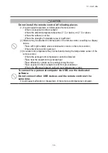
Page 37: ...ation occurs on the remote control Where the remote control gets wet 3 Accurate room temperature may not be detected using the temperature sensor of the remote control Where the average room temperature cannot be detected Place near the equipment to generate heat Place affected by outside air in opening closing the door Place exposed to direct sunlight or wind from air conditioner Where the differ...

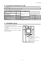
Page 38: ...ength is longer than 100 m the max size for wires used in the R C case is 0 5 mm2 Connect them to wires of larger size near the outside of R C When wires are connected take measures to prevent water etc from entering inside 200 m 0 5 mm2 x 2 cores 300m 0 75 mm2 x 2 cores 400m 1 25 mm2 x 2 cores 600m 2 0 mm2 x 2 cores Secure the installation space shown in the figure For the installation method emb...

Page 39: ...s Viewed from front 37 23 23 固定穴 18 3 83 5 120 19 120 37 23 23 19 120 Fixing holes 83 5 120 18 3 PCB side Viewed from rear 8 50 200 壁 電線管 ロ ッ クナッ ト スイ ッ チ ボ ッ クス パテで シール する こ と リ モコ ン配線 下ケース配線穴 ブッ シ ング センサー USB 端子 Wall Conduit Sensor USB port Terminal block Locknut Bushing Switch box Seal with putty R C cable When wires are passed through the bottom case fix the bottom case at 2 places on the swit...

Page 40: ...ke care not to pinch the sheath Tighten by hand 0 7 N m or less the wire connection If the wire is connected using an electric driver it may cause failure or deformation In case of exposing wiring When the wiring is taken out from the upper center or upper left of R C Cut out the thin wall sections on the cases for the size of wire Fix the bottom R C case on a flat surface with two wood screws In ...

Page 41: ...er lower flap control Left right flap control Ventilation setting Auto restart Auto temp setting Auto fan speed IU settings Service Maintenance IU address Next service date Operation data Error display Error history Display erase anomaly data Reset periodical check Saving IU settings Special settings Erase IU address CPU reset Restore of default setting Touch panel calibration Indoor unit capacity...

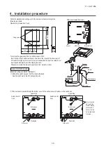
Page 42: ... of remote control lower case with a nipper or knife and grind burrs with a file etc Install the lower case to the flat wall with attached two wooden screws Connect the remote cont terminal block Connect the terminal of r with the terminal of indoo X and Y are no polarity Wiring route is as shown depending on the pulling The wiring inside the rem The sheath should be pe The peeling off length of P...

Page 43: ...rminal of indoor unit X Y X and Y are no polarity Wiring route is as shown in the right diagram depending on the pulling out direction The wiring inside the remote control case should be within 0 3mm2 recommended to 0 5mm2 The sheath should be peeled off inside the remote control case The peeling off length of each wire is as below Pulling out from upper left Pulling out from upper center X wiring...

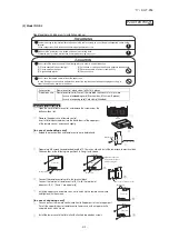
Page 44: ... for over three seconds The indication changes to FUNCTION SET 2 Press button once and change to the TEMP RANGE indication 3 Press SET button and enter the temperature range setting mode 4 Select UPPER LIMIT or LOWER LIMIT by using button 5 Press SET button to fix 6 When UPPER LIMIT is selected valid during heating Press SET button to fix Indication example UPPER 26 C Displayed for two seconds Aft...

Page 45: ...2 0 C increase in return air temperature of indoor unit To be reset producing 1 5 C increase in return air temperature of indoor unit To be reset producing 1 0 C increase in return air temperature of indoor unit To be reset producing 1 0 C increase in return air temperature of indoor unit To be reset producing 1 5 C increase in return air temperature of indoor unit To be reset producing 2 0 C incr...

Page 46: ...or unit function Operation message Function description setting description Function No Fixing button Finishing button 7 2 1 6 Starting button Previous screen button Indoor unit selection button Press SET button 6 DATA LOADING Indication with blinking Display is changed to 01 7 DATA LOADING Blinking for 2 to 23 seconds to read the data 1 2 3 Press SET button On the occasion of remote control funct...

Page 47: ...ce can be changed LCD With backlight A tap on the LCD lights the backlight The backlight turns off automatically if there is no operation for certain period of time Lighting period of the backlight lighting can be changed If the backlight is ON setting when the screen is tapped while the backlight is turned off the backlight only is turned on Operations with switches and are excluded USB port USB ...

Page 48: ... adjustment mode Cover AIR CON No button Display the indoor unit number connected to this remote control CHECK button This button is used at servicing TEST button This button is used during test operation Weekly timer display Displays the settings of the weekly timer Operation setting display area Displays setting temperature airflow volume operation mode and oparation message Operation check indi...

Page 49: ...is pressed once again it stops operating MODE button Every time this button is pressed displays switch as below AUTO COOL HEAT FAN DRY TEMP button Change the set temperature by pressing or button FAN SPEED button The fan speed is switched in the following order 1 speed 2 speed 3 speed 4 speed AUTO 1 speed U D button Used to determine the up down louver position L R button Used to determine the lef...

Page 50: ... CPU reset Reset CPU from the remote control as follows TOP screen Menu Service setting Service Maintenance Service password The selected screen is displayed The selected screen is displayed Service Maintenance 2 Special settings CPU reset Microcomputers of indoor unit and outdoor unit connected are reset State of restoration after power failure 3 Power failure compensation function Electric power...

Page 51: ... Indoor function items are saved in the memory of indoor unit g Weekly timer peak cut timer or silent mode timer settings h Remote control function setting Please check the I U Set clock first on the initializing screen set the timer Other thanA C is connected If the following a to c appear check and repair as follows Communication check screen This appears if communications cannot be established ...

Page 52: ...de the state of stop is memorized Although the timer mode is cancelled at the recovery from power failure the setting of weekly timer is changed to the holiday setting for all weekdays b Operation mode c d Room temperature setting e Louver auto swing stop However the stop position 4 position is cancelled so that it returns to Position 1 f Remote control function items which have been set with the ...

Page 53: ...ature shown at right Room temperature Setting temperature 3 3 Cooling operation Heating operation Room temperature detected with Thi A deg 59 56 Heating operation stopped cooling Heating OK Indoor heat exchanger temperature C b The following automatic controls are performed other than a above i Cooling or heating operation mode is judged according to the conditions of the Judgment based on Setting...

Page 54: ...tart Defrost Compressor 4 way valve Outdoor unit fan Indoor unit fan Drain pump 3 2 2 Thermostat ON Thermostat OFF 2 2 Notes 1 Operation Stop Turned ON OFF by the control other than the room temperature control 2 ON during the drain motor delay control 3 Drain pump ON setting may be selected with the indoor unit function setting of the wired remote control 3 Dehumidifying DRY operation Indoor ambi...

Page 55: ...er vi Weekly timer Set the ON or OFF timer for a week Up to 8 patterns can be set for a day The day off setting is provided for holidays and non business days Note 1 It is necessary to set the clock to use the weekly timer vii Combination of patterns which can be set for the timer operations Note 1 Allowed Not Sleep time Sleep time Set OFF timer by hour Weekly timer Set ON timer by hour Set OFF ti...

Page 56: ...erates with the set air flow volume regardless of the thermostat ON OFF 2 Once the fan motor is changed from OFF to ON during the thermostat ON the indoor fan motor is not turned OFF even if the heat exchanger thermistor detects lower than 25 C Note 1 When the defrost operation signal is received it complies with the fan control during defrost operation 3 Once the hot start is completed it will no...

Page 57: ...r control 1 Press the LOUVER button to operate the swing louver when the air conditioner is operating SWING is displayed for 3 seconds and then the swing louver moves up and down continuously 2 the swing louver at a position press one time the LOUVER button while the swing louver is moving so that four stop positions are displayed one after another per second When a desired stop position is displa...

Page 58: ... indoor fan stops 2 Indoor fan OFF is for 5 minutes After the 5 minutes the indoor fan is operated at ULo for 2 minutes In the meantime the louver is controlled at level 3 After operating at ULo for 2 minutes the indoor fan moves to the state of 1 above 4 If the thermostat is turned ON it moves to the hot start control 5 When the heating thermostat is turned OFF the remote control displays the tem...

Page 59: ...Stopped by remote control etc 1 1 Even when the thermostat of another indoor unit is turned ON after the compressor ON the thermostat is not turned OFF for 2 minutes after the compressor ON 1 OFF OFF 3 minutes delay Thermostat OFF in the condition of item 8 Compressor Indoor unit A Thermostat Indoor unit B Thermostat b When the oil return control has started while the thermostat is turned ON the t...

Page 60: ...ng the drain detection switch OFF releases the forced drain pump ON condition Normal state 1 2 Normal state Drain detection switch ON Stop 1 Indoor unit operation mode Control A Control B Compressor ON Compressor OFF Cooling Dry Heating Fan 2 Note 1 Including the stop from the cooling dehumidifying fan and heating and the anomalous stop 2 Including the Fan operation according to the mismatch of op...

Page 61: ...ndoor heat exchanger temperature has become as show below after reducing the compressor speed it is switched to the fan operation For the selection of indoor fan speed refer to item 2 10 1 0 Indoor heat exchanger temperature C Fan operation Cooling operation SRC40 60 FDC100 140 Model Symbol A 4 4 1 1 1 0 1 0 B C b Selection of indoor fan speed If it enters the frost prevention control during cooli...

Page 62: ... short circuit detection a Broken wire detection When the return air temperature thermistor detects 20 C or lower or the heat exchanger temperature thermistor detect 40 C or lower for 5 seconds continuously the compressor stops After a 3 minute delay the compressor restarts but if it is detected again within 60 minutes after the initial detection for 6 minutes continuously stops again the return a...

Page 63: ...f CnT Number CnTA Number the function of CnT Number supersedes that of CnTA Number 6 In case of CnT Number CnTA Number the function of CnTA Number supersedes that of CnT Number The Number above means in the table Blue 12V XR6 2 CnTA Operation stop level Operation stop pulse Operation permission prohibition Operation permission prohibitionpulse Cooling heating selection level Cooling heating select...

Page 64: ...imers When the indoor function setting of wired remote control for Operation permission prohibition is changed from Invalid Factory default to Valid following control becomes effective CnT CnTA XR5 Card key switch XR1 1 2 3 4 5 6 XR3 XR4 CnT Blue DC12V XR2 Option XR5 CnTA Blue DC12V XR6 1 2 Normal operation Factory default Operation permission prohibition mode Valid Local setting CnT 6 or CnTA ON ...

Page 65: ...l Operation permission prohibition zone Actual operation Remote control Remote control ON Remote control OFF Remote control ON Remote control ON Remote control OFF Remote control ON ON ON ON ON ON ON ON OFF OFF OFF OFF OFF OFF OFF ON ON OFF ON ON ON ON ON OFF OFF OFF OFF OFF OFF Operation Operation Operation Operation Stop Stop Stop Stop Stop In case of CnT operation permission prohibition level C...

Page 66: ...the OR judgment between CnT operation prohibition zone and CnTA operation prohibition zone Operation permission prohibition zone Operation permission Operation permission Operation permission 22 Selection of cooling heating external input function When External input 1or 2 setting Cooling heating is set by the indoor unit function from remote control the cooling or heating is selected with CnT 6 o...

Page 67: ...e priority order for combinations of CnT and CnTA refer to Page 62 External input selection Cooling heating selection External input method Level External input CnT or CnTA Cooling heating Cooling heating Competitive External input CnT or CnTA Cooling heating Cooling heating Competitive Pulse Operation OFF Cooling zone Cooling zone Heating zone Heating zone OFF ON ON Cooling Heating Heating Coolin...

Page 68: ...nit ii Specify the Main or Sub for the indoor units from the remote control b Change of operation modes from the remote control option control or other external device can be made for the master unit only It cannot be made for slave units c Operation mode of slave units is always same as that of the master unit d Any setting other than the operation mode can be made individually for the main and s...

Page 69: ...ensor becomes bigger than 3 C 34 The operation judgment is executed every 5 minutes RC EX3 only Setting temperature Ts is changed according to outdoor temperature This control is valid with cooling and heating mode Not auto mode a Operate 5 minutes forcedly b Setting temperature is adjusted every 10 minutes i Cooling mode Ts outdoor temperature offset value ii Heating mode Ts outdoor temperature o...

Page 70: ...The set temperature is adjusted according to the presence of people and their amount of activity detected by the infrared sensor ii Auto off control When no activity is deteced for 1 hour unit will go stand by mode Unit will re start operation automatically by activity detection during the stand by mode 38 Motion sensor control RC EX3 only The sensor determines the presence of people and the amoun...

Page 71: ...e related to any hardware parts SV main body coil capillary check valve sensor etc Is it a major component Compressor inverter PCB and outdoor DC fan motor Is it a failure of electrical component Error on indoor unit or outdoor unit Indoor unit Outdoor unit Is the remote control connected Was the power source reset after the error occurred Check and write down the momentary data retained in the re...

Page 72: ... return air temperature thermistor anomaly Thi A Thermistor wire breakage 93 E9 Drain trouble System error E10 Excessive number of indoor units more than 17 units by controlling one remote control Communication error E11 Address setting error of indoor units Address setting error E12 Address setting error by mixed setting method Address setting error E16 Indoor DC fan motor anomaly DC fan motor er...

Page 73: ...eating operation from remote control Note 1 Outdoor 35ºC Indoor 27ºCDB 19ºCWB It is normal This unit is designed to start in the soft start mode by detecting the compressor under dome temperature when it restart after power reset It is necessary to replace to higher capacity unit or to install additional unit Compressor refrigerant oil protective control at starting is activated For the contents o...

Page 74: ...on from remote control Note 1 Outdoor 7ºC Indoor 20ºCDB It is normal This unit is designed to start in the soft start mode by detecting the compressor under dome temperature when it restart after power reset It is necessary to replace to higher capacity unit or to install additional unit Compressor refrigerant oil protective control at starting is activated For the contents of control refer to the...

Page 75: ... Prevent the vibration from transmitting to wall and etc by fixing pipes on the wall tightly or wrapping rubber cushion around the pipe which goes through the hole in the wall or applying other appropriate means Strength of ceiling wall floor etc may be insufficient Review the installation place or apply reinforcement to increase the strength Check for leaning of installed unit or incorrect mounti...

Page 76: ...ularly during cooling or defrost operation in the heating mode It is normal The noise vibration occurs when the refrigerant starts or stops flowing It is normal When the defrost operation starts or stops during heating mode the refrigerant flow is reversed due to switching 4 way valve This causes a large change in pressure which produces a blowing sound It may also accompany the hissing sound as m...

Page 77: ...on of air nitrogen etc In such case it is necessary to recover refrigerant vacuum dry and recharge refrigerant Since there could be many causes of noise vibration the above may not cover all In such case check the conditions when where how the noise vibration occurs according to following check points and ask our consultation Indoor outdoor unit Cooling heating fan mode Startup stop during operati...

Page 78: ...nit side LM louver motor Is the louver operable with the remote control YES NO Does the louver operate at the power on YES NO YES NO Operate after waiting for more than 1 minute Repair wiring Indoor unit PCB anomaly Replace it Replace LM Normal Replace louver motor If errors persist even after replacing the louver motor replace the indoor unit PCB 2 Error detection method 3 Condition of error disp...

Page 79: ...d between CNP Is JX1 open None of actuator etc is short circuited Are fuses OK Is resistance between of CNW0 OK Is DC280V detected between CNM1 Is resistance to FM LM and etc OK Note 1 Check the fuse at the power source side 1 2 Outdoor noise filter PCB anomaly Replace it Wrong wiring or broken wires between outdoor and indoor units Indoor unit PCB anomaly Replace it Replace FM LM and etc Replace ...

Page 80: ...voltage between X and Y in the indoor terminal block exceed 15 VDC YES NO YES NO NO YES Does the voltage between X and Y in the indoor terminal block exceed 15 VDC Remove wire for the remote control Power source reset YES Correct Remote control wire breakage Replace remote control Malfunction by temporary noise Defective indoor unit PCB Replace Remote control wire breakage Replace remote control 2...

Page 81: ... page Replace noise filter PCB Connect wires correctly Indoor unit PCB anomaly Replace it Indoor outdoor unit control PCB anomaly Replace it Remote control anomaly Replace it Breakage of wires for remote control Replace it Correct the connecting wires between indoor and outdoor units Outdoor unit control PCB anomaly Replace it Breakage of connecting wire Noise Indoor unit PCB anomaly Replace it 2 ...

Page 82: ... t there any short circuit between phases of noise filter Isn t there any crack or damage on power transistor module or diode stack Isn t there any anomaly on reactor Replace noise filter Replace reactor Replace inverter PCB Replace fuse 2 Error detection method 3 Condition of error displayed 4 Presumable cause Fuse blown Noise filter anomaly Anomalous connection of wire between PCBs Indoor unit P...

Page 83: ...ck Is AC220 240V detected between L N at indoor terminal block Is The fuse on indoor control PCB OK Is DC10 11V between X Y at indoor control PCB side when removing remote control Fuse blown Replace fuse Remote control wire short circuited Remote control anomaly Indoor unit PCB anomaly Remote control anomaly Breakage of connecting wires of remote control Correct the connecting wires properly Outdo...

Page 84: ...een L1 L2 L2 L3 L3 L1 respectively at outdoor terminal block Is AC220 240V detected between L N at indoor terminal block NO NO NO NO NO YES YES YES YES YES YES A Refer next page WAIT Indoor unit PCB anomaly Replace it Indoor unit PCB anomaly Replace it Remote control anomaly Replace it Breakage of wires for remote control Replace it Correct the connecting wires between indoor and outdoor units Out...

Page 85: ...r Once turn OFF the breaker and turn ON it again at 3 minutes after power OFF Does it become normal Check inverter before replacement of 52C NO NO NO NO NO NO YES YES YES YES YES YES A B Refer next page From previous page Note 1 Model FDC224 280KXZPE1 only 1 Normal Malfunction by temporary noise Replace noise filter Connect the connecting wire properly Correct connection In case of breakage of wir...

Page 86: ...citor Replace reactor Isn t there any short circuit between phases at input terminal of inverter PCB Isn t there any crack or damage on power transistor module or diode stack Isn t there any anomaly on reactor Isn t there any anomaly on electrolytic capacitor NO NO NO NO NO B YES YES YES YES YES From previous page Replace fuse 2 Error detection method 3 Condition of error displayed 4 Presumable ca...

Page 87: ... remote control terminal Is DC10V or higher between X Y wires detected when removing remote control Are connecting wires between indoor and outdoor units connected properly Remote control anomaly Remote control anomaly Correct connecting wire Indoor unit PCB anomaly 2 Error detection method 3 Condition of error displayed 4 Presumable cause Fuse blown Noise filter anomaly Anomalous connection of wi...

Page 88: ...rol displays ޓޓޓޓޓ 1 even after 3 minutes Reset power source 1 2 NO WAIT Malfunction by temporary noise Check peripheral environment Indoor unit PCB anomaly Replace it Remote control anomaly Replace it 2 Error detection method When normal communication between remote control and indoor unit is interrupted for more than 2 minutes Detectable only with the remote control 3 Condition of error displaye...

Page 89: ...s reset addresses will not be confirmed YES NO YES NO YES NO Review number of connected units Correct indoor unit address setting Implement test run Replace indoor unit PCB Before replacement confirm whether the rotary switch for address setting is not damaged It was experienced that No 5 on rotary switch was not recognized 2 Error detection method More than 129 indoor units are connected in the s...

Page 90: ...th cases check signal line wired locally YES Is the outdoor unit address set on the indoor unit OK YES Is the LED on indoor control PCB OK YES Is protective fuse for the Superlink circuit blown NO Does E3 E5 occurs YES NO NO NO YES YES NO NO Temporary malfunction by noise Identify the source of noise and correct it Change to spare circuit Indoor unit PCB anomaly Replace it Correct it Correct it Co...

Page 91: ...al wires between indoor and outdoor units YES NO YES NO YES NO In case that indoor red LED flashes 2 times Repair signal wires Repair signal wires Go to the diagnosis of WAIT 1 Unit is normal Malfunction by temporary noise etc Outdoor unit control PCB anomaly Network communication circuit anomaly Replace it Unit is normal Malfunction by temporary noise etc 2 Error detection method When the communi...

Page 92: ...characteristics of indoor heat exchanger temperature thermistor Thi R1 R2 R3 5kΩ at 25ºC Temperature ºC Insert the connector securely Replace thermistor Thi R Replace indoor unit PCB 2 Error detection method Detection of anomalously low temperature resistance of Thi R1 R2 R3 3 Condition of error displayed If 40ºC or lower is detected for 5 seconds continuously compressor stops After 3 minutes dela...

Page 93: ...l times to prove any poor connection 15 10 5 0 10 30 40 20 50 Temperature thermistor resistance k Ω Temperature C 5kΩ at 25 C Insert the connector securely Replace thermistor Thi A Replace indoor unit PCB 2 Error detection method Detection of anomalously low temperature resistance of Thi A 3 Condition of error displayed If 20 C or lower is detected for 5 seconds continuously compressor stops After...

Page 94: ...p OK NO YES NO YES NO NO YES Check float switch Check the connection of CNI If it is loose connect it securely Replace indoor unit PCB Check option equipment Correct setting to Humidifier drain motor interlock Indoor unit PCB or power PCB FDTC anomaly Replace it Check the wiring of drain motor Correct it Check drain motor 2 Error detection method Float switch is activated 3 Condition of error disp...

Page 95: ...del 5 Troubleshooting All models Diagnosis Countermeasure Aren t more than 17 indoor units connected to one remote control NO YES Remote control anomaly Replace it Reduce to 16 or less units 2 Error detection method When it detects more than 17 of indoor units connected to one remote control 3 Condition of error displayed Same as above 4 Presumable cause Excessive number of indoor units connected ...

Page 96: ...g the Master IU address set function of remote control 3 Condition of error displayed Same as above 4 Presumable cause Same as above Note Is Master IU address set function of remote control used E11 occurs YES Error code Remote control LED Green Red Indoor Content IU IU IU R C In case the wiring is bel ow and Master IU address set is used E11 is appeared password IU Select Error code Remote contro...

Page 97: ...Same as above 4 Presumable cause Mistake in address setting for indoor unit Note Address setting method list Figures in are for previous Superlink models Models for new Superlink protocol Models for previous Superlink protocol Indoor unit address setting Outdoor unit address setting Indoor unit address setting Outdoor unit address setting Indoor unit No SW Outdoor unit No SW Outdoor unit No SW Ind...

Page 98: ...de andthefanmotoroncommandis released NO NO YES Remove foreign material Replace the fan motor Check power voltage Replace faulty fan motor and PCB Replace the indoor unit PCB Replace fan motor Replace fan motor If the error persists after replacing the fan motor replace the indoor unit PCB Malfunction by temporary noise 2 Error detection method Detected by rotation speed of indoor fan motor 3 Cond...

Page 99: ...NO NO YES YES YES Is the power source to the master indoor unit Is the address setting for the master indoor unit correct Correct the address setting of Power source to the master Connect the Superlink signal slave indoor unit If it is not the master indoor unit as well Indoor unit PCB anomaly Are the Superlink signal wires connected between master and slave indoor units 1 When the address setting...

Page 100: ...eset the power 2 Error detection method E19 occurs 3 Condition of error displayed Same as above 4 Presumable cause Mistake in SW7 1 setting Due to forgetting to turn OFF SW7 1 after indoor operation check Note Indoor operation check mode If the power is ON after SW7 1 ON indoor operation check mode can be established 1 When the communication between remote control and indoor unit PCB is establishe...

Page 101: ...sdisconnectedatthefanmotorside andthefanmotoroncommandis released NO NO YES Remove foreign material Replace the fan motor Check power voltage Replace faulty fan motor and PCB Replace the indoor unit PCB Replace fan motor Replace fan motor If the error persists after replacing the fan motor replace the indoor unit PCB Malfunction by temporary noise 2 Error detection method Detected by rotation spee...

Page 102: ... panel PCB CNV Correct or replace wire Defective indoor unit PCB Replace indoor unit PCB 2 Error detection method Panel switch PS has detected open for more than 1 second 3 Condition of Error displayed Same as above 4 Presumable cause Defective panel switch Disconnection of wiring Defective indoor unit PCB Note Does matter improve if panel switch is turned ON forcibly after resetting error Is gril...

Page 103: ...s again within 60 minutes after the initial detection 4 Presumable cause Anomalous connection of remote control temperature thermistor Remote control temperature thermistor anomaly Remote control PCB anomaly Note After 10 seconds has elapsed since remote control temperature thermistor was switched from invalid to valid E28 will not be displayed even if the thermistor harness is disconnected or bro...

Page 104: ... in Mente PC YES NO NO YES Check and save the data of operating conditions Check the conditions whether it occurs immediately after the power on or during operation Replace remote control PCB Replace indoor unit PCB Check the cause of emergency stop It is better to have the data for 30 minutes before stopping when instructing the installer 2 Error detection method When ON signal is inputted to the...

Page 105: ...esult in abnormal heat generation or fire Check the connection of wiring to PCB correctly before turning on the power after replacement Defectiveness of replacement may cause electric shock or fire CAUTION In connecting connector onto the PCB connect not to deform the PCB It may cause breakage or malfunction Insert connector securely and hook stopper It may cause fire or improper running Bundle th...

Page 106: ...eep OFF Normal switch to spare Normal Test run Test run Drain motor SW7 3 OFF Spare SW7 4 OFF Reserved JSL1 With Superlink terminal spare SW7 2 OFF Reserved Model selection As per model See table 1 Automatic Previous SL Normal Normal 0 Automatic Remarks Indoor unit address No Order of 10 Indoor unit address No Order of 1 Outdoor unit address No Order of 10 Outdoor unit address No Order of 1 Superl...

Page 107: ...iring work done by electrical installer and use exclusive circuit Shut OFF the main power source before starting electrical work Otherwise it could result in electric shocks break down or malfunction Do not modify the unit Be sure to turn OFF the power circuit breaker before repairing inspecting the unit Repairing inspecting the unit with the power circuit breaker turned ON could cause electric sh...

Page 108: ...e wiring of the receiver through the opening Put the wiring on the notch on the control box so as not to be pinched by the control box and lid as 1 2 Installation of the receiver 12D035 SW1 Prevents interference during plural setting ON Normal OFF Customized SW2 Receiver master slave setting ON Master OFF Slave SW3 Buzzer ON Valid OFF Invalid SW4 Auto restart ON Valid OFF Invalid n using s Do not ...

Page 109: ...ant pipes Drain pipe The receiver can be installed by replacing with a corner panel on the applicable decorative panel Installa Master Slave setting when using plural remote controls Preparation before installation Attach the decorative panel onto the air conditioner according to the installation manual for the panel Remove the air return grille Remove a corner panel located on the refrigerant pip...

Page 110: ...below Connect the wiring to the terminal block provided in the control box No polarity Attach the receiver to the panel according to the panel installation manual Fix the wiring with the clamp so that the wiring do not contact the edge of control box s metal sheet Reattach the control box lid with 3 screws removed 1 3 4 2 Terminal block in the indoor unit control box Installation of the receiver S...

Page 111: ...Insert the batteries and attach the back lid Changing the remote control setting How to change the Auto Run setting The Auto Run mode is not available on the building air conditioning and gas heat pump series excluding the cooling heating free multi system When using the remote control to operate those models set the remote control to disable the Auto Run mode To disable the Auto Run mode press th...

Page 112: ...ign display 600 hours 03 Filter sign display 1000 hours 04 Filter sign display Operation stop after 1000 hours have elapsed U P 00 Anti draft setting Disable 01 Anti draft setting Enable SILENT 00 Infrared sensor setting Motion sensor setting Disable 01 Infrared sensor setting Motion sensor setting Enable HI POWER 00 Infrared sensor control Motion sensor control Disable 01 Infrared sensor control ...

Page 113: ...talled in one indoor unit group Wireless remote control s operable area 1 Standard reachable area of the signal condition Illuminance at the receiver 300lux 2 Correl and re The dr betwe illumin remote the co the illu narrow 3 Installa which Backup A Backup when the control lo to operate directly w 1 The the poin posi 2 The the Coolin Transm on the If the b If you inspec How to On the re 1 An i 2 A...

Page 114: ...on Transmit a cooling operation command with the wireless remote control unit while the backup switch on the receiver is depressed If the backup switch on the receiver is pressed during a test run it will end the test run If you cannot operate the unit properly during a test run please check wiring by consulting with inspection guides How to read the 2 digit display On the receiver of a wireless k...

Page 115: ...button Button to set the fan speed AIR CON No button Indicates the No of air conditioner which is connected MODE button Use to select the mode TEMP button Use to raise the setting temperature TEMP button Use to lower the setting temperature Operation mode display Indoor unit No display VRF series outdoor unit No display Central control display Displayed when controlling the unit with the central c...

Page 116: ...ores wires or cables on site configuration 2 Maximum prolongation of remote control wiring is 600m If the prolongation is over 100m change to the size below But the wiring in the remote control case should be 0 3mm2 recommended to 0 5mm2 Change the wire size outside of the case according to wire connecting Waterproof treatment is necessary at the wire connecting section Be careful about contact fa...

Page 117: ...on of the bottom surface of the remote control and slightly twist it and the case is removed The remote control cord can be extracted from the upper center After the thin part in the upper side of the remote control upper case is scraped with a nipper or knife remove burr with a file The lower case of the remote control is mounted to a flat wall with two accessory wood screws Connect the remote co...

Page 118: ...r temperature can be confirmed by the remote control operation Press AIR CON No button for over 5 seconds 88 blinks on the temperature setting indicator 88 blinks for approximately 2 seconds while data are read Then the return air temperature is displayed Example return air temperature 27 C blinking Note For the return air temperature in the normal case the return air temperature of the indoor uni...

Page 119: ...emote control thermistor 2 0 C At the time of heating in the case of remote control thermistor enabled offset temperature at 2 0 C 07 Remote control thermistor 3 0 C At the time of heating in the case of remote control thermistor enabled offset temperature at 3 0 C 05 Ventilation setting 01 No ventilator connection 02 Ventilator links air conditioner In case of Single split series by connecting ve...

Page 120: ...hed proceed to Stop air conditioning and simultaneously press AIR CON No and MODE buttons at the same time for over three seconds The function number 01 blinks in the upper right Press TEMP or TEMP button Select the function number Press MODE button Decide the function number In the case of selecting the remote control function 01 06 The current setting number of the selected function number blink...

Page 121: ...laces in order to aboid malfunction Do not leave the motion sensor without the cover In case the cover needs to be detached protect the motion sensor with a packaging or bag In order to keep it away from water and dust 1 Places exposed to direct sunlight 2 Places near heat devices 3 High humidity places 4 Hot surface or cold surface enough to generate condensation 5 Places exposed to oil mist or s...

Page 122: ...e installation manual for the panel Remove the inlet grille Remove the corner lid A located on the panel Loosen 2 screws for the control lid It is unnecessury to remove the screws Slide the control lid and open and remove it Preparation before installation Hight of the ceiling 2 7 about 4 5 about 6 4 3 5 about 6 4 about 8 3 4 0 about 7 6 about 9 5 Detectable scope Detectable scope S The mo Set the...

Page 123: ... the contorl box Tighten the bolts which fix the panel Install the motion sensor on the panel Fix the motion sensor by the screw Reinstall the control lid and tighten 2 screws ed ct sed in the Setting the motion sensor The motion sensor will not function if it is only installed Set the function of the motion sensor by the wired or wireless remote control Refer to the manual instraction of each rem...

Page 124: ...ations without notice Copyright MITSUBISHI HEAVY INDUSTRIES LTD c Copyright MITSUBISHI HEAVY INDUSTRIES THERMAL SYSTEMS LTD Because of our policy of continuous improvement we reserve the right to make changes in all specifications without notice C MITSUBISHI HEAVY INDUSTRIES THERMAL SYSTEMS LTD 16 5 Konan 2 chome Minato ku Tokyo 108 8215 Japan http www mhi mth co jp en VRF INVERTER MULTI SYSTEM AI...

Reviews: