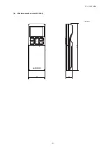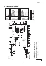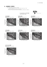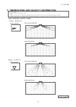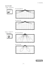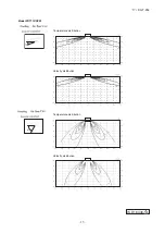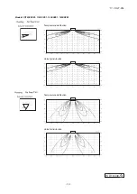
–
4
–
'17 • KX-T-254
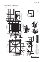
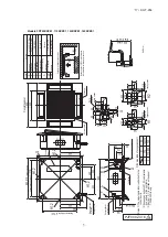
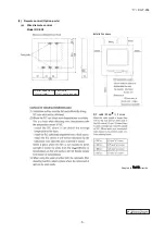
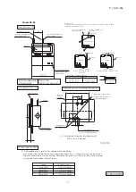
2. EXTERIOR DIMENSIONS
(1) Indoor unit
Models FDT28KXZE1, 36KXZE1, 45KXZE1, 56KXZE1, 71KXZE1
Unit
:
mm
A
Gas piping
B
Liquid piping
φ
6.35
(
1
/
4"
)(
Flare
)
C
Drain piping
VP25
(
O.D.32
)
D
Hole for wiring
F
Suspension bolts
(
M10 or M8
)
G
Space for installation and service
Obstacle
H1,2
G
H1,2
H1,2
Drain hose piece
B
A
F
C
(
Max. Drain lift
)
H1
H2
φ
125
(
Knock out
)
φ
200
(
Knock out
)
H1,2
D
G
1
770
2
770
-
800
725
725
-
770
P1
P2
Pattern
Symbol
Pitch area table of suspension bolt
Symbol
Content
Outside air opening for ducting
Air outlet opening for ducting
(
Knock out
)
or more
or more
Make a space of 4000 or more between the units when installing more than one.
Holes for tapping screws
Holes for tapping screws
Decorative panel
Air supply
Air return grille
Suspension bolts pitch
:
P1
(
Ceiling hole size
)
box
Control
Suspension bolts pitch
:
P2
(
Accessory
)
(
Installed on site
)
suspension bolt
Hanger plate for
Control box
Hole
Hole
Holes for tapping screws
Hole
H1 H2
φ
9.52
(
3
/
8"
)(
Flare
)
φ
15.88
(
5
/
8"
)(
Flare
)
φ
12.7
(
1
/
2"
)(
Flare
)
φ
9.52
(
3
/
8"
)(
Flare
)
Model
28
36,45,56
71
Anti draft function
(※
1
)
Notes
(
1
)
The model name label is attached to the
control box lid.
(
2
)
Suspension bolt pitch P1,P2 is adjustable
by a pattern of the right table.
(
3
)
Section 1
(※
1
)
is provided on the panel
T-PSAE-5A
W
-E only
.
1000
1000
□
630
□
950
(
778
)
860
-
910
(
725
)
568
420
420
245 303
333
50 or more
140
188
□
840
131
173
236
35
215
-
245
850 or less
88
100
100
60
140
140
6-
φ
4
88
100
130
240
140
6-
φ
4
200
76
112
137
67
50
38
37
40
65
5-
φ
4
105
44
13
A
PJF000Z417

