background image

-

 78 

-

Error code

Remote control:

LED

Green

Red

Indoor

Content

'19 • PAC-SM-302

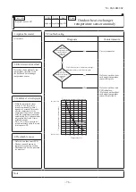
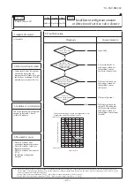
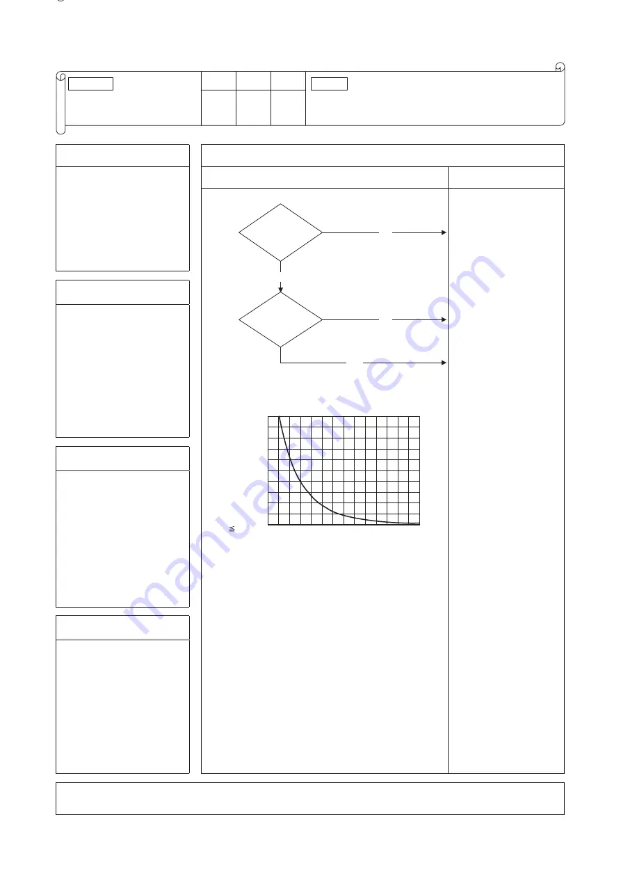
E39

Discharge pipe

temperature sensor anomaly

Keeps flashing Stays OFF

1. Applicable model

5. Troubleshooting

All models

Diagnosis

Countermeasure

Is the 

discharge pipe 

temperature sensor  

connector connected 

properly?

YES

Are the 

characteristics 

of discharge pipe 

temperature 

sensor OK?

NO

For the characteristics of discharge pipe 

temperature sensor, see the following graph.  

YES

140

120

100

80

60

40

20

0

0

100

50

[T    90

°C

]

NO

Temperature-resistance characteristics

Temperature sensor resistance (kΩ

)

Temperature (°C)

(Broken wire)

(Short-circuit)

Correct connector.

Defective discharge 

pipe temperature 

sensor

Replace.

Defective outdoor unit 

PCB

Replace.

(Defective temperature 

sensor input circuit)

2. Error detection method

Detection of anomalously low 

temperature (resistance) on 

the discharge pipe temperature 

sensor

3. Condition of error displayed

When the temperature sensor 

detects -25°C or lower for 5 

seconds continuously within 

10 minutes to 10 minutes 20 

seconds after the compressor 

ON, the compressor stops. After 

3-minute delay, the compressor 

starts again automatically, but 

if this anomalous temperature 

is detected 3 times within 40 

minutes.

4. Presumable cause

• Defective outdoor unit PCB

• Broken sensor harness or  

temperature sensing section 

(Check molding.)

• Disconnected wire connection 

(connector)

Note: 

Error code

Remote control:

LED

Green

Red

Outdoor unit control PCB

Outdoor unit

inverter PCB

Keeps flashing

Indoor unit control PCB

Stays OFF

Keeps flashing

Content

Keeps flashing

Yellow

8-time flash

Summary of Contents for FDT40ZSXW1VH

Page 1: ...Manual No 19 PAC SM 302 SERVICE MANUAL HYPER INVERTER PACKAGED AIR CONDITIONERS Split system air to air heat pump type CEILING CASSETTE 4 WAY TYPE FDT40ZSXW1VH 50ZSXW1VH 60ZSXW1VH ...

Page 2: ...Plural unit control Control of 16 units group by one remote control 20 External input output control CnT or CnTA 19 Abnormal temperature sensor return air indoor heat exchanger broken wire short circuit detection 21 Operation permission prohibition 23 Selection of cooling heating external input function 22 Temporary stop input 28 Energy saving operation RC EX3A only 29 Warm up control RC EX3A only...

Page 3: ...for diagnosis of inverter output 7 Outdoor unit control failure diagnosis circuit diagram 1 Selfdiagnosis function 2 Troubleshooting procedure 2 1 Diagnosing of microcomputer circuit 2 MAINTENANCE DATA 3 Troubleshooting at the indoor unit 4 Troubleshooting at the outdoor unit 5 Check of anomalous operation data with the remote control 15 Outdoor fan control at low outdoor temperature 16 Refrigerat...

Page 4: ...ht lighting can be changed If the backlight is ON setting when the screen is tapped while the backlight is turned off the backlight only is turned on Operations with switches and are excluded USB port USB connector mini B allows connecting to a personal computer For operating methods refer to the instruction manual attached to the software for personal computer remote control utility software Note...

Page 5: ...ent mode Cover AIR CON No button Display the indoor unit number connected to this remote control CHECK button This button is used at servicing TEST button This button is used during test operation Weekly timer display Displays the settings of the weekly timer Operation setting display area Displays setting temperature air flow volume operation mode and oparation message Operation check indicator l...

Page 6: ...d once again it stops operating MODE button Every time this button is pressed displays switch as below AUTO COOL HEAT FAN DRY TEMP button Change the set temperature by pressing or button FAN SPEED button The fan speed is switched in the following order 1 speed 2 speed 3 speed 4 speed AUTO 1 speed U D button Used to determine the up down louver position L R button Used to determine the left right l...

Page 7: ...r temperatures 2 CPU reset Reset CPU from the remote control as follows TOP screen Menu Service setting Service Maintenance Service password The selected screen is displayed The selected screen is displayed Service Maintenance 2 Special settings CPU reset Microcomputers of indoor unit and outdoor unit connected are reset State of restoration after power failure 3 Power failure compensation functio...

Page 8: ...function items are saved in the memory of indoor unit g Weekly timer peak cut timer or silent mode timer settings h Remote control function setting Please check the I U Set clock first on the initializing screen set the timer Other thanA C is connected 4 Alert displays If the following a to c appear check and repair as follows Communication check screen This appears if communications cannot be est...

Page 9: ...tate of stop is memorized Although the timer mode is cancelled at the recovery from power failure the setting of weekly timer is changed to the holiday setting for all weekdays b Operation mode c Air flow volume mode d Room temperature setting e Louver auto swing stop However the stop position 4 position is cancelled so that it returns to Position 1 f Remote control function items which have been ...

Page 10: ... of the temperature shown at right 3 3 Cooling operation Heating operation Room temperature detected with Thi A deg 59 56 Heating operation stopped cooling Heating OK Indoor heat exchanger temperature C b The following automatic controls are performed other than a above i Cooling or heating operation mode is judged according to the conditions of the Judgment based on Setting temperature Cooling se...

Page 11: ...mpressor 4 way valve Outdoor unit fan Indoor unit fan Drain pump 3 2 2 Thermostat ON Thermostat OFF 2 2 Notes 1 Operation Stop Turned ON OFF by the control other than the room temperature control 2 ON during the drain motor delay control 3 Drain pump ON setting may be selected with the indoor unit function setting of the wired remote control 3 Dehumidifying DRY operation Indoor ambient temperature...

Page 12: ...eekly timer Set the ON or OFF timer for a week Up to 8 patterns can be set for a day The day off setting is provided for holidays and non business days Note 1 It is necessary to set the clock to use the weekly timer vii Combination of patterns which can be set for the timer operations Note 1 Allowed Not Sleep time Sleep time Set OFF timer by hour Weekly timer Set ON timer by hour Set OFF timer by ...

Page 13: ...her detects 35 C or higher the fan operates with the set air flow volume c If the fan control at heating thermostat OFF is set at the Set air flow volume from the remote control the fan operates with the set air flow volume regardless of the thermostat ON OFF 2 Once the fan motor is changed from OFF to ON during the thermostat ON the indoor fan motor is not turned OFF even if the heat exchanger th...

Page 14: ...VER button to operate the swing louver when the air conditioner is operating SWING is displayed for 3 seconds and then the swing louver moves up and down continuously 2 To fix the swing louver at a position press one time the LOUVER button while the swing louver is moving so that four stop positions are displayed one after another per second When a desired stop position is displayed press the LOUV...

Page 15: ...n if the heat exchanger thermistors both Thi R1 and R2 detect 25 C or lower 2 Indoor fan OFF is fixed for 5 minutes After the 5 minutes the indoor fan is operated at ULo for 2 minutes In the meantime the louver is controlled at level 3 After operating at ULo for 2 minutes the indoor fan moves to the state of 1 above 4 If the thermostat is turned ON it moves to the hot start control 5 When the heat...

Page 16: ...the fan on the indoor unit of which the thermostat has been turned OFF is turned OFF The same occurs also when the remote control sensor is effective 9 Filter sign As the operation time Total ON time of ON OFF switch accumulates to 180 hours 1 FILTER CLEANING is displayed on the remote control This is displayed when the unit is in trouble and under the centralized control regardless of ON OFF Note...

Page 17: ...ng the drain detection switch OFF releases the forced drain pump ON condition Normal state 1 2 Normal state Drain detection switch ON Stop 1 Indoor unit operation mode Control A Control B Compressor ON Compressor OFF Cooling Dry Heating Fan 2 Notes 1 Including the stop from the cooling dehumidifying fan and heating and the anomalous stop 2 Including the Fan operation according to the mismatch of o...

Page 18: ... anomalous stop E20 b Selection of indoor fan speed If it enters the frost prevention control during cooling operation excluding dehumidifying the indoor fan speed is switched i When the indoor return air detection temperature detected with Thi A is 18 C or higher and the indoor heat exchanger temperature detected with Thi R detects the compressor frequency drop start temperature A C 1 C of indoor...

Page 19: ...s pressed at the next it is displayed orderly starting from the unit of smallest No d In case of anomaly If any anomaly occurs on a unit in a group a protective function operates that unit stops with the anomalous stop but any other normal units continue to run as they are e Signal wiring procedure Signal wiring between indoor and outdoor units should be made on each unit same as the normal wiring...

Page 20: ...nTA CnT CnT CnTA CnT CnTA Operation stop pulse CnT CnT CnT CnTA CnT CnT CnTA CnT CnTA Operationpermission prohibitionlevel CnT CnTA CnT CnTA CnT CnTA CnT CnT CnTA CnT CnTA Operation permission prohibition pulse CnT CnT CnT CnTA CnT CnT CnTA CnT CnTA Cooling heating selection level CnT CnTA CnT CnTA CnT CnTA CnT CnTA CnT CnT Cooling heating selection pulse CnT CnTA CnT CnTA CnT CnTA CnT CnTA CnT Cn...

Page 21: ...ooling heating 6 Forced thermo OFF Unit goes thermo off 7 Temporary stop Refer to 22 Temporary stop input 8 Silent mode Outdoor unit silent mode is activated ii In case of Pulse input setting Local setting It is effective only when the input signal to CnT 6 or CnTA is changed OFF ON and at that time unit operation ON OFF is inverted ON ON OFF OFF OFF ON ON ON ON Remote control OFF Remote control O...

Page 22: ... OFF Operation Stop Operation permission 1 Operation prohibition Unit stops 1 Only the LEVEL INPUT is acceptable for external input however when the indoor function setting of Level input Factory default or Pulse input is selected by the function for External input of the wired remote control operation status will be changed as follows In case of Level input setting In case of Pulse input setting ...

Page 23: ...ne Actual operation Remote control CnT Operation stop pulse CnTA Operation permission prohibition level Operation permission prohibition zone Actual operation Remote control Remote control ON Remote control OFF Remote control ON Remote control ON Remote control OFF Remote control ON ON ON ON ON ON ON ON OFF OFF OFF OFF OFF OFF OFF ON ON OFF ON ON ON ON ON OFF OFF OFF OFF OFF OFF Operation Operatio...

Page 24: ...es are inverted Cooling Heating or Heating Cooling d If the cooling heating selection signal is given by the external input the operation mode is transmitted to the remote control Selection of cooling heating external input function External input selection External input selection Cooling heating selection External input method Level External terminal input CnT or CnTA Cooling heating Cooling hea...

Page 25: ...on temperature by the return air temperature sensor and the measured temperature after installing the unit a It is adjustable in the unit of 0 5 C with the wired remote control indoor unit function RETURN AIR TEMP 1 0 C 1 5 C 2 0 C 1 0 C 1 5 C 2 0 C b Compensated temperature is transmitted to the remote control and the compressor to control them Note 1 The detection temperature compensation is eff...

Page 26: ...the return air temperature According to temperature difference between set temperature and return air temperature indoor fan tap are controlled automalically Auto 1 Changes the indoor fan tap within the range of Hi Me Lo Auto 2 Changes the indoor fan tap within the range of P Hi Hi Me Lo 35 Indoor unit overload alarm RC EX3A only If the following condition is satisfied at 30 minutes after starting...

Page 27: ... is high None When there is no one in the room When the None continues for 1 hour the FAN SPEED is set Lo MODE AUTO COOL HEAT mode operation COOL HEAT Set temperature 3ºC 33ºC 15ºC 3ºC Heat Source Activity Low Normal High None 37 Motion sensor control RC EX3A only The sensor determines the presence of people and the amount of activity and the following controls are done by the motion sensor Follow...

Page 28: ...2 66rps 12 78rps 12 90rps In case satisfied all of following conditions Connect compressor speed 0 rps 10 times or more Satisfy 1 2 and 3 conditions above Outdoor air temperature is 3 C or less 20 20 15 10 5 0 5 10 15 10 5 0 Outdoor air temperature Outdoor heat exchanger temperature 20 20 15 10 5 0 5 10 15 10 5 0 Outdoor air temperature Outdoor heat exchanger temperature Defrost operation start De...

Page 29: ...eed according to the following table 2 It checks the outdoor temperature TH2 once every hour to judge the operation range b Detail of operation Outdoor air temperature Lower limit speed 1 2 1 2 c Reset conditions The lower limit of compressor speed is set to 30 or 40 rps However when the thermo OFF the speed is reduced to 0 rps The outdoor fan is stepped up by 3 speed step Upper limit 8 th speed W...

Page 30: ...6 52 5 52 5 50 8 50 8 42 42 55 58 58 58 56 2 56 2 47 3 47 3 58 61 61 61 61 61 10 10 THi R 5 Heating high pressure control a Starting condition When the indoor heart exchanger temperature Thi R has risen to a specified temperature while the compressor is turned on b Compressor speed is controlled according to the zones of indoor heat exchanger temperature as shown by the following table 6 Heating o...

Page 31: ...ssor speed is 0 rps 4 6 8 10 12 2 4 Lower limit 35 rps Lower limit 45 rps Lower limit 45 rps Lower limit 35 rps Normal operation Outdoor air temperature C 6 8 Compressor overheat protection a Purpose b Detail of operation 1 Discharge pipe temperature C 180 180 180 Example Fuzzy 95 105 115 180 105 180 105 the com 2 j Current safe i Purpose ii Detail of operation k Current cut i Purpose ii Detail of...

Page 32: ...il of operation 3 Reset conditions Outdoor air temperature 10 C Outdoor air temperature 10 C Outdoor fan a b c min 1 21 C 38 C 09 SRK DB 087D 12 Serial signal transmission error protection a a Purpose b Detail of operation 13 Rotor lock 14 Outdoor fan motor protection 15 Outdoor fan control at low outdoor temperature Cooling 1 Operating conditions 2 Detail of operation 3 Reset conditions Outdoor a...

Page 33: ... operation 3 Reset conditions b a b a b 1 2 c When A minutes have elapsed after the compressor ON or the completion of the defrost operation Other than the defrost operation 3 When after satisfying the conditions of 1 and 2 above the compressor speed indoor air temperature Thi A and indoor heat exchanger temperature Thi R have satisfied the conditions in the following table for 5 minutes 3 2 at ea...

Page 34: ...erature sensor 63 Indoor control PCB Defective indoor control PCB Defective temperature sensor input circuit Replacement of PCB 1 time flash Keeps flashing Indoor return air temperature sensor Defective indoor return air temperature sensor defective element broken wire short circuit Poor contact of temperature sensor connector Replacement repair of temperature sensor 64 Indoor control PCB Defectiv...

Page 35: ...sor 78 Outdoor control PCB Defective outdoor control PCB Defective temperature sensor input circuit Replacement of PCB Stays OFF Keeps flashing Installation operation status Service valve gas side closing operation Replacement 79 Stays OFF Keeps flashing Outdoor control PCB compressor Current cut Anomalous compressor over current Replacement of PCB 80 81 Installation operation status Service valve...

Page 36: ...after initial communication was established Excessive number of connected indoor units by controlling with one remote control Whenever excessively connected indoor units is detected after power ON Return air temperature sensor anomaly 50 C or lower is detected for 5 seconds continuously within 60 minutes after initial detection of this anomalous temperature Indoor heat exchanger temperature sensor...

Page 37: ... fuse Note 1 With regard to parts of high voltage circuits and refrigeration cycle judge it according to ordinary inspection methods ii Instruction of how to replace indoor control PCB Read the SAFETY PRECAUTIONS carefully first of all and then strictly follow it during the replacement in order to protect yourself The precautionary items mentioned below are distinguished into two levels WARNING an...

Page 38: ...ed in i vii When there is no wire to connect to CNWR connect the supplied jumper connector Refer to Fig 2 If nothing is connected to CNWR it doesn t work even when power is turned on b Control PCB Parts mounting are different by the kind of PCB Equipped with reactor Fig 2 Equipped without reactor CNW3 White CNQ Red CNR White CNV2 Black CNV White CNH Black CNTA Blue CNL Black CNC White CNF Yellow C...

Page 39: ...erved Reserved Reserved Keep OFF Test run drain motor Normal Test run Normal Model selection As per model See table 1 Remark Address No setting at plural indoor units control by 1 R C 0 F Switch Description Default setting Table 1 Indoor unit model selection with SW6 1 SW6 4 40VH 50VH 60VH SW6 4 SW6 1 SW6 2 SW6 3 Default setting OFF OFF OFF OFF OFF ON ON ON ON ON ON ON Switch Keep OFF ...

Page 40: ...another error mode which has a higher priority than the previous error saved in memory occurs it is overwritten in memory and is displayed Reset of power source Be sure to avoid electrical shock when replacing or checking the outdoor unit control PCB because some voltage is still retained in the electrolytic capacitor on the PCB even after shutting down the power source to the outdoor unit Be sure...

Page 41: ... Temperature Current Target Super Heat Super Heat Discharge Pipe Super Heat Protection State No of The Compressor Outdoor Unit Fan Speed 63H1 On Off Defrost Control On Off Total Running Hours of The Compressor Pulse of The Outdoor Unit Expansion Valve EEVC Pulse of The Outdoor Unit Expansion Valve EEVH 13 Supply Air Temperature ە Details of compressor protection status No 33 No Contents of display...

Page 42: ...e pipe temperature anomaly 3 Current safe control of inverter primary current 4 High pressure protection control 5 High pressure anomaly 6 Low pressure protection control 7 Low pressure anomaly 8 Anti frost prevention control 9 Current cut 10 Power transistor protection control 11 Power transistor anomaly Overheat 12 Compression ratio control 13 Spare 14 Dewing prevention control 15 Current safe c...

Page 43: ...starting check operation 6 Inverter checker for diagnosis of inverter output Checking method LED U V W LED1 LED3 LED5 LED2 LED4 LED6 LED1 LED3 LED5 LED2 LED4 LED6 LED1 LED3 LED5 LED2 LED4 LED6 LED1 LED3 LED5 LED2 LED4 LED6 LED1 LED3 LED5 LED2 LED4 LED6 LED1 LED3 LED5 LED2 LED4 LED6 ON OFF status of LED If all of LED are ON OFF according to following pattern If all of LED stay OFF or some of LED ar...

Page 44: ...if the voltage oscillates between DC0 and approx 20V Inspection power transistor Remove the faston terminal and test output voltage Inspection of outdoor fan motor See page 44 Check point of outdoor unit Color Color symbol RD Mark Yellow Green Y G Black BK Blue BL Yellow YE White WH Red Display Voltage range Voltage check in PCB The normal range is as follows DC280V DC230V DC310V DC 20V DC 18V DC ...

Page 45: ... 44 19 PAC SM 302 ...

Page 46: ...nomaly 63 E7 Return air temperature sensor anomaly 64 E8 Heating overload operation 65 E9 Drain trouble 66 E10 Excessive number of connected indoor units more than 17 units by controlling with one remote control 67 E11 Address setting error of indoor units 68 E16 Indoor fan motor anomaly 69 E19 Indoor unit operation check drain pump motor check setting error 70 E20 Indoor fan motor rotation speed ...

Page 47: ...sor operating NO YES NO Note 1 Outdoor 35 C Indoor 27 C 1 WAIT It is normal This unit is designed to start in the soft start mode by detecting the under dome temperature of compressor when it restart after power reset It is necessary to replace to higher capacity one or to install additional unit Compressor refrigerant oil protection control at starting is activated For the contents of control ref...

Page 48: ... Note 1 Outdoor 7 C Indoor 20 C 1 WAIT It is normal This unit is designed to start in the soft start mode by detecting the under dome temperature of compressor when it restart after power reset It is necessary to replace to higher capacity one or to install additional unit Compressor refrigerant oil protection control at starting is activated For the contents of control refer to the compressor sta...

Page 49: ...n left for long time without power source the insulation resistance may drop to a few MΩ because of refrigerant migrated in the compressor When the earth breaker is activated at lower insulation resistance check the following points When power ON crankcase heater heat up compressor and evaporate the refrigerant migrated in the compressor Check if the earth leakage breaker is conformed to higher ha...

Page 50: ...to the gap if necessary Prevent the vibration from transmitting to wall and etc by fixing pipes on the wall or wrapping rubber cushion around the pipe which goes through the hole in the wall or applying other appropriate means Strength of ceiling wall floor etc may be insufficient Review the installing position or reinforce it Check for leaning of installed unit or anomalous mounting of fan louver...

Page 51: ... piping of air conditioner It is likely to occur particularly during cooling or defrost operation in the heating mode It is normal The noise vibration occurs when the refrigerant starts or stops flowing It is normal When the defrost operation starts or stops during heating the refrigerant flow is reversed due to switching 4 way valve This causes a large change in pressure which produces a blowing ...

Page 52: ...usion of air nitrogen etc In such occasion it is necessary to recover refrigerant vacuum dry and recharge refrigerant Since there could be many causes of noise vibration the above do not cover all In such case check the conditions when where how the noise vibration occurs according to following check point Indoor outdoor unit Cooling heating fan mode Startup stop during operation Operating conditi...

Page 53: ...at the indoor unit side LM louver motor Is the louver operable with the remote control YES NO Does the louver operate at the power on YES NO YES NO Operate after waiting for more than 1 minute Repair wiring Defective indoor unit control PCB Replace Replace LM Normal Adjust LM lever and then check again 2 Error detection method 3 Condition of error displayed 4 Presumable cause Defective LM LM wire ...

Page 54: ...or unit NO YES NO Is AC380 415V for 3 phase unit detected between ձ ղ and ճ on the teminal block of outdoor unit or isAC220 240V for 1 phase unit detected between ձ and ղ on the terminal block of outdoor unit YES Defective outdoor unit control PCB Noise filter Misconnection or breakage of connecting wires Defective indoor unit control PCB Replace Replace FM LM etc Replace fuse Defective indoor uni...

Page 55: ...Y in the indoor terminal block exceed 15 VDC YES NO YES NO NO YES Does the voltage between X and Y in the indoor terminal block exceed 15 VDC Remove wire for the remote control Power source reset YES Correct Remote control wire breakage Replace remote control Malfunction by temporary noise Defective indoor unit control PCB Replace Remote control wire breakage Replace remote control 2 Error detecti...

Page 56: ...wire between the indoor and outdoor unit Power source reset NO YES YES NO NO NO NO NO YES YES YES Set one remote control for Master and the other for Slave Set SW1 on remote control PCB at Master Set address again SW2 on indoor unit control PCB Separate remote control wires from high voltage wires Defective indoor unit control PCB Replace Defective remote control Change 2 Error detection method Co...

Page 57: ...on with remote control 3 Condition of error displayed Same as above 4 Presumable cause Improper setting Surrounding environment Defective remote control communication circuit Faulty indoor unit control PCB Faulty outdoor unit control PCB Note If any error is detected 30 minutes after displaying WAIT on the remote control the display changes to INSPECT I U NO NO NO NO NO Are more than 3 units of re...

Page 58: ... NO Is approx DC20V detected between on the indoor unit terminal block NO YES WAIT See next page Defective outdoor unit PCB Replace Connect properly Replace fuse Defective indoor unit control PCB Replace Replace indoor unit control PCB Defective remote control Replace Broken remote control wire Y Replace Correct connection wires between indoor and outdoor units Defective outdoor unit PCB Replace D...

Page 59: ...acing the power source fuse Diagnosis Countermeasure Replace the outdoor unit PCB YES YES NO YES Replace the outdoor unit PCB NO Replace the reactor NO Isn t there a short circuit between phases of outdoor unit PCB Aren t there cracks or burning on the power transistor module or diode stack Isn t reactor the anomalous Replace fuse 2 Error detection method 3 Condition of error displayed 4 Presumabl...

Page 60: ... flashing twice Are wires connected properly between the indoor and the outdoor units Is approx DC20V detected between on the outdoor unit terminal block NO Is approx DC20V detected between on the indoor unit terminal block NO 2 N YES YES YES YES YES Replace fuse Short circuit on remote control wire Defective remote control Defective indoor unit control PCB Replace Defective remote control Broken ...

Page 61: ...nection terminals Is DC10V or higher detected on remote control wires if the remote control is removed Are wires connected properly between the indoor outdoor units NO Defective remote control Defective remote control Defective connecting wire Defective remote control wire Short circuit etc Defective indoor unit control PCB Replace 2 Error detection method 3 Condition of error displayed 4 Presumab...

Page 62: ...r source reset NO Malfunction by noise Check peripheral environment Defective indoor unit control PCB Replace Move to E5 Communication error during operation check 2 Error detection method When normal communication between the remote control and the indoor unit is interrupted for more than 2 minutes Detectable only with the remote control 3 Condition of error displayed Same as above 4 Presumable c...

Page 63: ...ge of signal wires between indoor outdoor units YES NO YES NO YES NO In case that the outdoor unit red LED flashes 2 time Repair signal wires Repair signal wires To the diagnosis of WAIT Unit is normal Malfunction by temporary noise etc Defective outdoor unit PCB Defective network communication circuit Replace Unit is normal Malfunction by temporary noise etc 2 Error detection method When normal c...

Page 64: ...nger temperature sensor Replace Defective indoor unit control PCB Replace Defective indoor heat exchanger temperature sensor input circuit 2 Error detection method Anomalously low temperature or high temperature resistance is detected on the indoor heat exchanger temperature sensor Thi R1 R2 or R3 3 Condition of error displayed When the temperature sensor detects 50 C or lower for 5 seconds contin...

Page 65: ...nect connector Defective return air temperature sensor Replace Defective indoor unit control PCB Replace Defective return air temperature sensor input circuit 2 Error detection method Anomalously low temperature or high temperature resistance is detected by indoor return air temperature sensor Thi A 3 Condition of error displayed When the temperature sensor detects 50 C or lower for 5 seconds cont...

Page 66: ...e 2 For characteristics of indoor heat exchanger temperature sensor see the error display E6 YES NO YES NO Error stop Reset Indoor heat exchanger temperature C 56 63 Wash Defective indoor heat exchanger temperature sensor connector Correct Defective indoor heat exchanger temperature sensor Check refrigerant system Adjust 2 Error detection method Indoor heat exchanger temperature sensor Thi R1 R2 R...

Page 67: ... NO YES NO Check float switch Defective indoor unit control PCB Replace Defective indoor unit control PCB Replace Check option equipment Correct setting to Humidifier drain pump motor interlock Defective indoor unit control PCB Replace Check wiring of drain motor Correct Check drain pump motor 2 Error detection method Float switch is activated 3 Condition of error displayed If the float switch OPE...

Page 68: ... Troubleshooting All models Diagnosis Countermeasure Aren t more than 17 indoor units connected to one remote control NO YES Defective remote control Replace Reduce to 16 or less units 2 Error detection method When it detects more than 17 of indoor units connected to one remote contorl 3 Condition of error displayed Same as above 4 Presumable cause Excessive number of indoor units connected Defect...

Page 69: ...vice setting IU settings Select IU In cases of RC E5 Return address No to IU using or button 2 Error detection method IU address has been set using the Master IU address set function of remote control 3 Condition of error displayed Same as above 4 Presumable cause Same as above Note Is Master IU address set function of remote control used E11 occurs YES IU IU IU R C In case the wiring is below and...

Page 70: ...eplace faulty fan motor and indoor unit control PCB Replace fan motor If the error persists after replacing the fan motor replace the indoor unit control PCB Malfunction by temporary noise 2 Error detection method Detected by rotation speed of indoor fan motor 3 Condition of error displayed When actual rotation speed of indoor fan motor drops to lower than 200min 1 for 30 seconds continuously the ...

Page 71: ...ol PCB ON E19 occurs when the power ON NO YES Defective indoor unit control PCB Defective SW7 Replace Turn SW7 1 on the indoor unit control PCB OFF and reset the power 2 Error detection method After indoor operation check when the communication between indoor and outdoor unit is established and SW7 1 is still kept ON 3 Condition of error displayed Same as above 4 Presumable cause Mistake in SW7 1 ...

Page 72: ...n motor Check power voltage Replace faulty fan motor and indoor unit control PCB Replace fan motor If the error persists after replacing the fan motor replace the indoor unit control PCB Malfunction by temporary noise 2 Error detection method Detected by rotation speed of indoor fan motor 3 Condition of error displayed When the actual fan rotation speed does not reach to the speed of required spee...

Page 73: ...ndoor unit control PCB 2 Error detection method Panel switch PS has detected Open for more than 1 second 3 Condition of Error displayed Same as above 4 Presumable cause Defective panel switch Disconnection of wiring Defective indoor unit control PCB Note Does matter improve if panel switch is turned ON forcibly after resetting error Is grill opened NO YES NO YES YES Are connectors at right inserte...

Page 74: ...delay the compressor starts again automatically but if this error occurs again within 60 minutes after the initial detection 4 Presumable cause Faulty connection of remote control temperature sensor Defective remote control temperature sensor Defective remote control PCB Note After 10 seconds has passed since remote control temperature sensor was switched from valid to invalid E28 will not be disp...

Page 75: ...mperature sensor Check unit side Isn t the air circulation of outdoor unit short circuited Are installation spaces adequate Isn t there any fouling or clogging on heat exchanger Control operation check Defective outdoor unit PCB Replace Excessive refrigerant amount Recharge refrigerant by weighing proper amount on a scale 2 Error detection method Anomalous stop Reset 53 51 63 56 Outdoor heat excha...

Page 76: ...e sensor Insufficient refrigerant amount Recharge refrigerant by weighing proper amount on a scale Control operation check Defective outdoor unit PCB Replace Check unit side Isn t filter clogged Are adequate indoor outdoor unit installation spaces Isn t there any short circuit of air Isn t there any fouling clogging on indoor heat exchanger 2 Error detection method For the error detection method r...

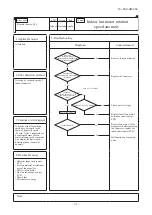
Page 77: ...ective outdoor heat exchanger temperature sensor Replace Defective outdoor unit PCB Replace Defective outdoor heat exchanger temperature sensor input circuit 2 Error detection method Detection of anomalously low temperature resistance on the outdoor heat exchanger temperature sensor 3 Condition of error displayed When the temperature sensor detects 55 C or lower for 20 seconds continuously within ...

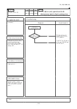
Page 78: ...tdoor air temperature sensor Replace Defective outdoor unit PCB Replace Defective outdoor air temperature sensor input circuit 2 Error detection method Detection of anomalously low temperature resistance on outdoor air temperature sensor 3 Condition of error displayed When the temperature sensor detects 55 C or lower for 5 seconds continuously within 2 minutes to 2 minutes 20 seconds after the com...

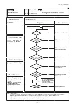
Page 79: ...Broken wire Short circuit Correct connector Defective discharge pipe temperature sensor Replace Defective outdoor unit PCB Replace Defective temperature sensor input circuit 2 Error detection method Detection of anomalously low temperature resistance on the discharge pipe temperature sensor 3 Condition of error displayed When the temperature sensor detects 25 C or lower for 5 seconds continuously ...

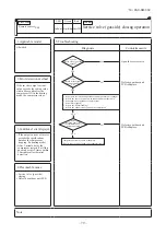
Page 80: ...e any anoumalous sound on the compressor YES YES YES Are the service valve gas side opened Open the service valve Defective outdoor unit PCB Replace Defective outdoor unit PCB Replace 2 Error detection method If the inverter output current value exceeds the setting value within 80 seconds after the compressor ON in the heating mode the compressor stops 3 Condition of error displayed If the output ...

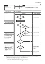
Page 81: ...the valves Check refrigerant amount and refregerant circuit In case of transitional increase of high pressure and or test run several times restarting may recover it because liquid refrigerant migrated in the compresser is discharged from the compressor Replace compressor 2 Error detection method In order to prevent from overcurrent of inverter if the current exceeds the specifications it makes th...

Page 82: ... At heating does the indoor fan motor run Are the service valves fully opened Is the filter clogged Is there any liquid flooding Is the superheat within normal range Is the low pressure sensor and suction pipe temperature sensor normal Is there any anoumalous sound on the compressor YES YES From previous page Defective outdoor unit PCB Replace Defective outdoor unit PCB Replace 2 Error detection m...

Page 83: ...ive outdoor unit PCB Replace 2 Error detection method Error is displayed if the converter voltage exceeds target voltage 3 times within 20 minutes Remote control may be set after 3 minute delay Error is displayed if the converter voltage is lower than DC210V 1 time within 5 seconds after power ON 3 Condition of error displayed Same as above 4 Presumable cause Defective outdoor unit PCB Dust on out...

Page 84: ...rary noise 2 Error detection method Detected by rotation speed of outdoor fan motor 3 Condition of error displayed When actual rotation speed of outdoor fan motor drops to 75min 1 or lower for 30 minutes continuously the compressor and the outdoor fan motor stop After 3 minute delay it starts again automatically but if this anomaly occurs 3 times within 60 minutes after the initial detection 4 Pre...

Page 85: ... method 3 Condition of error displayed 4 Presumable cause Note If the power transistor primary current exceeds the setting value for 3 seconds the compressor stops Power transistor primary current Outdoor unit PCB anomaly Dust on outdoor unit PCB Blown F2 fuse Check soldered surfaces on the outdoor unit PCB for foreign matter like dust fouling etc Isn t F2 fuse 250V 20A blown Remove foreign matter...

Page 86: ...ctive indoor unit control PCB Replace Defective indoor heat exchanger return air temperature sensor input circuits 2 Error detection method Judge insufficient refrigerant amount by detecting the temperature differnce between indoor heat exchanger Thi R and indoor return air Thi A 3 Condition of error displayed When the insufficient refrigerant amount is detected 3 times within 60 minutes 4 Presuma...

Page 87: ...cessive refrigerant amount Indoor outdoor unit installation spaces Faulty compressor Defective outdoor air temperature sensor Defective outdoor unit PCB Diagnosis Countermeasure 2 Error detection method 3 Condition of error displayed 4 Presumable cause Note Is outdoor ventilation condition good Inspect outdoor air temperature sensor Is the refrigerant amount nomal Adjust the refrigerant amount pro...

Page 88: ...place Defective outdoor unit PCB Replace Repalce compressor 2 Error detection method If it fails to change over to the rotor detection operation of compressor motor 3 Condition of error displayed If compressor fails to startup for 42 times 4 Presumable cause Outdoor fan motor anomaly Outdoor unit PCB anomaly Anomalous power source voltage Improper refrigerant amount and refrigerant circuit Faulty ...

Page 89: ...Condition of error displayed If it fails again to detect the rotor position after shifting to the compressor rotor position detection operation the compressor stops 4 Presumable cause Defective outdoor fan motor Defective outdoor unit PCB Anomalous power source voltage Improper refrigerant amount and refrigerant circuit Defective compressor motor bearing Note Insulation resistance The unit is left...

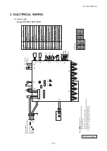
Page 90: ...2 3 4 5 6 7 8 9 10 11 12 13 14 15 16 17 18 19 20 BK BK BK BK BK BK BK BK BK BL RD BR OR WH YE GN RD 12 12 12 3 Power source line Signal line 1 2 3 CNW3 WH 1 3 WH BL 2 0A 3 15A WH YE GN PIS WHWHWHWHWHWHWHWHWHWHBL BL BL BL BL BL BL BL BL BL RD RD RD RD RD RD RD RD RD RD SW2 1 BK BK BK BK BK RD WH E1 Indoor unit PCB 1 2 Option Remote operation input volt free contact The line between indoor unit and ...

Page 91: ...ications are based on the assumption that a metal or plastic conduit is used with no more than three cables contained in a conduit and a voltage drop is 2 For an installation falling outside of these conditions please follow the national or regional electricity regulations The wire numbers include earth wire Yellow Green regulations 2 N M BK WH RD V W U PCB ASSY PCB1 M MS TRANSISTOR POWER POWER T ...

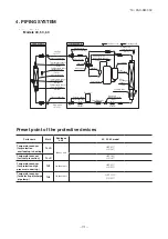
Page 92: ...4way valve Suction Muffler Discharge Compressor Check joint Check joint Check joint Accumulator Check valve Thermistor ThO R2 φ9 52 Gas line φ15 88 Liquid line Strainer Temperature sensor Return temp Thi A Temperature sensor Heat exchanger Thi R3 Temperature sensor Heat exchanger Thi R2 Heat exchanger Flare connecting Flare connecting Cooling cycle Heating cycle 1 Single type Accumulator Service v...

Page 93: ...C MITSUBISHI HEAVY INDUSTRIES THERMAL SYSTEMS LTD 16 5 Konan 2 chome Minato ku Tokyo 108 8215 Japan http www mhi mth co jp en HYPER INVERTER PACKAGED AIR CONDITIONERS Air Conditioning Refrigeration Systems 16 5 Konan 2 chome Minato ku Tokyo 108 8215 Japan http www mhi co jp Copyright MITSUBISHI HEAVY INDUSTRIES LTD Because of our policy of continuous improvement we reserve the right to make change...

Reviews: