background image

-

 68 

-

 '14 • KX-T-222

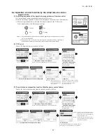
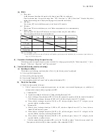
(a)  Output for external control (remote display)


Following output connectors (CnT) are provided on the indoor control PCB for monitoring operation status.

  Operation output:

 Outputs DC12V signal for driving relay during operation

  Heating output:

 Outputs DC12V signal for driving relay during heating operation

  Thermostat ON output:

 Outputs DC12V signal for driving relay when compressor is operating.

  Error output:

 Outputs DC12V signal for driving relay when anomalous condition occurs.

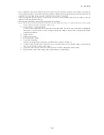
(b)  Remote operation input


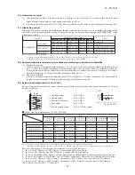
Remote operation input connector (CnT-6 or CnTA) is provided on the indoor control PCB.


However remote operation by CnT-6 or CnTA is not effective, when “Center mode” is selected by central control.


In case of plural unit (twin, triple, double twin), remote operation input to CnT-6 or CnTA on the slave indoor unit is 
invalid.


Only the “LEVEL INPUT” is acceptable for external input

, however when the indoor function setting of “Level 

input (Factory default)” or “Pulse input” is selected by the function for “External input” of the wired remote control, 
operation status will be changed as follows.

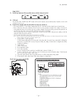
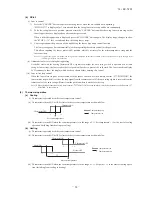
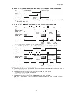
(i)  In case of “Level input” setting (Factory default)


Input signal to CnT-6 or CnTA is OFF→ON …… unit ON


Input signal to CnT-6 or CnTA is ON→OFF …… unit OFF


Operation is not inverted.

ON

ON

OFF

OFF

OFF

ON

ON

ON

ON

Remote
control OFF

Remote
control ON

Remote
control OFF

Remote
control ON

OFF

OFF

ON

ON

OFF

OFF

ON

OFF

OFF

OFF

OFF

ON

ON

OFF

OFF

CnT-6 or CnTA input

Unit A

Unit B

CnT-6 or CnTA input

Unit A

Unit B


Note: The latest operation has priority


It is available to operate/stop by remote control or central control

 (ii)  In case of “Pulse input” setting (Local setting)


It is effective only when the input signal to CnT-6 or CnTA is changed OFF→ON, and at that time unit operation [ON/

OFF] is inverted.

ON

ON

OFF

OFF

OFF

ON

ON

ON

ON

Remote
control OFF

Remote
control ON

Remote
control OFF

Remote
control ON

OFF

OFF

ON

ON

OFF

OFF

ON

OFF

OFF

OFF

OFF

ON

ON

OFF

OFF

CnT-6 or CnTA input

Unit A

Unit B

CnT-6 or CnTA input

Unit A

Unit B
Summary of Contents for FDU1100FKXZE1

Page 1: ...connected High static pressure type FDU224KXZE1 FDU650FKXZE1 KXZ series 1 Regarding the outdoor unit KXZ series refer to the No 14 KX DB 199 No 14 KX DB 201 Note Outdoor air processing unit No 14 KX DB 203 and No 14 KX DB 207 280KXZE1 1100FKXZE1 1800FKXZE1 2400FKXZE1 TECHNICAL MANUAL ...

Page 2: ... Outdoor air processing unit FDU F 7 2 Electric wiring work instruction 7 3 Installation manual for wired remote control option parts 8 OUTLINE OF OPERATION CONTROL BY MYCROCOMPUTER 8 1 Remote control option parts 8 2 Operation control function by the wired remote control 3 4 7 7 9 1 Models FDU224KXZE1 280KXZE1 Models FDU1800FKXZE1 2400FKXZE1 2 Models FDU650FKXZE1 1100FKXZE1 1 Model RC EX1A 2 Mode...

Page 3: ...ch Option Wired RC E5 RC EX1A RCH E3 Wireless RCN KIT3 E Remote control switch Option Wired RC E5 RC EX1A RCH E3 Wireless RCN KIT3 E Room temperature control Thermostat by electronics Thermostat by electronics Safety equipment Overload protection for fan motor Frost protection thermostat Overload protection for fan motor Frost protection thermostat Installation data Refrigerant piping size Liquid ...

Page 4: ...thane form Polyurethane form Operation control Operation switch Remote control switch Option Wired RC EX1A RC E5 RCH E3 Remote control switch Option Wired RC EX1A RC E5 RCH E3 Remote control switch Option Wired RC EX1A RC E5 RCH E3 Remote control switch Option Wired RC EX1A RC E5 RCH E3 Room temperature control Thermostat by electronics Thermostat by electronics Thermostat by electronics Thermosta...

Page 5: ...ore Case 2 From bottom of unit Inspection hole 880 Notes 1 The model name label is attached on the lid of the control box b Install refrigerant pipes not to cross marked area drain pipe and wiring so as Note a out 2 fan units For fan units maintenance Notes a There must not be obstacle to draw refer to the service manual Pipe c Fan unit c The case that pipes are installed to upper bottom of fan un...

Page 6: ...d services 600 1300 100 or more or more Inspection hole 620 Note 1 The model name label is attached on the lid of the control box Case 2 From bottom of unit Slab or more 20 20 or more 370 Ceiling Note b Note a 15 out fan unit For fan unit maintenance b Install refrigerant pipes Notes a There must not be obstacle to draw drain pipe and wiring so as refer to the service manual c The case that pipes ...

Page 7: ...0 113 φ170 φ124 φ170 69 295 325 E 43 170 Duct dimension Duct dimension tapping screws Holes for 4 φ4 1000 Space for installation and service 150 200 100 200 H 100 Slab or more 20 20 or more Note a or more or more 370 Ceiling Note b Case 1 From side of unit Select either of two cases to keep space for installation and services 600 1720 100 or more or more Case 2 From bottom of unit Inspection hole ...

Page 8: ...f unit Inspection hole 880 Notes 1 The model name label is attached on the lid of the control box b Install refrigerant pipes not to cross marked area drain pipe and wiring so as Note a out 2 fan units For fan units maintenance Notes a There must not be obstacle to draw refer to the service manual Pipe c Fan unit c The case that pipes are installed to upper bottom of fan unit keep space of 60mm or...

Page 9: ...d remote control option parts 1 Model RC EX1A Installation space R C cable 0 3mm2 2 core Adapted to RoHS directive Exterior appearance Munsell color Pearl White N8 5 near equivalent Dimensions Viewed from front A PJZ000Z297 ...

Page 10: ... cace Board Wiring Upper Lower X Y Sheath Upper cace Board Wiring Upper Lower Y X Tighten the screws after cutting off the thin part of screw mounting part Embedded mounting The peeling off length of sheath The peeling off length of sheath In case of pulling out from upper left In case of pulling out from upper left In case of pulling out from upper left X wiring 170mm Y wiring 190mm Pulling out f...

Page 11: ...D 2 Connector CNA Z Green Normaloperation Model capacity setting SW6 Operation check Drain motor test run SW7 1 SW5 1 Thermistor Remote control Thermistor Heat exchanger Thermistor Return air Thc Th R1 2 3 Th A TB2 Terminal block Signal line 口 mark TB1 Terminal block Power source mark I I SW2 Automatic adjustment Fixed previous L Reactor F1 3 Fuse FM1 2 Fan motor Powerful mode Valid Invalid SW7 3 ...

Page 12: ... SVG SVE XB1 XB2 XB3 XB4 1 2 3 4 5 CNT2 RD 12 Notes 1 indicates wiring on site 2 Use twin core shielded cord 0 75 1 25mm2 at signal line between indoor unit and outdoor unit and signal line between indoor units 3 Use twin core cord 0 3mm 2 at remote control line See spec sheet of remote control in case that the total length is more than 100m 4 Do not put signal line and remote control line alongsi...

Page 13: ...ource 220V 60Hz between indoor units Power source line Earth line RD RD 1 2 CNI BL FS CNZ CND For HA WH BK 1 2 CNTA BL RD t Control PCB RD YE t YE BK t BK 1 2 3 4 5 6 BK t BK 1 2 XR1 XR2 XR3 XR4 XR5 Remote operation 1 2 3 4 5 6 12 SW2 SW6 SW5 SW7 LED 2 LED 3 X Y 1 3 X Y t TB2 WH BK CNB WH CNN YE CNH BK CNT BL M 1 4 5 6 7 RD F4 2A CNM2 BK Operation Heating ThermoON Inspection ThC Th R1 Th R2 Th R3 ...

Page 14: ...tion check Drain motor test run SW7 1 SW5 1 Thermistor Remote control Thermistor Heat exchanger Thermistor Return air Thc Th R1 2 3 Th A TB2 Terminal block Signal line 口 mark TB1 Terminal block Power source mark I I SW2 Automatic adjustment Fixed previous L Reactor F1 3 Fuse FM1 2 Fan motor Powerful mode Valid Invalid SW7 3 JSL1 Live superlink terminal setting For spare SW5 2 Indoor unit address h...

Page 15: ...ssure loss of the duct connected 6HWWLQJ 3D 6HWWLQJ 3D 6HWWLQJ 3D 6HWWLQJ 3D KDUDFWHULVWLF 1 KDUDFWHULVWLF 1 LU IORZ P3 PLQ WHUQDO VWDWLF SUHVVXUH 3D LU IORZ P3 PLQ WHUQDO VWDWLF SUHVVXUH 3D 5DQJH RI DSSURYDEOH DLU IORZ Q FDVH DFWXDO 6 3 FRUUHFSRQG VHWWLQJ RI 6 3 76 84 88 LU IORZ P3 PLQ WHUQDO VWDWLF SUHVVXUH 3D ŠSW8 4 OFF Range of use limitation Setting 80Pa 150Pa KDUDFWHULVWLF 1 KDUDFWHULVWLF 1 ...

Page 16: ...re Pa 0 20 40 60 80 100 120 140 160 180 200 220 240 5 6 7 8 15 Air flow m3 min External static pressure Pa Range of approvable air flow In case actual E S P correcpond setting of E S P 0 20 40 60 80 100 120 140 160 180 200 220 240 7 9 11 13 15 Air flow m3 min External static pressure Pa SW8 4 OFF Range of use limitation Setting 10Pa 120Pa Characteristic FAN 1 Characteristic FAN 2 0 20 40 60 80 100...

Page 17: ...atic pressure Pa SW8 4 OFF Range of use limitation Setting 10Pa 120Pa Characteristic FAN 1 Characteristic FAN 2 0 20 40 60 80 100 120 140 160 180 200 220 240 Air flow m3 min External static pressure Pa Range of approvable air flow In case actual E S P correcpond setting of E S P SW8 4 ON Range of use limitation Setting 10Pa 200Pa 16 18 20 22 24 16 18 20 22 24 12 16 Setting 120Pa Setting 60Pa Setti...

Page 18: ...4 OFF Range of use limitation Setting 10Pa 120Pa Characteristic FAN 1 Characteristic FAN 2 0 20 40 60 80 100 120 140 160 180 200 220 240 Air flow m3 min External static pressure Pa Range of approvable air flow In case actual E S P correcpond setting of E S P SW8 4 ON Range of use limitation Setting 10Pa 200Pa 28 30 36 38 40 26 28 30 32 20 34 22 26 Setting 120Pa Setting 60Pa Setting 10Pa Hi Lo Hi L...

Page 19: ...4 OFF Range of use limitation Setting 10Pa 120Pa Characteristic FAN 1 Characteristic FAN 2 0 20 40 60 80 100 120 140 160 180 200 220 240 Air flow m3 min External static pressure Pa Range of approvable air flow In case actual E S P correcpond setting of E S P SW8 4 ON Range of use limitation Setting 10Pa 200Pa 36 38 44 46 48 34 36 38 40 30 44 32 36 Setting 120Pa Setting 60Pa Setting 10Pa Hi Lo Hi L...

Page 20: ... N60 Mid Octave Band Frequency Hz Souud Pressure Level dB standard 2 10 5 Pa Noise level 37dB A at High 63 125 250 500 1000 2000 4000 8000 20 10 30 40 50 60 20 10 30 40 50 60 N30 N40 N20 N50 N60 Mid Octave Band Frequency Hz Souud Pressure Level dB standard 2 10 5 Pa Models FDU1100FKXZE1 Models FDU1800FKXZE1 Noise level 42dB A at High 63 125 250 500 1000 2000 4000 8000 20 10 30 40 50 60 20 10 30 40...

Page 21: ...TC SHC TC SHC DB WB 16 DB 18 DB 20 DB 22 DB 24 DB 10 14 75 14 14 17 64 15 96 19 08 16 21 20 30 16 38 22 74 17 73 23 61 17 36 19 8 20 11 60 11 60 11 60 11 60 11 60 12 14 75 14 14 17 64 15 96 19 08 16 21 20 27 16 37 22 66 17 71 23 51 17 33 17 8 18 12 35 12 35 12 35 12 35 12 35 14 14 75 14 14 17 64 15 96 19 08 16 21 20 24 16 36 22 57 17 68 23 41 17 30 15 7 16 13 09 13 09 13 09 13 09 13 09 16 14 75 14...

Page 22: ... WB 22 WB 24 WB Air flow DB TC SHC TC SHC TC SHC TC SHC TC SHC TC SHC TC SHC DB WB 16 DB 18 DB 20 DB 22 DB 24 DB 10 18 36 15 65 21 95 17 67 23 74 18 01 25 26 18 26 28 30 19 77 29 38 19 26 19 8 20 14 62 14 62 14 62 14 62 14 62 12 18 36 15 65 21 95 17 67 23 74 18 01 25 23 18 25 28 19 19 73 29 25 19 22 17 8 18 15 56 15 56 15 56 15 56 15 56 14 18 36 15 65 21 95 17 67 23 74 18 01 25 19 18 24 28 09 19 7...

Page 23: ... Heating Mode kW Air flow m3 min Outdoor air temp 10 WB 5 WB 0 WB 4 WB 8 WB 12 WB 10 DB 8 10 0 00 0 00 0 00 0 00 0 00 5 DB 7 30 7 30 0 00 0 00 0 00 0 00 0 DB 6 49 6 50 6 50 0 00 0 00 0 00 4 DB 5 50 5 50 5 51 5 51 0 00 0 00 8 DB 4 53 4 53 4 53 4 54 4 54 0 00 12 DB 3 58 3 58 3 58 3 59 3 59 3 59 16 DB 2 50 2 50 2 50 2 50 2 50 2 50 20 DB 1 54 1 54 1 54 1 54 1 54 1 54 10 DB 8 62 0 00 0 00 0 00 0 00 0 0...

Page 24: ...p 10 WB 5 WB 0 WB 4 WB 8 WB 12 WB 10 DB 12 90 0 00 0 00 0 00 0 00 0 00 5 DB 11 70 11 70 0 00 0 00 0 00 0 00 0 DB 10 49 10 49 10 50 0 00 0 00 0 00 4 DB 8 88 8 89 8 89 8 90 0 00 0 00 8 DB 7 31 7 32 7 32 7 32 7 33 0 00 12 DB 5 60 5 60 5 60 5 60 5 60 5 60 16 DB 3 70 3 70 3 70 3 70 3 70 3 70 20 DB 2 56 2 56 2 55 2 55 2 55 2 55 10 DB 13 57 0 00 0 00 0 00 0 00 0 00 5 DB 12 31 12 31 0 00 0 00 0 00 0 00 0 ...

Page 25: ... air temp 10 WB 5 WB 0 WB 4 WB 8 WB 12 WB 10 DB 19 90 0 00 0 00 0 00 0 00 0 00 5 DB 17 74 17 75 0 00 0 00 0 00 0 00 0 DB 15 98 15 99 16 00 0 00 0 00 0 00 4 DB 13 53 13 54 13 55 13 56 0 00 0 00 8 DB 11 15 11 16 11 16 11 17 11 18 0 00 12 DB 8 52 8 53 8 53 8 54 8 54 8 55 16 DB 6 14 6 15 6 15 6 16 6 16 6 17 20 DB 4 06 4 06 4 07 4 07 4 07 4 07 10 DB 20 70 0 00 0 00 0 00 0 00 0 00 5 DB 18 45 18 46 0 00 ...

Page 26: ...20 Heating Mode kW Air flow m 3 min Outdoor air temp 10 WB 5 WB 0 WB 4 WB 8 WB 12 WB 40 10 DB 26 26 0 00 0 00 0 00 0 00 0 00 5 DB 23 70 23 71 0 00 0 00 0 00 0 00 0 DB 21 48 21 49 21 50 0 00 0 00 0 00 4 DB 18 19 18 20 18 21 18 22 0 00 0 00 8 DB 14 99 15 00 15 01 15 02 15 02 0 00 12 DB 11 55 11 56 11 57 11 58 11 59 11 59 16 DB 7 79 7 80 7 81 7 81 7 82 7 82 20 DB 5 33 5 33 5 33 5 34 5 34 5 34 43 5 10...

Page 27: ...use of correct capacity where a fuse should be used POOFDUJOH UIF DJSDVJU CZ XJSF PS DPQQFS XJSF DPVME DBVTF VOJU GBJMVSF BOE mSF Do not install the indoor unit near the location where there is possibility of flammable gas leakages G UIF HBT MFBLT BOE HBUIFST BSPVOE UIF VOJU JU DPVME DBVTF mSF Do not install and use the unit where corrosive gas such as sulfurous acid gas etc or flammable gas such ...

Page 28: ...BOE XJSJOH TP BT OPU UP DSPTT NBSLFE BSFB G TVTQFOTJPO CPMU CFDPNFT MPOHFS EP SFJOGPSDFNFOU PG FBSUIRVBLF SFTJTUBOU PS HSJE DFJMJOH WIFO UIF TVTQFOTJPO CPMU MFOgUI JT PWFS NN PS UIF gBQ CFUXFFO UIF DFJMJOg BOE SPPG JT PWFS NN BQQMZ FBSUIRVBLF SFTJTUBOU CSBDF UP UIF CPMU O DBTF UIF VOJU JT IBOHFE EJSFDUMZ GSPN UIF TMBC BOE JT JOTUBMMFE PO UIF DFJMJOH QMBOF XIJDI IBT FOPVHI TUSFOHUI 8IFO TVTQFOTJPO ...

Page 29: ...pe installation In addition make sure there is no damage both inside and outside of the pipe and no harmful substances such as sulfur oxide dust or a contaminant stuck on the pipes Do not use any refrigerant other than R410A Using other refrigerant except R410A R22 etc may degrade inside refrigeration oil And air getting into refrigeration circuit may cause over pressure and resultant it may resul...

Page 30: ...of rigid PVC which is on the market Make sure that the adhesive will not get into the supplied drain hose It may cause the flexible part broken after the adhesive is dried up and gets rigid The flexible drain hose is intended to absorb a small difference at installation of the unit or drain pipes Intentional bending expanding may cause the flexible hose broken and water leakage 3 Make sure to make...

Page 31: ...ing No on the remote control the setting No shows No 8 If 16 20 is selected for the setting No on the remote control the setting No shows No 15 Factory default is No 8 SW8 4 SW8 4 OFF E S P setting No 8 15 SW8 4 ON E S P setting No 1 19 Setting No E S P Pa 8 80 9 90 10 100 11 110 12 120 13 130 14 140 15 150 Specification T 10A L 250V Main fuse specification Part No SSA 564A149AL E S P button Exter...

Page 32: ...h not able to hold rein strength is not enoug Make installation altitu Indoor Unit 4FMFDU FJUIFS PG UXP DBTF Notes a There must no b Install refriger Never do it under any circumstances Always do it according to the instruction This model is high static du blow type air conditioning u CAUTION CAUTION Before installa Install correctly accord Accessory item Case 2 Fro Case 1 Fro Insp hole Note a Ins...

Page 33: ... Before installation Install correctly according to the installation manual 1JQFT 8JSFT 4NBMM QBSUT Accessory items Accessory item 4JOHMF UZQF Multi type FDU F A B 4J F PG JOTQFDUJPO IPMF 45 56 1100 71 71 90 650 1300 100 140 112 160 1100 1720 725 For natural drainage drain pipe connection VP20 PVC pipe drain pipe connection PVC pipe Drain hose VP25 510 635 468 405 467 187 145 95 29 471 413 203 174...

Page 34: ...the blow air volume may exceed the allowable range of operation due to the capacity of ventilation fan or strength of wind blowing against external air louver so that drainage from be heat exchanger may fall to reach the drain pan but leak outside Example drip on to the ceiling with consequential water leakage in the room If vibration damping is not conducted between the unit and the duct and betw...

Page 35: ... air getting into refrigeration circuit may cause over pressure and resultant it may result in bursting etc Store the copper pipes indoors and seal the both end of them until they are brazed in order to avoid any dust dirt or water getting into pipe Otherwise it will cause degradation of refrigeration oil and compressor breakdown etc Use special tools for R410A refrigerant nut with another spanner...

Page 36: ...button E S P button Select indoor unit No by using button Select setting No by using button and set E S P by button See detailed procedure in technical manual SW8 4 ON E S P setting No 1 19 SW8 4 OFF E S P setting No 8 15 Setting No E S P Pa 1 10 2 20 3 30 4 40 5 50 6 60 7 70 8 80 9 90 10 100 11 110 12 120 Setting No E S P Pa 8 80 9 90 10 100 11 110 12 120 13 130 14 140 15 150 13 130 14 140 15 150...

Page 37: ...and fire Use specified wire for electrical wiring fasten the wiring to the terminal securely and hold the cable securely in order not to apply unexpected stress on the terminal Loose connections or hold could result in abnormal heat generation or fire Arrange the electrical wires in the control box properly to prevent them from rising Fit the lid of the services panel property Improper fitting may...

Page 38: ...o remote control units can be connected to one indoor unit or one group of indoor units Latest function setting is superior than previous one Acceptable combination is two 2 wired remote controls one 1 wired remote control and one 1 wireless kit or two 2 wireless kits Set one to Master and the other to Slave Note The setting Remote control unit sensor enabled is only selectable with the master rem...

Page 39: ...nge of 1hour 12hours 1hr interval The operation mode set temperature and fan speed at starting operation can be set 2 Set O f ftimer by hour The period of set time can be set within the range of 1hour 12hours 1hr interval 3 Set On timer by clock The set clock time can be set by 5 minutes interval Once one time only or Everyday operation can be switched The operation mode set temperature and fan sp...

Page 40: ... setting can be selected B Auto fan speed setting Valid or Invalid of Auto fan speed setting can be selected B B B B B A A A A Main indoor unit address can be set Only the Main indoor unit can change operation mode and the Sub indoor units dominated by the Main indoor unit shall follow The Main indoor unit can domain 10 indoor units at a maximum 12 Installer settings 13 RC function settings Settin...

Page 41: ... 39 14 KX T 222 B PJZ012D077 7 3 Installation manual for wired remote control option parts 1 Model RC EX1A eco touch REMOTE CONTROL RC EX1A INSTALLATION MANUAL ...

Page 42: ... the Installation Manual should be given to a new owner WARNING Ask a professional contractor to carry out installation work according to the installation manual Improper installation work may result in electric shocks fire or break down Shut OFF the main power source before starting electrical work Otherwise it could result in electric shocks break down or malfunction Do not install the unit in a...

Page 43: ...ontrol to medical or communication equipment could disrupt medical activities video broadcasting or cause noise interference CAUTION Do not install the remote control at following places It could cause break down or deformation of remote control 1 Where it is exposed to direct sunlight 2 Near the equipment to generate heat 3 Where the surface is not flat Do not leave the remote control with its up...

Page 44: ... m 2 0 mm2 x 2 core 3 Remote control installation procedure Determine where to install the remote control Installation Using a switch box Installed directly on a wall Wiring direction Backward Upper center Upper left Cautions for selecting installation place 1 Installation surface must be flat and sufficiently strong R C case must not be deformed 2 Where the R C can detect room temperatures accura...

Page 45: ...n Installation procedure Dimensions Viewed from front Take care to protect the removed upper case from moisture or dust PCB side Viewed from rear To remove the upper case from the bottom cases of R C Insert the tip of flat head screwdriver or the like in the recess at the lower part of R C and twist it lightly to remove Connect wires from X and Y terminals of R C to X and Y terminals of indoor uni...

Page 46: ...om case In case of exposing wiring When the wiring is taken out from the upper center or upper left of R C Cut out the thin wall sections on the cases for the size of wire Upper center Upper left Upper case Bottom case When taking the wiring out from the upper center open a hole before separating the upper and bottom cases This will reduce risk of damaging the PCB and facilitate subsequent work Wh...

Page 47: ...r more R C Up to two units of R C can be used at the maximum for 1 indoor unit or 1 group One is main R C and the other is sub R C Operating range is different depending on the main or sub R C R C function Main Sub Run Stop setting temperature fan speed and flap direction operations High power and energy saving operations Energy saving setting R C sensor Test run menu operation Room temperature ra...

Page 48: ...e USB simultaneously with other USB devices It could cause malfunction or breakdown of R C or personal computer USB port Cover Note Initializing of password Administrator password for daily setting items and service password for installation test run and maintenance are used The administrator password at factory default is 0000 This setting can be changed Refer to User s Manual When the administra...

Page 49: ... with a nipper or knife and grind burrs with a file etc Install the lower case to the flat wall with attached two wooden screws Connect the remote control cord terminal block Connect the terminal of remote c with the terminal of indoor unit X X and Y are no polarity Wiring route is as shown in the rig depending on the pulling out dire The wiring inside the remote cont The sheath should be peeled o...

Page 50: ...ol cord to the terminal block Connect the terminal of remote control X Y with the terminal of indoor unit X Y X and Y are no polarity Wiring route is as shown in the right diagram depending on the pulling out direction The wiring inside the remote control case should be within 0 3mm 2 recommended to 0 5mm2 The sheath should be peeled off inside the remote control case The peeling off length of eac...

Page 51: ...conds The indication changes to FUNCTION SET 2 Press button once and change to the TEMP RANGE indication 3 Press SET button and enter the temperature range setting mode 4 Select UPPER LIMIT or LOWER LIMIT by using button 5 Press SET button to fix 6 When UPPER LIMIT is selected valid during heating Press SET button to fix Indication example UPPER 26 C Displayed for two seconds After the fixed upper...

Page 52: ...rn air temperature of indoor unit To be reset producing 1 0 C increase in return air temperature of indoor unit To be reset producing 1 0 C increase in return air temperature of indoor unit To be reset producing 1 5 C increase in return air temperature of indoor unit To be reset producing 2 0 C increase in return air temperature of indoor unit When heating thermostat is OFF fan speed is low speed ...

Page 53: ...ting displayed first is the current setting But if you select ALL UNIT the setting of the lowest number indoor unit is displayed Stop air conditioner and press SET MODE buttons at the same time for over three seconds and the FUNCTION SET will be displayed Press SET button Selecct FUNCTION remote control function or I U FUNCTION indoor unit function Operation message Function description setting de...

Page 54: ...e set temp button Displays the temperature which is set currently Tap this button to change the set temperature Change operation mode button Displays the operation mode which is selected currently Tap this button to change the operation mode Timer button Displays simplified contents of the timer which is set currently When two or more timers are set contents of the timer which will be operated imm...

Page 55: ...djustment mode Cover AIR CON No button Display the indoor unit number connected to this remote control CHECK button This button is used at servicing TEST button This button is used during test operation Weekly timer display Displays the settings of the weekly timer Operation setting display area Displays setting temperature airflow volume operation mode and oparation message Operation check indica...

Page 56: ...en this is pressed once again it stops operating Used to swing the louver Every time this button is pressed displays switch as below Sets room temperature by pressing or button Sets time when setting the time Used to cancel the TIMER SETTINGS Used to reset the microcomputer Indicates the selected airflow volume Indicates when ON TIMER is set Indicates the ON TIMER setting time Nothing displayed wh...

Page 57: ...ord 4 digit number TOP screen Menu screen 1 Menu screen 3 Service password input Tap the Menu button on the TOP screen Main menu screen is displayed Tap the Service Maintenance on the menu screen Display the service password input screen Enter the service password 4 digit number TOP screen Menu screen 1 Menu screen 3 Service password input Service maintenance menu 1 Service maintenance menu 2 Serv...

Page 58: ...setting of silent mode is cancelled regardless whether the power failure compensation is effective or not a At power failure Operating stopped If it had been operating under the off timer mode sleep timer mode the state of stop is memorized Although the timer mode is cancelled at the recovery from power failure the setting of weekly timer is changed to the holiday setting for all weekdays b Operat...

Page 59: ...te of stop is memorized Although the timer mode is cancelled at the recovery from power failure the setting of weekly timer is changed to the holiday setting for all weekdays b Operation mode c Airflow volume mode d Room temperature setting e Louver auto swing stop However the stop position 4 position is cancelled so that it returns to Position 1 f Remote control function items which have been set...

Page 60: ... 3 3 Cooling operation Heating operation Room temperature detected with ThI A deg 59 56 Heating operation stopped cooling Heating OK Indoor heat exchanger temperature C b The following automatic controls are performed other than a above i Cooling or heating operation mode is judged according to the conditions of the Judgment based on Setting temperature Cooling select temperature and Indoor return...

Page 61: ...ifying Fan Operation Functional item Thermostat ON Thermostat ON Thermostat OFF Thermostat OFF Hot start Defrost Compressor 4 way valve Outdoor unit fan Indoor unit fan Drain pump 3 2 2 Thermostat ON Thermostat OFF 2 2 Note 1 Operation Stop Turned ON OFF by the control other than the room temperature control 2 ON during the drain motor delay control 3 Drain pump ON setting may be selected with the...

Page 62: ...minute This setting can be activated only once or at every time It is allowed also to set simultaneously the indoor temperature operation mode air flow rate and warm up enabled disabled Note 1 It is necessary to set the clock to use this timer v Set OFF timer by clock Set the time to stop operation The time can be set in the unit of 5 minute This setting can be activated only once or at every time...

Page 63: ...hot start control is performed i From stop to heating operation ii From cooling to heating operation iii From heating thermostat OFF to ON iv After completing the defrost control only on units with thermostat ON b Contents of operation i Indoor fan motor control at hot start 1 Within 7 minutes after starting heating operation the fan mode is determined depending on the condition of thermostat fan ...

Page 64: ...o the set airflow volume as the indoor heat exchanger temperature rises to 45 C or higher 8 Auto swing control FDT FDTC FDTW FDTS FDE only a RC EX1A i Louver control 1 To operate the swing louver when the air conditioner is operating press the Direction button on the TOP screen of remote control The wind direction select screen will be displayed 2 To swing the louver touch the Auto swing button Th...

Page 65: ...vent the cold start The louver position display LCD continues to show the display which has been shown before entering this control iii Louver free stop control When the louver free stop has been selected with the indoor function of wired remote control POSITION the louver motor stops when it receives the stop signal from the remote control If the auto swing signal is received from the remote cont...

Page 66: ...including stop this control is stopped immediately and the operating condition is restored v When the Fan OFF is selected the fan on the indoor unit of which the thermostat has been turned OFF is turned OFF The same occurs also when the remote control sensor is effective d Fan control during cooling thermostat OFF i Following fan controls during the cooling thermostat OFF can be selected with the ...

Page 67: ...s after the compressor ON 1 OFF OFF 3 minutes delay Thermostat OFF in the condition of 9 Compressor Indoor unit A Thermostat Indoor unit B Thermostat 12 Drain pump control a This control is operated when the inverter frequency is other than 0 Hz during the cooling operation and automatic cooling and dehumidifying operations b Drain pump ON condition continues for 5 minutes even when it enters the ...

Page 68: ...ng on each operating condition 14 Operation check drain pump test run operation mode a If the power is turned on by the dip switch SW7 1 on the indoor PCB when electric power source is supplied it enters the mode of operation check drain pump test run It is ineffective prohibited to change the switch after turning power on b When the communication with the remote control has been established withi...

Page 69: ...ps E6 19 External input output control CnT or CnTA Be sure to connect the wired remote control to the indoor unit Without wired remote control remote operation by CnT is not possible to perform CnT CnTA Operation output CnT 2 XR1 Heating output CnT 3 XR2 Thermostat ON output CnT 4 XR3 Error output CnT 5 XR4 Remote operation input CnT 6 Volt free contact XR1 1 2 3 4 5 6 XR3 XR4 CnT Blue 12V XR2 Opt...

Page 70: ... indoor function setting of Level input Factory default or Pulse input is selected by the function for External input of the wired remote control operation status will be changed as follows i In case of Level input setting Factory default Input signal to CnT 6 or CnTA is OFF ON unit ON Input signal to CnT 6 or CnTA is ON OFF unit OFF Operation is not inverted ON ON OFF OFF OFF ON ON ON ON Remote c...

Page 71: ...ey switch is ON CnT 6 or CnTA ON Operation permission start stop operation of the unit from the wired remote control becomes available When card key switch is OFF CnT 6 or CnTA OFF Operation prohibition the unit stops operation in conjunction with OFF signal and start stop operation of the unit from the wired remote control becomes not available 2 In case that Operation permission prohibition mode...

Page 72: ... input is set for the indoor unit function If the external input is changed OPEN CLOSE operation modes are inverted Cooling Heating or Heating Cooling Operation Operation Operation Stop Stop Stop Stop Operation prohibition Operation prohibition Operation prohibition Operation prohibition Operation prohibition Operation prohibition Operation permission Operation permission Operation permission Oper...

Page 73: ...talled at the ceiling where warm air tends to accumulate the setting can be changed with the wired remote control indoor unit function The compressor and the heater are turned ON OFF at one of the setting temperature 3 2 or 1 C in order to improve the feeling of heating The setting temperature however has the upper limit of 30 C Compressor Compressor Standard Operation Stop Setting temperature 1 1...

Page 74: ... C unit goes thermo OFF 31 Auto fan speed control RC EX1A only In order to reach the room temperature to the set temperature as quickly as possible the airflow rate is increased when the set temperature of thermostat differs largely from the return air temperature According to temperature difference be tureen set temperature and return air temperature indoor fan tap are controlled automalically Au...

Page 75: ...lure related to any hardware parts SV main body coil capillary check valve sensor etc Is it a major component Compressor inverter PCB and outdoor DC fan motor Is it a failure of electrical component Error on indoor unit or outdoor unit Indoor unit Outdoor unit Is the remote control connected Was the power source reset after the error occurred Check and write down the momentary data retained in the...

Page 76: ...er temperature thermistor anomaly ThI R Thermistor wire breakage E7 Indoor return air temperature thermistor anomaly ThI A Thermistor wire breakage E9 Drain trouble System error E10 Excessive number of indoor units more than 17 units by controlling one remote control Communication error E11 Address setting error between master and slave indoor units Address setting error E12 Address setting error ...

Page 77: ...or heating operation from remote control Note 1 Outdoor 35ºC Indoor 27ºCDB 19ºCWB It is normal This unit is designed to start in the soft start mode by detecting the compressor under dome temperature when it restart after power reset It is necessary to replace to higher capacity unit or to install additional unit Compressor refrigerant oil protective control at starting is activated For the conten...

Page 78: ...tion from remote control Note 1 Outdoor 7ºC Indoor 20ºCDB It is normal This unit is designed to start in the soft start mode by detecting the compressor under dome temperature when it restart after power reset It is necessary to replace to higher capacity unit or to install additional unit Compressor refrigerant oil protective control at starting is activated For the contents of control refer to t...

Page 79: ...ess Prevent the vibration from transmitting to wall and etc by fixing pipes on the wall tightly or wrapping rubber cushion around the pipe which goes through the hole in the wall or applying other appropriate means Strength of ceiling wall floor etc may be insufficient Review the installation place or apply reinforcement to increase the strength Check for leaning of installed unit or incorrect mou...

Page 80: ...lows through inside of piping of air conditioner It is likely to occur particularly during cooling or defrosting in the heating mode It is normal The noise vibration occurs when the refrigerant starts or stops flowing It is normal When the defrosting starts or stops during heating mode the refrigerant flow is reversed due to switching 4 way valve This causes a large change in pressure which produc...

Page 81: ...usion of air nitrogen etc In such case it is necessary to recover refrigerant vacuum dry and recharge refrigerant Since there could be many causes of noise vibration the above may not cover all In such case check the conditions when where how the noise vibration occurs according to following check points and ask our consultation Indoor outdoor unit Cooling heating fan mode Startup stop during oper...

Page 82: ...tween of CNW0 OK Is DC5V detected between of CNW2 Is power source to FM LM and etc OK Note 1 Check the fuse at the power source side 1 2 3 4 Model equipped with transformer Tr㧵 Models other than shown at left Is DC18V or higher detected between Red Red CNW2 at the transformer secondary side Outdoor Noise filter PCB anomaly Replace it Wrong wiring or broken wires between outdoor and indoor units In...

Page 83: ... DC18V detected between of CNW2 Disconnect the remote control wires NO Is DC15V or higher detected between X Y of indoor unit terminal block Model equipped with transformer Tr㧵 Models other than shown at left YES YES YES YES NO NO YES NO NO Correct it Replace wires Replace remote control Indoor power PCB anomaly Replace it Indoor control PCB anomaly Replace it Replace transformer Indoor control PC...

Page 84: ... noise filter PCB Connect wires correctly Indoor control PCB anomaly Replace it Indoor outdoor control PCB anomaly Replace it Remote control anomaly Replace it Breakage of wires for remote control Replace it Correct the connecting wires between indoor and outdoor units Outdoor control PCB anomaly Replace it Breakage of connecting wire Noise Indoor control PCB anomaly Replace it 2 Error detection m...

Page 85: ... there any short circuit between phases of noise filter Isn t there any crack or damage on power transistor module or diode stack Isn t there any anomaly on reactor Replace noise filter Replace reactor Replace inverter PCB Replace fuse 2 Error detection method 3 Condition of error displayed 4 Presumable cause Fuse blown Noise filter anomaly Anomalous connection of wire between PCBs Indoor control ...

Page 86: ...use on indoor control PCB OK Is AC18V or higher is detected between Red Red at secondary side of indoor transformer 1 Is DC10 11V between X Y at indoor control PCB side when removing remote control Note 1 Model equipped with transformer Tr㧵 only Fuse blown Replace fuse Transformer anomaly Remote control wire short circuited Remote control anomaly Indoor control PCB anomaly Remote control anomaly B...

Page 87: ...tween L1 L2 L2 L3 L3 L1 respectively at outdoor terminal block Is AC220 240V detected between L N at indoor terminal block NO NO NO NO NO YES YES YES YES YES YES A Refer next page WAIT Indoor control PCB anomaly Replace it Indoor control PCB anomaly Replace it Remote control anomaly Replace it Breakage of wires for remote control Replace it Correct the connecting wires between indoor and outdoor u...

Page 88: ...omaly on outdoor fan motor Once turn OFF the breaker and turn ON it again at 3 minutes after power OFF Does it become normal Check inverter before replacement of 52C NO NO NO NO NO NO YES YES YES YES YES YES A B Refer next page From previous page Normal Malfunction by temporary noise Replace noise filter Connect the connecting wire properly Correct connection In case of breakage of wire replace it...

Page 89: ...ectrolytic capacitor Replace reactor Isn t there any short circuit between phases at input terminal of inverter PCB Isn t there any crack or damage on power transistor module or diode stack Isn t there any anomaly on reactor Isn t there any anomaly on electrolytic capacitor NO NO NO NO NO B YES YES YES YES YES From previous page 2 Error detection method 3 Condition of error displayed 4 Presumable ...

Page 90: ...at remote control terminal Is DC10V or higher between X Y wires detected when removing remote control Are connecting wires between indoor and outdoor units connected properly Remote control anomaly Remote control anomaly Correct connecting wire Indoor control PCB anomaly 2 Error detection method 3 Condition of error displayed 4 Presumable cause Fuse blown Noise filter anomaly Anomalous connection ...

Page 91: ...es the remote control displays Internal check ON even after 3 minutes Reset power source 2 1 NO Malfunction by temporary noise Check peripheral environment Indoor control PCB anomaly Replace it Remote control anomaly Replace it 2 Error detection method When normal communication between remote control and indoor unit is interrupted for more than 2 minutes Detectable only with the remote control 3 C...

Page 92: ...s reset addresses will not be confirmed YES NO YES NO YES NO Review number of connected units Correct indoor unit address setting Implement test run Replace indoor control PCB Before replacement confirm whether the rotary switch for address setting is not damaged It was experienced that No 5 on rotary switch was not recognized 2 Error detection method More than 129 indoor units are connected in th...

Page 93: ...In both cases check signal line wired locally YES Is the outdoor unit address set on the indoor unit OK YES Is the LED on indoor control PCB OK YES Is protective fuse for the Superlink circuit blown NO Does E3 E5 occurs YES NO NO NO YES YES NO NO Temporary malfunction by noise Identify the source of noise and correct it Change to spare circuit Indoor control PCB anomaly Replace it Correct it Corre...

Page 94: ...of signal wires between indoor and outdoor units YES NO YES NO YES NO In case that indoor red LED flashes 2 times Repair signal wires Repair signal wires Go to the diagnosis of WAIT 1 Unit is normal Malfunction by temporary noise etc Outdoor control PCB anomaly Network communication circuit anomaly Replace it Unit is normal Malfunction by temporary noise etc 2 Error detection method When the commu...

Page 95: ...characteristics of indoor heat exchanger temperature thermistor ThI R1 R2 R3 5kΩ at 25ºC Temperature ºC Insert the connector securely Replace thermistor ThI R Replace indoor control PCB 2 Error detection method Detection of anomalously low temperature resistance of ThI R1 R2 R3 3 Condition of error displayed If 50ºC or lower is detected for 5 seconds continuously compressor stops After 3 minutes d...

Page 96: ...to prove any poor connection 15 10 5 0 10 30 40 20 50 Temperature sensor resistance k Ω Temperature C 5kΩ at 25 C Insert the connector securely Replace thermistor ThI A Replace indoor control PCB 2 Error detection method Detection of anomalously low temperature resistance of ThI A 3 Condition of error displayed If 50 C or lower is detected for 5 seconds continuously compressor stops After 3 minute...

Page 97: ...YES NO NO YES Check float switch Check the connection of CNI If it is loose connect it securely Replace indoor control PCB Check option equipment Correct setting to Humidifier drain motor interlock Indoor control PCB anomaly Replace it Check the wiring of drain motor Correct it Check drain motor 2 Error detection method Float switch is activated 3 Condition of error displayed If the float switch O...

Page 98: ... model 5 Troubleshooting All models Diagnosis Countermeasure Aren t more than 17 indoor units connected to one remote control NO YES Remote control anomaly Replace it Reduce to 16 or less units 2 Error detection method When it detects more than 17 of indoor units connected to one remote control 3 Condition of error displayed Same as above 4 Presumable cause Excessive number of indoor units connect...

Page 99: ...n set using the Master IU address set function of remote control 3 Condition of Error displayed Same as above 4 Presumable cause Same as above Note Is Master IU address set function of remote control used E11 occurs YES Error code Remote control LED Green Red Indoor Content IU IU IU R C In case the wiring is below and Master IU address set is used E11 is appeared Error code Remote control LED Gree...

Page 100: ...yed Same as above 4 Presumable cause Mistake in address setting for indoor unit Note Address setting method list Figures in are for Previous Superlink models Models for new Superlink protocol Models for Previous Superlink protocol Indoor unit address setting Outdoor unit address setting Indoor unit address setting Outdoor unit address setting Indoor unit No SW Outdoor unit No SW Outdoor unit No SW...

Page 101: ...SRZHU YROWDJH Replace faulty fan motor DQG SRZHU 3 5HSODFH KDUQHVV DVV EHWZHHQ PRWRU 3 DQG SRZHU 3 Replace fan motor I WKH HUURU SHUVLVWV DIWHU UHSODFLQJ WKH IDQ PRWRU UHSODFH WKH PRWRU FRQWURO 3 8 FDU1100FKXZE1 LQGRRU FRQWUO 3 0DOIXQFWLRQ E WHPSRUDU QRLVH 2 UURU GHWHFWLRQ PHWKRG HWHFWHG E URWDWLRQ VSHHG RI LQGRRU IDQ PRWRU RQGLWLRQ RI UURU GLVSOD HG KHQ DFWXDO URWDWLRQ VSHHG RI LQGRRU IDQ PRWRU G...

Page 102: ... YES YES YES Is the power surely supplied to the master indoor unit Is the address setting for the master indoor unit correct Correct the address setting of Supply the power to the master Connect the Superlink signal Indoor control PCB anomaly slave indoor unit If it is not the master indoor unit as well Are the Superlink signal wires connected between master and slave indoor units 1 When the addr...

Page 103: ...ayed Same as above 4 Presumable cause Mistake in SW7 1 setting Due to forgetting to turn OFF SW7 1 after indoor operation check Note Indoor operation check drain pump check mode If the power is ON after SW7 1ON indoor operation check drain pump check mode can be established 1 When the communication between remote control and indoor PCB is established 15 seconds after power ON it goes to indoor ope...

Page 104: ...SRZHU YROWDJH Replace faulty fan motor DQG SRZHU 3 5HSODFH KDUQHVV DVV EHWZHHQ PRWRU 3 DQG SRZHU 3 Replace fan motor I WKH HUURU SHUVLVWV DIWHU UHSODFLQJ WKH IDQ PRWRU UHSODFH WKH PRWRU FRQWURO 3 8 FDU1100FKXZE1 LQGRRU FRQWUO 3 0DOIXQFWLRQ E WHPSRUDU QRLVH 2 UURU GHWHFWLRQ PHWKRG HWHFWHG E URWDWLRQ VSHHG RI LQGRRU IDQ PRWRU RQGLWLRQ RI UURU GLVSOD HG KHQ WKH DFWXDO IDQ URWDWLRQ VSHHG GRHV QRW UHDF...

Page 105: ...occurs again within 60 minutes after the initial detection 4 Presumable cause Anomalous connection of remote control temperature thermistor Remote control temperature thermistor anomaly Remote control PCB anomaly Note After 10 seconds has elapsed since remote control temperature thermistor was switched from invalid to valid E28 will not be displayed even if the thermistor harness is disconnected o...

Page 106: ...n or fire Check the connection of wiring to PCB correctly before turning on the power after replacement Defectiveness of replacement may cause electric shock or fire In connecting connector onto the PCB connect not to deform the PCB It may cause breakage or malfunction Insert connector securely and hook stopper It may cause fire or improper running Bundle the cables together so as not to be pinche...

Page 107: ...er motor CNI Blue Float SW CNN Yellow Thermistor Heat exchanger CNH Black Thermistor Return air CNW2 White Power PCB CNB White Remote control CNZ White HA CNE White RAM checker CNC Red Humidity sensor CNR White Drain motor SW6 Capacity setting SW7 Function setting SW8 Capacity setting Function setting CNV White Auto lift CNK2 Black Superlink spare CNK1 White Superlink CNF Yellow Thermistor Air sup...

Page 108: ... Fasten the wiring to the terminal securely and hold the cable securely so as not to apply unexpected stress on the terminal Loose connections or hold could result in abnormal heat generation or fire Check the connection of wiring to PCB correctly before turning on the power after replacement Defectiveness of replacement may cause electric shock or fire In connecting connector onto the PCB connect...

Page 109: ...he wiring to the terminal securely and hold the cable securely so as not to apply unexpected stress on the terminal Loose connections or hold could result in abnormal heat generation or fire Check the connection of wiring to PCB correctly before turning on the power after replacement Defectiveness of replacement may cause electric shock or fire In connecting connector onto the PCB connect not to d...

Page 110: ...e connections or hold could result in abnormal heat generation or fire Check the connection of wiring to PCB correctly before turning on the power after replacement Defectiveness of replacement may cause electric shock or fire In connecting connector onto the PCB connect not to deform the PCB It may cause breakage or malfunction Insert connector securely and hook stopper It may cause fire or impro...

Page 111: ... Automatic Previous SL Normal Normal 0 Automatic Remarks Indoor unit address No Order of 10 Indoor unit address No Order of 1 Outdoor unit address No Order of 10 Outdoor unit address No Order of 1 Superlink selection Indoor unit address No Order of 100 0 9 0 9 0 9 0 9 Code Input Default setting 0 OFF 1 ON P15 0 0 0 0 1 P22 0 0 0 0 0 P28 1 0 0 0 0 P36 0 1 0 0 0 P45 0 0 1 0 0 P56 0 1 1 0 0 P71 0 0 0...

Page 112: ...tion of receiver Ceiling surface Receivable area of the signal 22 29 1 4m 2 4m 1m 1 4m 2 4m 1m Correlation between illuminance at the receiver and reachable area of the signal in a plain view Condition Correlation between the reachable area of the signal and illuminance at the receiver when the remote control is operated at 1 1m high under the condition of ceiling height of 2 5m When the illuminan...

Page 113: ...ith enclosed bracket b Wiring connection of receiver Caution Do not connect the wiring to the power source of the terminal block If it is connected printed board will be damaged Indoor unit terminal block Wiring non polarized Receiver c Installation of the receiver Remove the screw on the side of the receiver and sprit it into the upper case and lower case Install the receiver with one of the two ...

Page 114: ...rotrusion left side of center Top Top Hole ø10 Protrusion right side of center Lower case Hole Wiring Hole ø10 Hole Lower case Bottom Bottom Protrusion left side of center Protrusion right side of center Bracket Installation hole Installation hole Catch the two protrusion of the enclosed bracket onto the fitting as shown above and temporarily fix with the screws The bracket has an up down and front ...

Page 115: ...the holder to plaster wall How to insert batteries Detach the back lid Insert the batteries two AAA batteries Reattach the back lid 6 Cooling test run operation After safety confirmation turn on the power Transmit a cooling operation command with wireless remote control while the backup button on the receiver is pressed If the backup button on the receiver is pressed during a test run it will end t...

Page 116: ...es with pressing AIRFLOW button will customize the signal Note When the batteries are removed the setting will return to the default setting Make sure to reset it when the batter ies are replaced Setting the PCB of the receiver Turn SW1 1 off Wireless remote control SW1 1 ON OFF ON OFF ON OFF Setting to avoid mixed communication SW1 4 Auto restart SW1 1 Customized signal setting to avoid mixed com...

Page 117: ...ing note For Packaged air conditioner series set the indoor unit address with SW2 on the indoor unit PCB from 0 to F so as not to duplicate Restrictions on the thickness and length of wire Maximun total extension 600m Standard Within 100m x 0 3 mm2 Within 200m x 0 5 mm2 Within 300m x 0 75mm2 Within 400m x 1 25mm2 Within 600m x 2 0 mm2 KIT Terminal block Wireless remote control Indoor unit 1 Addres...

Page 118: ... FAN SPEED button Button to set the fan speed AIR CON No button Indicates the No of air conditioner which is connected MODE button Use to select the mode TEMP button Use to raise the setting temperature TEMP button Use to lower the setting temperature Operation mode display Indoor unit No display VRF series outdoor unit No display Central control display Displayed when controlling the unit with th...

Page 119: ...es on site configuration 2 Maximum prolongation of remote control wiring is 600m If the prolongation is over 100m change to the size below But the wiring in the remote control case should be 0 3mm2 recommended to 0 5mm2 Change the wire size outside of the case according to wire connecting Waterproof treatment is necessary at the wire connecting section Be careful about contact failure Thin part Th...

Page 120: ...d The remote control cord can be extracted from the upper center After the thin part in the upper side of the remote control upper case is scraped with a nipper or knife remove burr with a file The lower case of the remote control is mounted to a flat wall with two accessory wood screws Connect the remote control cord to the terminal block Connect the terminals X and Y of the remote control and th...

Page 121: ...tting of the remote control 5 Confirmation method for return air temperature Return air temperature can be confirmed by the remote control operation Press AIR CON NO button for over 5 seconds 88 blinks on the temperature setting indicator 88 blinks for approximately 2 seconds while data is read Then the return air temperature is displayed Example return air temperature 27 C blinking Note For the r...

Page 122: ...d offset temperature at 2 0 C 07 Remote control thermistor 3 0 C At the time of heating in the case of remote control thermistor enabled offset temperature at 3 0 C 05 Ventilation setting 01 No ventilator connection 02 Ventilator links air conditioner In case of Single split series by connecting ventilation device to CNT of the indoor printed circuit board in case of VRF series by connecting it to...

Page 123: ...ber blinking indication if the setting is sequentially conducted continue with the same procedures If the setting is finished proceed to Stop air conditioning and simultaneously press AIR CON NO and MODE buttons at the same time for over three seconds The function number 01 blinks in the upper right Press TEMP or TEMP button Select the function number Press MODE button Decide the function number I...

Page 124: ...g Refrigeration Division 16 5 Konan 2 chome Minato ku Tokyo 108 8215 Japan http www mhi co jp Because of our policy of continuous improvement we reserve the right to make changes in all specifications without notice Copyright MITSUBISHI HEAVY INDUSTRIES LTD c ...

Reviews: