-
-
'14 • KX-T
-222
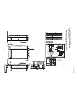
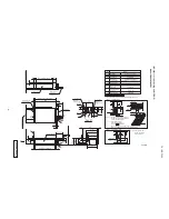
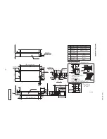
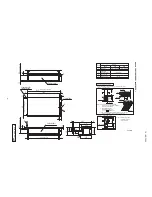
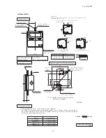
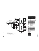
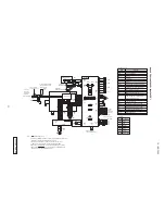
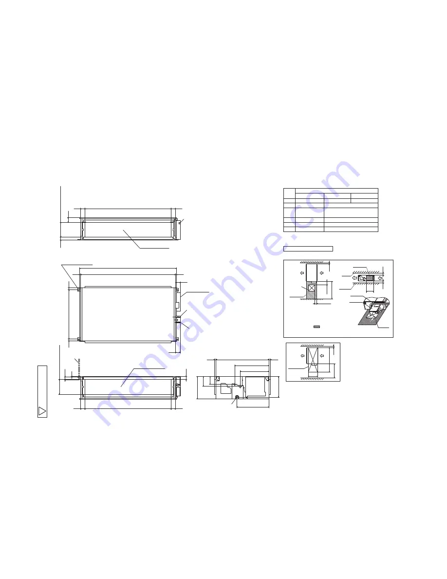
Models FDU1800FKXZE1,
2400FKXZE1
1600
85
50
250
(
Duct dimension
)
75
1450
(Duct dimension)
75
Unit:mm
A
Gas piping
B
Liquid piping
D
Hole for wiring
E
Suspension bolts
M10
Symbol
Content
φ
9.52(3/8")(Brazing)
φ
19.05(3/4")(Brazing)
φ
22.22(7/8")(Brazing)
F
Inspection hole
(450X450)
1500
Space for installation and service
150〜 200
100〜200
F
100
Slab
or more
20
20
or more
Note (a)
or more
or more
480
Ceiling
Note (b)
(Case 1) From side of unit
Select either of two cases to keep space for installation and services.
600
1900
100
or more
or more
(Case 2) From bottom of unit
Inspection
hole
880
Notes(1)The model name label
is attached on the lid
of the control box.
(b) Install refrigerant pipes,
not to cross marked area.
drain pipe,and wiring so as
Note (a)
out 2 fan units. For fan units maintenance,
Notes (a) There must not be obstacle to draw
refer to the service manual.
Pipe (c)
Fan unit
(c) The case that pipes are installed to upper (bottom) of fan unit,
keep space of 60mm or more to upper (bottom)of unit.
C
Drain piping
VP25(O.D.32)
486
579
539
133
165
349
379
893
25
25
1634
(Suspension bolts pitch)
17
17
31
831
31
79
(
Suspension bolts pitch
)
250
(
Duct dimension
)
75
1450
(Duct dimension)
75
Air supply duct
Return air duct
D
B
A
C
(Gravity drainage)
E
50
50
6
1800
2400
80
MODEL
Control box
suspension bolt
Hanger plate for
A
P
JG
0
0
0
Z
2
9
7

