-
134
-
'10 • KX-SM-148
Caution
A
B
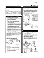
[Figure 1]
[Figure 2]
Hook
Screw
PJA012D783
30
30
A
B
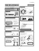
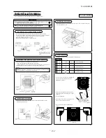
PANEL INSTALLATION MANUAL
Please read this manual together with the indoor unit’s installation manual.
WARNING
Fasten the wiring to the terminal securely and hold the cable securely so as not
to apply unexpected stress on the terminal.
Loose connection or hold will cause abnormal heat generation or fire.
�
Make sure the power supply is turned off when electric wiring work.
Otherwise, electric shock, malfunction and improper running may occur.
�
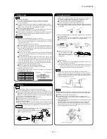
1
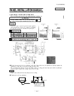
Checking the indoor unit installation position
• Read this manual together with the air conditioner installation manual carefully.
• Check if the gap between the ceiling plane and the indoor unit is correct by inserting the
level gauge into the air outlet port of the indoor unit. (See below drawing)
• Adjust the installation elevation if necessary.
• Remove the level gauge before you attach the panel.
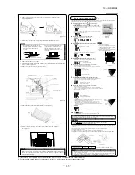
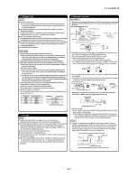
• Unscrew the screw from the corner area, pull the corner panel toward the direction
indicated by the arrow mark.
• First insert the part “a” of a corner panel into the part “A” of the cover panel, engage two
hooks and tighten the screw.
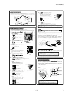
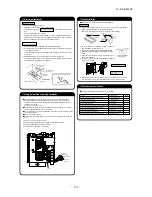
1. Take note that there is an orientation to install the panel.
• Attach the panel with the orientation shown on the below.
• Align the “PIPE SIDE” mark (on the panel) with the refrigerant pipes on the indoor unit.
2. The intake grille can also be attached in a rotated position by 90 degrees.
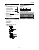
1. Screw in two bolts out of the four supplied with
the panel by about slightly less than 5mm.
(
�
mark
A B
) [Figure 1]
2. Attach the hook supplied with the panel to the
main body with the hook fixing screw (1 screw).
[Figure 2]
3. Open the intake grille.
4. Please remove the screw of a corner panel and
remove a corner panel. (four places)
5. A panel is hooked on two bolts (
�
mark
A B
).
[Figure 3]
· In case the orientation of the panel is not correct, it will lead to air leakage and also
it is not possible to connect the louver motor wiring.
2
Orientation of the panel and return air grille installation
3
Removing a corner panel
4
Attaching a corner panel
5
Panel installation
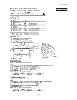
Accessories
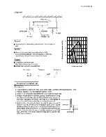
Use level gauges
as reference, adjust
the bottom to the
face of the indoor
unit.
Use level gauges
as reference, adjust
the bottom to the
face of the indoor
unit.
When the ceiling panel comes below
the T bar, align the bottom of the level
gauge to the lower face of the ceiling
panel.
Diffuser
Ceiling panel
Ceiling panel
Intake grille
Refrigerant
pipes side
Control box
Drain pipe side
Screw
Screw
Hook
Corner
panel
T-bar
T-bar
Level gauge
(insulation)
Level gauge
(insulation)
Diffuser
Louver motor
connector
• Install the panel on the unit after completing the electrical wiring.
1
2
3
4
5
Hook
Chain
Screw
Screw
Screw
1 piece
2 pieces
4 pieces
1 piece
2 pieces
For fixing temporarily
For hoisting the panel
For attaching a hook
For attaching a chain
[Figure 3]
To be continued on the other side.
PJA012D783
Summary of Contents for KX6 series
Page 106: ... 104 10 KX SM 148 Models FDC335KXE6M FDCS335KXE6M PCB003Z185 ...
Page 108: ... 106 10 KX SM 148 2 Ceiling cassette 4 way Compact type FDTC Models All moddels A PJA003Z341 ...
Page 111: ... 109 10 KX SM 148 b Duct type Models All models PJC001Z281 ...
Page 112: ... 110 10 KX SM 148 5 Ceiling cassette 1 way type FDTS Model FDTS45KXE6D B PJC001Z195 ...
Page 113: ... 111 10 KX SM 148 Model FDTS71KXE6D B PJC001Z196 ...
Page 116: ... 114 10 KX SM 148 Models FDUM112KXE6D 140KXE6D C PJR002Z259 ...
Page 120: ... 118 10 KX SM 148 Model FDK71KXE6D PHA001Z030 ...
Page 122: ... 120 10 KX SM 148 Models FDE71KXE6D 112KXE6D 140KXE6D C PFA003Z827 ...
Page 123: ... 121 10 KX SM 148 12 Floor standing 2 way type FDFW Models All models A PGF000Z004 ...
Page 127: ... 125 10 KX SM 148 5 APPLICATION DATA 5 1 Installation of indoor unit PJF012D016 a ...
Page 128: ... 126 10 KX SM 148 PJF012D016 A 1 Ceiling cassette 4way type FDT ...
Page 129: ... 127 10 KX SM 148 ...
Page 130: ... 128 10 KX SM 148 ...
Page 141: ... 139 10 KX SM 148 4 Ceiling cassette 1way compact type FDTQ PJC012D121 ...
Page 142: ... 140 10 KX SM 148 ...
Page 143: ... 141 10 KX SM 148 ...
Page 146: ... 144 10 KX SM 148 2 Parts Models QR PNA 14W ER QR PNB 14W ER PJC012D102 h ...
Page 148: ... 146 10 KX SM 148 ...
Page 149: ... 147 10 KX SM 148 5 Ceiling cassette 1way type FDTS PJC012D016 ...
Page 150: ... 148 10 KX SM 148 ...
Page 151: ... 149 10 KX SM 148 ...
Page 152: ... 150 10 KX SM 148 6 Duct connected High static pressure type FDU PJD012D053 ...
Page 153: ... 151 10 KX SM 148 ...
Page 154: ... 152 10 KX SM 148 ...
Page 158: ... 156 10 KX SM 148 8 Duct connected thin Low static pressure type FDUT PJM012D032 B ...
Page 159: ... 157 10 KX SM 148 ...
Page 160: ... 158 10 KX SM 148 ...
Page 161: ... 159 10 KX SM 148 9 Duct connected Compact and Flexible type FDUH PJC012D207 a ...
Page 163: ... 161 10 KX SM 148 ...
Page 164: ... 162 10 KX SM 148 PHA012D039 10 Wall mounted type FDK ...
Page 165: ... 163 10 KX SM 148 ...
Page 166: ... 164 10 KX SM 148 ...
Page 170: ... 168 10 KX SM 148 PGF012D004 12 Floor standing 2 way type FDFW ...
Page 171: ... 169 10 KX SM 148 ...
Page 173: ... 171 10 KX SM 148 13 Outdoor air processing unit type FDU F PJD012D059 ...
Page 174: ... 172 10 KX SM 148 ...
Page 175: ... 173 10 KX SM 148 ...
Page 184: ... 10 KX SM 148 182 ...
Page 212: ... 210 10 KX SM 148 2 model type DIS model type HEAD ...
Page 213: ... 211 10 KX SM 148 2 2 ...
Page 214: ... 212 10 KX SM 148 2 2 2 2 2 ...

