-
154
-
'10 • KX-SM-148
⑦
Drain pipe (continued)
⑥
Refrigerant pipe
⑦
Drain pipe
Caution
●
Use the new refrigerant pipe.
When re-using the existing pipe system for R22 or R407C, pay attention to the following items.
・
Change the flare nuts with the attached ones (JIS category 2), and reprocess the flare parts.
・
Do not use thin-walled pipes.
●
Use phosphorus deoxidized copper alloy seamless pipe (C1220T specified in JIS H3300) for refrigeration pipe installation.
In addition, make sure there is no damage both inside and outside of the pipe, and no harmful
substances such as sulfur, oxide, dust or a contaminant stuck on the pipes.
●
Do not use any refrigerant other than R410A.
Using other refrigerant except R410A (R22 etc.) may degrade inside refrigeration oil. And air getting into
refrigeration circuit may cause over-pressure and resultant it may result in bursting, etc.
●
Store the copper pipes indoors and seal the both end of them until they are brazed in order to avoid any dust, dirt or
water getting into pipe. Otherwise it will cause degradation of refrigeration oil and compressor breakdown, etc.
●
Use special tools for R410 refrigerant.
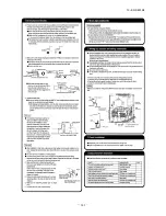
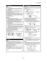
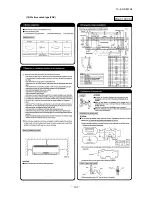
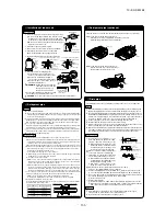
Piping work
When conducting piping work, make sure to allow the pipes
to be aligned in a straight line for at least 250 mm, as shown
in the left illustration. (This is necessary for the drain pump
to function)
Work procedure
1. Remove the flare nut and blind flanges on the pipe of the indoor unit.
※
Make sure to loosen the flare nut with holding the nut on pipe side with a spanner and giving torque to the
nut with another spanner in order to avoid unexpected stress to the copper pipe, and then remove them.
(Gas may come out at this time, but it is not abnormal.)
●
Pay attention whether the flare nut pops out. (as the indoor unit is sometimes pressured.)
2. Make a flare on liquid pipe and gas pipe, and connect the refrigeration pipes on the indoor unit.
※
Bend the pipe with as big radius as possible and do not bend the pipe repeatedly. In addition,
do not twist and crush the pipes.
※
Do a flare connection as follows:
●
Make sure to loosen the flare nut with holding the nut on pipe side with a spanner and giving
torque to the nut with another spanner in order to avoid unexpected stress to the copper
pipe, and then remove them.
●
When fastening the flare nut, align the refrigeration pipe with the center of flare nut, screw
the nut for 3-4 times by hand and then tighten it by spanner with the specified torque
mentioned in the table below. Make sure to hold the pipe on the indoor unit securely by a
spanner when tightening the nut in order to avoid unexpected stress on the copper pipe.
3. Cover the flare connection part of the indoor unit with attached insulation material after a gas
leakage inspection, and tighten both ends with attached straps.
●
Make sure to insulate both gas pipes and liquid pipes completely.
※
Incomplete insulation may cause dew condensation or water dropping.
4. Refrigerant is charged in the outdoor unit.
As for the additional refrigerant charge for the indoor unit and piping, refer to the installation
manual attached to the outdoor unit.
Caution
●
Install the drain pipe according to the installation manual in order to drain properly.
Imperfection in draining may cause flood indoors and wetting the household goods, etc.
●
Do not put the drain pipe directly into the ditch where toxic gas such as sulfur, the other harmful and
inflammable gas is generated. Toxic gas would flow into the room and it would cause serious
damage to user’s health and safety (some poisoning or deficiency of oxygen). In addition, it may
cause corrosion of heat exchanger and bad smell.
●
Connect the pipe securely to avoid water leakage from the joint.
●
Insulate the pipe properly to avoid condensation drop.
●
Check if the water can flow out properly from both the drain outlet on the indoor unit and the end
of the drain pipe after installation.
●
Make sure to make descending slope of greater than 1/100 and do not make up-down bend and/or trap
in the midway. In addition, do not put air vent on the drain pipe. Check if water is drained out properly from
the pipe during commissioning. Also, keep sufficient space for inspection and maintenance.
Work procedure
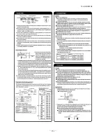
1. Make sure to insert the drain hose (the end mode of soft PVC) to the end of the step part of drain
socket.
Attach the hose clamp to the drain hose around 10mm from the end, and fasten the screw within
5mm left to the nut.
●
Do not apply adhesives on this end.
●
Do not use acetone-based adhesives to connect to the drain socket.
Pipe diameter
Tightening torque N·m
φ
6.35
φ
9.52
φ
12.7
φ
15.88
φ
19.05
14 to 18
34 to 42
49 to 61
68 to 82
100 to 120
Strap (Accessory)
Pipe cover (Accessory)
The thickness of insulation should be 20mm or more.
2. Prepare a joint for connecting VP-20 pipe, adhere and connect the joint to the drain hose
(the end made of rigid PVC), and adhere and connect VP-20 pipe (prepare on site).
※
As for drain pipe, apply VP-20 made of rigid PVC which is on the market.
●
Make sure that the adhesive will not get into the supplied drain hose.
It may cause the flexible part broken after the adhesive is dried up and gets rigid.
●
The flexible drain hose is intended to absorb a small difference at installation of the unit
or drain pipes. Intentional bending, expanding may cause the flexible hose broken and
water leakage.
3. Make sure to make descending slope of greater than 1/100 and do not make up-down bend
and/or trap in the midway.
●
Pay attention not to give stress on the pipe on the indoor unit side, and support and fix the
pipe as close place to the unit as possible when connecting the drain pipe.
●
Do not set up air vent.
●
When sharing a drain pipe for more than
one unit, lay the main pipe 100mm
below the drain outlet of the unit. In
addition, select VP-30 or bigger size for
main drain pipe.
⑦
Drain pipe (continued)
⑩
Tap selection on blower unit (when the high peformance filter is used)
⑧
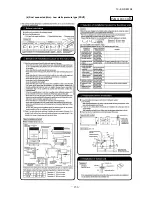
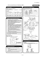
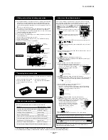
Wiring-out position and wiring connection
⑨
Check list after installation
Drain pump operation
○
In case electrical wiring work finished
Drain pump can be operated by remote controller (wired).
For the operation method, refer to Operation for drain pump in the installation manual for wiring
work.
○
In case electrical wiring work not finished
Drain pump will run continuously when the dip switch“SW7-1” on the indoor unit PCB is turned ON, the Connec-
tor CNB is disconnected, and then the power supply (230VAC on the terminal block
①
and
②
) is turned ON.
Make sure to turn OFF “SW7-1” and reconnect the Connector CNB after the test.
●
Electrical installation work must be performed according to the installation manual by an
electrical installation service provider qualified by a power provider of the country, and be
executed according to the technical standards and other regulations applicable to electrical
installation in the country.
Be sure to use an exclusive circuit.
●
Use specified cord, fasten the wiring to the terminal securely, and hold the cord securely in
order not to apply unexpected stress on the terminal.
●
Do not put both power source line and signal line on the same route. It may cause miscommu-
nication and malfunction.
●
Be sure to do D type earth work.
●
For the details of electrical wiring work, see attached instruction manual for electrical wiring
work.
1. Remove a lid of the control box (2 screws).
2. Hold each wiring inside the unit and fasten them to terminal block securely.
3. Fix the wiring with clamps.
4. Install the removed parts back to original place.
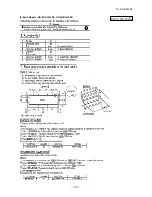
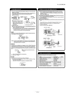
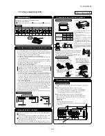
Following table shows the maximum external static pressure for models adapted to the fan setting
speed (Hi, UHi). Select at site the fan setting speed according to the external static pressure .
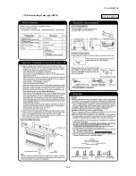
⑤
Duct Work (continued)
●
When placing the inlet port to carry out suction from the bottom side, use the following
procedure to replace the suction duct joint and the bottom plate.
●
Remove the screws which fasten the
●
Replace the removed bottom plate
bottom plate and the duct joint on the
and duct joint.
inlet port side of the unit.
●
Fit the duct join with a screw; fit the bottom plate.
●
Make sure to insulate the duct to prevent dewing on it.
④
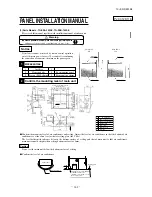
Install the specific blowout duct in a location where the air will
circulate to the entire room.
●
The duct connection is specific to the 200 circular duct.
●
Conduct the installation of the specific blowout hole and the
connection of the duct before attaching them to the ceiling.
●
Insulate the area where the duct is secured by a band for
dew condensation prevention.
⑤
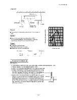
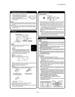
Make sure provide an inspection hole on the ceiling. It is indispensable to service elecric
equipment, motor, functional components and cleaning of heat exchanger.
①
If a duct is not provided at the suction side but it is substituted with the space over the ceiling,
humidity in the space will increase by the influence of capacity of ventilation fan, strength of
wind blowing against the out door air louver, weather (rainy day) and others.
a)Moisture in air is likely to condense over the external plates of the unit and to drip on the
ceiling. Unit should be operated under the conditions as listed in the above table and within
the limitation of wind volume. When the building is a concrete structure, especially imme-
diately after the construction, humidity tends to rise even if the space over the ceiling is not
substituted in place of a duct. In such occasion, it is necessary to insulate the entire unit with
glass wool (25mm). (Use a wire net or equivalent to hold the glass wool in place.)
b)It may run out the allowable limit of unit operation (Example: When outdoor air temperature
is 35°C DB, suction air temperature is 27°C WB) and it could result in such troubles as
compressor overload, etc..
c)There is a possibility that the blow air volume may exceed the allowable range of operation
due to the capacity of ventilation fan or strength of wind blowing against external air louver
so that drainage from be heat exchanger may fall to reach the drain pan but leak outside
(Example: drip on to the ceiling) with consequential water leakage in the room.
②
If vibration damping is not conducted between the unit and the duct, and between the unit and
the slab, vibration will be transmitted to the duct and vibration noise may occur. Also, vibration
may be transmitted from the unit to the slab. Vibration damping must be performed.
Notice
A specific cover plate is available when changing the 4 spot to the 3 spot, or when changing the
3 spot to the 2 spot.
Note: Do not change from 2 spot to 1 spot.
Connecting the air intake/vent ducts
①
Fresh Air Intake
[for air intake duct only]
○
Use the side fresh air intake hole, or supply
through a part of the suction duct.
[for simultaneous air intake/vent]
○
Intake air through the suction duct.
(the side cannot be used)
②
Air Vent
○
Use the side air vent hole.
(always use together with the air intake)
○
Use the duct flange for the air intake/vent (sold separately; for 125 circular duct connection),
and connect the 125 circular duct (tighten with band).
○
Insulate the duct to protect it from dew condensation.
Drain hose
600 max.
Joint for VP-20 (Prepare on site)
290~325
100 or less
unit (mm)
P.C. board
Fuse
For drain motor
connector CNR (blue)
Multi type
22~56
71, 90, 140
Single type
50
60,71,125,140
Fan
Speed
Hi
60/60
60/60
UHi
85/90
85/100
112
50/60Hz
Unit:Pa
100
60/60
90/100
CAUTION
If the external static pressure is 60Pa or less, do not set the fan speed to UHi.
If UHi setting is done, air outlet speed from indoor unit will increase and waterdrop
may be blown out and wet the ceiling or the furniture.
Secure with a band, etc.
Blowout
duct
Air conditioner main unit
Ceiling suriace
Suction grille
(Locality)
Suction grille
(option)
Suction hole
(marketed item)
(with air filter)
Inspection hole
Suction duct
(marketed item)
Blow outlet
Blowout duct
(optional or marketed item)
Bad example of duct work
For ventilation
Louver to
outdoor air
(Pipe side)
(Pipe side)
Side fresh air intake hole
Air vent hole
Fresh air intake through the
suction duct
Fresh air intake through the
suction duct
(Pipe side)
Air vent hole
Fresh air intake through the
suction duct
Refrigerant pipe
250mm
(Section where attached
in a straight line)
Drain socket
Drain hose
(Accessory)
Pipe cover (big) (For insulation)
(Accessory)
VP20 joint (Prepare on site)
VP20
(Prepare on site)
Pipe cover (small)
(For insulation) (Accessory)
Unit
Clamp (Accessory)
Pipe cover (small)
(For insulation)
(Prepare on site)
Adhesion
Insert water supply hose
for 20mm ~ 30mm to
supply water.
(Insert hose facing
toward bottom.)
Attached drain hose clamp
Drain
piping
Main
unit
Drain situation can be checked with transparent socket.
If the electrical work has not been completed, connect a convex
joint in the drain pipe connection to provide a water inlet.
Then, check if water leaks from the piping system and that
drain flows through the drain pipe normally.
Pour water into a convex joint
Remove grommet
Make sure to Install
it back after test.
Connecting port of top drain pipe
Insulating material
Rubber stopper (to be removed)
Connecting port of bottom drain pipes
Standard hard polyvinyl
chloride pipes
Bad example of duct work
(
)
●
Check the following items after all installation work completed.
Check if
Expected trouble
Check
The indoor and outdoor units are fixed securely?
Falling, vibration, noise
Inspection for leakage is done?
Insufficient capacity
Insulation work is properly done?
Water leakage
Water is drained properly?
Water leakage
Supply voltage is same as mentioned in the model name plate? PCB burnt out, not working at all
There is mis-wiring or mis-connection of piping?
PCB burnt out, not working at all
Earth wiring is connected properly?
Electric shock
Cable size comply with specified size?
PCB burnt out, not working at all
Any obstacle blocks airflow on air inlet and outlet?
Insufficient capacity
Descending slope greater than 1/100
As wide as possible
(about100mm)
Insulation material
Supporting metal
Descending slope greater than 1/100
Air vent
No bump
No trap
Not touching the water
Trapped air will
generate noises.
VP-30 or bigger
1.5m~2m
CN CNS
CNV
CNT2
CNN
CNH
CNZ
CNA
CND
CNK2
CNK1
CNV
CNS
CNI
CNT2
CNN CNH
CNZ
CN
A
CN
D
CNK
2
CNK1
Single unit wiring connection
Multi unit wiring connection
Power source
line clamp
Inner/outer
connecting line
Remote controller line
Earth
Power source side
terminal block
Signal side
terminal block
Signal side
terminal block
Indoor power source line
Power source side
terminal block
Remote controller line
Power source
line clamp
Signal line (Shielded cord)
Earth
Earth (Shielded cord)
Drain socket
Metal plate
10mm
Hose clamp
Fasten the screw within
5 mm left to the nut.
Drain hose
Drain socket
Drain hose
Stage difflernce part
4. Insulate the drain pipe.
●
Be sure to insulate the drain socket and rigid PVC pipe installed indoors otherwise it may
cause dew condensation and water leakage.
※
After drainage test implementation, cover the drain socket part with pipe cover (small size), then
use the pipe cover (big size) to cover the pipe cover (small size), clamps and part of the drain
hose, and fix and wrap it with tapes to wrap and make joint part gapless.
Drain up
●
The position for drain pipe outlet can be raised up to 600mm above the ceiling. Use elbows for
installation to avoid obstacles inside ceiling. If the horizontal drain pipe is too long before vertical pipe,
the backflow of water will increase when the unit is stopped, and it may cause overflow of water from the
drain pan on the indoor unit. In order to avoid overflow, keep the horizontal pipe length and offset of the
pipe within the limit shown in the figure below.
Otherwise, the construction point makes it same as drain pipe construction.
Drain test
1. Conduct a drain test after completion of the electrical work.
2. During the trail, make sure that drain flows properly through the piping and that no water
leaks from connections.
3. In case of a new building, conduct the test before it is furnished with the ceiling.
4. Be sure to conduct this test even when the unit is installed in the heating season.
Procedures
1. Supply about 1000 cc of water to the unit through the air outlet by using a feed water pump.
2. Check the drain while cooling operation.
Outline of bottom drain piping work
●
If the bottom drain piping can be done with a
descending gradient (1/50-1/100), it is possible to
connect the pipes as shown in the drawing below.
Uncoupling the drain motor connector
●
Uncouple the connector CNR for the drain motor
as illustrated in the drawing on the right.
Note: If the unit is run with the connector coupled,
drain water will be discharged from the upper drain
pipe joint, causing a water leak.
Summary of Contents for KX6 series
Page 106: ... 104 10 KX SM 148 Models FDC335KXE6M FDCS335KXE6M PCB003Z185 ...
Page 108: ... 106 10 KX SM 148 2 Ceiling cassette 4 way Compact type FDTC Models All moddels A PJA003Z341 ...
Page 111: ... 109 10 KX SM 148 b Duct type Models All models PJC001Z281 ...
Page 112: ... 110 10 KX SM 148 5 Ceiling cassette 1 way type FDTS Model FDTS45KXE6D B PJC001Z195 ...
Page 113: ... 111 10 KX SM 148 Model FDTS71KXE6D B PJC001Z196 ...
Page 116: ... 114 10 KX SM 148 Models FDUM112KXE6D 140KXE6D C PJR002Z259 ...
Page 120: ... 118 10 KX SM 148 Model FDK71KXE6D PHA001Z030 ...
Page 122: ... 120 10 KX SM 148 Models FDE71KXE6D 112KXE6D 140KXE6D C PFA003Z827 ...
Page 123: ... 121 10 KX SM 148 12 Floor standing 2 way type FDFW Models All models A PGF000Z004 ...
Page 127: ... 125 10 KX SM 148 5 APPLICATION DATA 5 1 Installation of indoor unit PJF012D016 a ...
Page 128: ... 126 10 KX SM 148 PJF012D016 A 1 Ceiling cassette 4way type FDT ...
Page 129: ... 127 10 KX SM 148 ...
Page 130: ... 128 10 KX SM 148 ...
Page 141: ... 139 10 KX SM 148 4 Ceiling cassette 1way compact type FDTQ PJC012D121 ...
Page 142: ... 140 10 KX SM 148 ...
Page 143: ... 141 10 KX SM 148 ...
Page 146: ... 144 10 KX SM 148 2 Parts Models QR PNA 14W ER QR PNB 14W ER PJC012D102 h ...
Page 148: ... 146 10 KX SM 148 ...
Page 149: ... 147 10 KX SM 148 5 Ceiling cassette 1way type FDTS PJC012D016 ...
Page 150: ... 148 10 KX SM 148 ...
Page 151: ... 149 10 KX SM 148 ...
Page 152: ... 150 10 KX SM 148 6 Duct connected High static pressure type FDU PJD012D053 ...
Page 153: ... 151 10 KX SM 148 ...
Page 154: ... 152 10 KX SM 148 ...
Page 158: ... 156 10 KX SM 148 8 Duct connected thin Low static pressure type FDUT PJM012D032 B ...
Page 159: ... 157 10 KX SM 148 ...
Page 160: ... 158 10 KX SM 148 ...
Page 161: ... 159 10 KX SM 148 9 Duct connected Compact and Flexible type FDUH PJC012D207 a ...
Page 163: ... 161 10 KX SM 148 ...
Page 164: ... 162 10 KX SM 148 PHA012D039 10 Wall mounted type FDK ...
Page 165: ... 163 10 KX SM 148 ...
Page 166: ... 164 10 KX SM 148 ...
Page 170: ... 168 10 KX SM 148 PGF012D004 12 Floor standing 2 way type FDFW ...
Page 171: ... 169 10 KX SM 148 ...
Page 173: ... 171 10 KX SM 148 13 Outdoor air processing unit type FDU F PJD012D059 ...
Page 174: ... 172 10 KX SM 148 ...
Page 175: ... 173 10 KX SM 148 ...
Page 184: ... 10 KX SM 148 182 ...
Page 212: ... 210 10 KX SM 148 2 model type DIS model type HEAD ...
Page 213: ... 211 10 KX SM 148 2 2 ...
Page 214: ... 212 10 KX SM 148 2 2 2 2 2 ...


