background image

Error code

Remote controller:
7-segment display:

LED

Green

Red

Indoor

Outdoor

Content

– 

92

 –

'10 • KX-SM-148

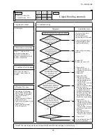
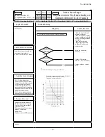
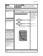
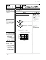
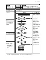
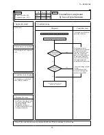
E56

E56-1

Power transitor temperature 


thermistor anomaly (Tho-P1)

Keeps flashing

Stays Off

Keeps flashing 1 time flash

1. Applicable model

5. Troubleshooting

Outdoor unit

Diagnosis

Countermeasure

Is the 

connector of  

thermistor connected 

properly OK 

Are the 

characteristics of 

thermistor OK?

Temperature-resistance characteristics of power transistor 

temperature thermistor (Tho-P1)

Save data for 30 minutes before stopping in Mente PC 

YES 

NO 

NO 

YES 

Temperature (°C) 

Power transistor thermistor 

resistance (kΩ)


20 

40 

60 

80 

100 

120 

140 

160 

180 

200 

20 

40 

60 

80 

100 

120 

140 

*1 Check several times to prove any poor connection

*1

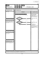
Check and save the data of 

operating condition.

Check the conditions 

whether it occurs 

immediately after the 

power on or during 

operation or stopping.

Check the sensed value.

Compare the temperature 

of Mente PC data with 

actual measured value
Insert the connector 

securely

Replace power transistor 

temperature thermistor 

(Tho-P1).

Replace outdoor control 

PCB.

2. Error detection method

Detection of anomalously low 

temperature (resistance) of 

Tho-P1

3. 

Condition of error displayed


When the outdoor air temperature 

is above 0ºC, if -10ºC or lower 

is detected for 20 seconds 

continuously within 10 minutes 

to 10 minutes 30 seconds after 

compressor ON, compressor stops. 

When the compressor is restarted 

automatically after 3-minutes 

delay, if this anomaly occurs 3 

times within 40 minutes

4. Presumable cause

• 

Broken thermistor harness or 

the internal wire of sensing 

section (Check the molded 

section as well) 

• 

Disconnection of thermistor 

harness connection 

(connector)

• 

Outdoor control PCB 

anomaly

Note:

Summary of Contents for KX6 series

Page 1: ... FDT112KXE6D FDT140KXE6D FDT160KXE6D FDTC22KXE6D FDTC28KXE6D FDTC36KXE6D FDTC45KXE6D FDTC56KXE6D FDU224KXE6D FDU280KXE6D FDTW28KXE6D FDTW45KXE6D FDTW56KXE6D FDTS45KXE6D FDTS71KXE6D FDTQ22KXE6D FDTQ28KXE6D FDTQ36KXE6D INDOOR UNIT KX6 series FDFW28KXE6D FDFW45KXE6D FDFW56KXE6D FDU500FKXE6D FDU850FKXE6D FDU1300FKXE6D FDU1800FKXE6D FDUM22KXE6D FDUM28KXE6D FDUM36KXE6D FDUM45KXE6D FDUM56KXE6D FDUM71KXE6...

Page 2: ...ssette 4 way type FDT 126 2 Ceiling cassette 4 way compact type FDTC 131 3 Ceiling cassette 2 way type FDTW 136 4 Ceiling cassette 1 way compact type FDTQ 139 5 Ceiling cassette 1 way type FDTS 147 6 Duct connected High static pressure type FDU 150 7 Duct connected Low Middle static pressure type FDUM 153 8 Duct connected thin Low static pressure type FDUT 156 9 Duct connected Compact and Flexible...

Page 3: ...iated Pull the cover downward to open it All displays are described in the liguid crystal display for explanation The figure below shows the remote control with the cover opened Installation of remote control DO NOT install it on the following places in order to avoid malfunction 1 Places exposed to direct sunlight 2 Places near heat devices 3 High humidity places 4 Hot surface or cold surface eno...

Page 4: ... to Hi 2 Lower limit of tap down for the indoor air volume is Lo tap 2 If the suction air temperature exceeds the setting temperature 3 C or more during defrosting operation the indoor fan tap is raised by one tap That tap is retained for 3 minutes after changing the indoor fan tap Note 1 Upper limit of tap up for the indoor air volume is the setting air volume 3 If the thermostat OFF is establish...

Page 5: ...ormed at the start of the defrost control a Control 1 When the indoor heat exchanger temperature detected with ThI R1 or R2 drops to 35 C or lower indoor fan is changed to the lower tap at each setting 2 During the hot keep operation the louver horizontal control signal is transmitted b Ending condition When the indoor fan is at the lower tap at each setting it returns to the set airflow volume as...

Page 6: ...thermostat OFF operation the louver keeps the level position In order to prevent the cold draft whether the auto swing switch is operated or not auto swing or louver stop The louver position display LCD continues to show the display which has been shown before entering this control c Louver free stop control When the louver free stop has been selected with the indoor function of wired remote contr...

Page 7: ... the indoor PCB is ON state it enters the mode of operation check drain pump test run It is ineffective prohibited to change the switch after turning power on b When the communication with the remote controller has been established within 60 seconds after turning power on by the dip switch SW7 1 ON it enters the operation check mode Unless the remote controller communication is established it ente...

Page 8: ...ating With the standard specification the compressor is turned ON OFF based on the setting temperature of thermostat However when the thermostat OFF is likely to occur earlier because the unit is installed in a condition that warm air tends to accumulate near the ceiling the setting can be changed by using the indoor function of wired remote controller Heating room temperature compensation Since t...

Page 9: ...the emergency stop E 63 signal is received from outdoor unit it is transmitted to the remote controller and makes stop d Fresh air processing operation input i If indoor unit controller receive fresh air processing operation signal 1 or fresh air processing stop signal from remote controller it output ON signal or OFF signal from CnD connector respectively 1 Operation switch ON at interlock settin...

Page 10: ...ncelled but weekly timer setting is changed to the holiday setting through all weekdays Operation mode Fan speed mode Room temperature setting Louver auto swing stop However the stop position position 4 is cancelled and is becomes the level position position 1 Remote control function items set with the remote controller function setting Indoor unit function items are stored in the inoor unit s mem...

Page 11: ... Super cooling coil electronic expansion valve EEVSC Opening Angle Control Fully closed Fully closed Fully closed Fully closed Fully closed Solenoid valve SV1 oil return 〇 〇 〇 Solenoid valve SV6 liquid injection return 〇 〇 〇 〇 〇 Solenoid valve SV11 gas bypass 〇 Crankcase heater CH 〇 〇 〇 〇 〇 〇 Note 1 It means 〇 ON OFF 〇 〇 ON or OFF 2 This shows the state of output when all indoor units are under th...

Page 12: ...or iii End conditions When all of the following conditions are satisfied It has elapsed 15 seconds after the start of this control Meaning of marks 52X1 52X2 Solenoid for compressor CM Compressor EEVH Heating electronic expansion valve EEVSC Subcooling coil electronic expansion valve SV6 Solenoid valve Liquid injection return ON 15 seconds 6 seconds Normal control Normal control Initial opening In...

Page 13: ...ponent operates according to the sequence shown below iii End conditions Meaning of marks CM Heating 15 seconds 3 minutes Initial speed Normal control Initial opening Cooling Any state Any state Any state FMo1 FMo2 20S EEVH EEVSC OFF Fully open Fully closed Fully closed Time Start conditions established OFF ON CM Compressor EEVH Heating electronic expansion valve FMo1 FMo2 Fan motor EEVSC Subcooli...

Page 14: ...shown below iii End conditions Note 1 It is fully closed till the end of 3 minute delay after the automatic reset Meaning of marks CM FMo1 FMo2 20S EEVH EEVSC ON Heating Cooling 15 seconds 3 minutes Initial opening Fully closed Time Start conditions established Normal control Initial speed Any state Any state Any state Fully closed OFF OFF Fully open CM Compressor EEVH Heating electronic expansion...

Page 15: ...ting till reaching the lower limit frequency after 4 way valve switching safeguard operation has elapsed lminute the target frequency is chnged to that of lminuted later from the lower limit frequency During this control the target frequency is increased at a rate of 5 Hz minute from the lower limit frequency Note The starting point of this control is the completion point of inverter start 10 Hz I...

Page 16: ...nutes from the lower limit frequency For 18 minutes after starting the starting point of this control is the completion point of inverter start 10 Hz From 18 minutes to 24 minutes it is increased at a rate of 5 Hz minute End conditions When either one of the following conditions is established a This frequency up control will end when the cumulative operation time after starting becomes 24 minutes...

Page 17: ... has detected HP 1 5 MPa for 1 minute continuously the fan speed is dropped by one tap Control range of fan speed is 1th 8th speeds iii When states under this control change from HP 3 3 MPa to HP 3 3 MPa the fan speed is changed preferentially to the followings After the change it returns to the normal control When the outdoor air temperature 30ºC it changes to 7th or higher speed When the outdoor...

Page 18: ... d Outdoor fan heating control The fan speed control is performed based on the low pressure detected with PSL during heating operation i Initial fan speed is 6th speed ii Speed is changed depending on the low pressure value When it is detected LP 0 75 MPa for 30 seconds continuously the fan speed is raised by 1 tap When it is 0 75 MPa LP 0 85 MPa the present fan speed is maintained When it is dete...

Page 19: ...r temperature C TA Outdoor air temperature C Fig 1 Cold region Standard Factory setting Defrost start zone 2 6 15 19 21 25 20 15 6 Without J15 Cold region specification With J15 SST Suction pressure saturated temperature C Fig 2 Cold region Standard Factory setting Defrost start zone 6 10 19 23 25 29 20 15 6 Without J15 Cold region specification With J15 2 End conditions Standard J14 is shorted a ...

Page 20: ...e of discharge pipe temperature 1 Compressor capacity control i Start conditions When all of following conditions are satisfied When the compressor is ON state When it detects the discharge pipe temperature sensed by Tho D1 is higher than 120ºC ii Control contents Whenever it detects the discharge pipe temperature is higher than 120ºC for 5 seconds the capacity is decreased iii End conditions When...

Page 21: ...l operation and the state of anomalous stop is kept ON even if the test run switch SW5 1 is turned OFF B Optional controls Functions of outdoor PCB connector CNS1 and CNZ1 CNS1 connector By changing the allocation of external input functions P07 X on the 7 segment following functions can be selected CNZ1 connector By changing the allocation of external input functions P06 X on the 7 segment follow...

Page 22: ...tion is desplayed on the LCD of remote controller and is transfered to optional centralised controller 4 When the control comand from remote controller is not accepted Under the condition of the system all stop status by external input Center is dispalyed See Item 5 mentioned below 5 CnS1 performs the following operations depending on the short circuit or open of the jumper wire J13 In case of pul...

Page 23: ...and ratio can be switched with the dip switches SW4 5 4 6 on the outdoor PCB SW4 5 SW4 6 demand switching 0 Open 1 Short circuit Factory default is open SW4 5 SW4 6 Compressor Out put 0 0 80 1 0 60 0 1 40 1 1 0 5 CnS1 performs the following operations depending on the short circuited or open of the jumper wire J13 In the case of pulse input the pulse width is 500ms or larger J13 Short circuit ON S...

Page 24: ...ment P04 instead of external input Demand control Compressor Hz is restricted with external input ON Demand ratio is set with Dip SW 4 5 and 4 6 2 step demand control Compressor Hz is restricted with external input ON Demand ratio is set with 7 segment P04 External input Demand input Invalid short circuit Normal Normal Normal Normal Invalid short circuit Valid release 2 step demand control Externa...

Page 25: ...excluded when the following invalid conditions are established For prevention of anomalous pressure rise at start For 30 seconds after either compressor has been turned ON During a special operation During the 4 way valve switching safeguard During the defrost control During the oil return control During the moved pump down control During the pump down control for removal of the unit Note Any cont...

Page 26: ...tactor 52X1 52X2 is ON d End conditions of outdoor fan snow protection control When folowing conditions are established i Snow protection control setting is invalid P02 0 or outdoor air temperature 5 C and external input of outdoor fan snow protection control OFF P07 5 and CnSlis opend ii Compressor ON iii During all stop by anomaly Valid Invalid Outdoor air temperature C 3 5 Outdoor air temperatu...

Page 27: ...nd CnG1 equipped with short circuit pin is shorted or opened so as to forcibly determined whether the indoor unit is operated for cooling or heating b If any operation mode other than the forcible mode is commanded from indoor unit the mode unmatch message is displayed on the remote controller or others and operation enters in the FAN mode SW3 7 CnG1 Operation ON Open Cooling only Close Heating on...

Page 28: ...blished both red LED and green LED on the outdoor PCB flash continuously 7 segment display shows PdS Channel 0 at the code display area iii During the pump down operation control the protective controls excluing low pressure protective control anomalous low pressure control and pressure ratio protection control and the error detection control are effective iv The sub cooling coil expansion valve E...

Page 29: ...ation and an anomalous stop occurs again no new anomalous data cannot be retained but former anomalous data are still retained unchanged If you press SW8 order of 1 the number changes 0 1 2 9 0 If you press SW9 order of 10 the number jumps to the leading code of each order of 10 Data display Cxx and setting value display Pxx are considered to be continuous Example Pressing SW9 at C07 it changes to...

Page 30: ...play of it changes to C00 However unless no button input is done for 10 seconds after change to C00 it changes to the display of automatically according to the precedence Display switching Special display is the display other than CXX When special display occurs Special display reset or button operation Button operation Button operation No operation for 10 seconds If the special display is reset i...

Page 31: ...5 90 1 C C11 Spare C12 Tho P1 Power transistor temperature CM1 L 5 136 1 C C13 Spare C14 Tho SC Sub cooling coil temperature 1 L 18 73 1 C C15 Tho H Sub cooling coil temperature 2 L 25 73 1 C C16 Tho S Suction pipe temperature L 25 73 1 C C17 Inverter secondary current 0 50 1A C18 CT1 CM1 current 0 50 1A C19 Spare C20 EEVH1 Heating expansion valve opening angle 0 500 1 pulse C21 Spare C22 EEVSC Su...

Page 32: ...or under is in the unit of 1 C C47 Suction pressure saturated temperature 50 30 0 1 C Range unable to display 10 C or under is in the unit of 1 C C48 Sub cooling coil temperature sensor 1 saturated pressure 0 68 4 15 0 01 MPa 0 is omitted in negative range 0 68 68 C49 Cooling sub cooling 0 50 0 1deg Subcooling temperature deg Discharge pressure saturation temperature Subcooling coil temperature 1 ...

Page 33: ...urrent cut 25 Inverter 1 startup failure 26 Inverter 1 communication error 27 Inverter 1 anomalous compressor induced voltage and torque 28 Inverter 1 power tansistor overheat 29 Inverter 1 rotor lock 30 Liquid flooding anomaly 31 Stop by restriction Outdoor operation mode heating cooling switching 40 Heating overload protection 41 Stopping time by compressor dilution ratio protection control Less...

Page 34: ...back error 0 3 1 Others C95 Spare C96 Data reset C97 Program Sub version 0 991 C98 Program POL version 0 00 9 99 0 01 C99 Auto feed display User setting P00 Spare P01 Operation priority selection 0 1 0 First push priority at shipping 1 Last push priorit P02 Outdoor unit fan snow protection control 0 1 2 3 0 Invalid Default 1 Valid Only the fan operates 2 Valid Fan heater ON 3 Valid Heater ON for 2...

Page 35: ... 0 Default 0 3 1 P27 Initial aperture correction value at the start of cooling indoor unit 0 Default 0 60 Pulse 20 P28 Enabling of 4 way selector noise reduction setting during defrosting 0 Default 0 1 P29 Spare setting 0 15 0 Default Spare setting Newsuper link setting P30 Superlink communication status 0 1 0 Previous superlink 1 New superlink P31 Automatic address setting start input 0 Factory d...

Page 36: ...r address Ascii 2 bytes 00 3F Indoor address 16 units Ascii 2 bytes 16 units 40 7F Indoor capacity 16 units Ascii 3 bytes 16 units 022 280 Outdoor unit composition Outdoor unit capacity data Remarks Single type Example 10HP S10 S Display with Horse Power of single type iv Error retention and monitoring data Code No Write contents Record data Data write range Unit of write Number of bytes Contents ...

Page 37: ...ted indoor units 0 127 1 unit 1 16 Capacity of connected indoor units 0 65535 2 17 Number of indoor units with thermostat ON 0 255 1 unit 1 18 Total capacity of indoor units with cooling thermostat ON 0 65535 2 19 Total capacity of indoor units with heating thermostat ON 0 65535 2 20 Operation mode 0 2 1 0 Stop 1 Cooling 2 Heating 21 Inverter CM1 actual operation frequency 0 255 1Hz 1 22 FMo1 Actu...

Page 38: ...al range 0 600min 10 hour PCB hardware input 48 External input 1 Bit0 63H1 0 Open 1 Short circuit Bit1 Spare 0 Open 1 Short circuit Bit2 CNS1 0 Open 1 Short circuit Bit3 CNS2 0 Open 1 Short circuit Bit4 CNG1 0 Open 1 Short circuit Bit5 CNG2 0 Open 1 Short circuit Bit6 Spare 0 Open 1 Short circuit Bit7 Spare 0 Open 1 Short circuit 49 Dip SW SW3 1 Bit0 SW3 1 0 OFF 1 ON Bit1 SW3 2 0 OFF 1 ON Bit2 SW3...

Page 39: ... 52X2 0 OFF 1 ON Bit1 20S 0 OFF 1 ON Bit2 CH1 0 OFF 1 ON Bit3 SV1 0 OFF 1 ON Bit4 SV6 0 OFF 1 ON Bit5 SV11 0 OFF 1 ON Bit6 Spare 0 OFF 1 ON Bit7 Spare FMC1 2 0 OFF 1 ON 55 Relay output 1 Bit0 Operation output CnH 0 OFF 1 ON Bit1 Error output CnY 0 OFF 1 ON Bit2 External output CnZ 0 OFF 1 ON Bit3 Spare 0 OFF 1 ON Bit4 Spare 0 OFF 1 ON Bit5 Spare 0 OFF 1 ON Bit6 Spare 0 OFF 1 ON Bit7 Spare 0 OFF 1 ...

Page 40: ... 83 Control status INV1 communication error counter cumulative 0 255 1 1 84 Spare Control status INV1 power transistor overheat error counter 0 4 1 1 85 Control status INV1 rotor lock error counter 0 127 1 1 Setting value display 86 Operation priority switching 0 1 1 0 First push priority 1 Last push priority 87 Outdoor fan snow protection control 0 1 2 3 1 0 Invalid 1 2 3 Valid 88 Outdoor fan sno...

Page 41: ...MPa 1 100 Heating setting 3 Judgment temperature 30 38 1 C 1 101 Check operation condition User can operate 1 0 only 0 1 1 Other 104 Override number 0 1 Indoor unit information 106 Registered indoor 1 8 operation mode 0 4 8 0 Auto 1 Humidifying 2 Cooling 3 Fan 4 Heating 107 Registered indoor 1 8 request Hz 0 255 1Hz 8 108 Registered indoor 1 8 answer Hz 0 255 1Hz 8 ...

Page 42: ...r wiring etc Is the failure related to any hardware parts SV main body coil capillary check valve sensor etc Is it a major component Compressor inverter PCB and outdoor DC fan motor Is it a failure of electrical component Error on indoor unit or outdoor unit Indoor unit Outdoor unit Is the remote controller connected Was the power supply reset after the error occurred Check and write down the mome...

Page 43: ...ment following check Be sure to check both fan motor 1 and 2 After completion of checking both fan motor 1 and 2 replace the anomalous fan motor Turn the power ON power circuit breaker ON and start operation with the test run SW Check between 1 and 2 of CNA2 on the control PCB to see if DC 15V is detected Be sure to wait for 3 minutes after turning the power circuit breaker off Disconnect the fan ...

Page 44: ...t exchanger temperature thermistor Tho R and subcooling coil temperature thermistor Tho SC H anomaly Thermistor wire breakage 79 E38 E38 Outdoor air temperature thermistor anomaly Tho A Thermistor wire breakage 80 E39 E39 1 Discharge pipe temperature thermistor anomaly Tho D1 Thermistor wire breakage 81 E40 E40 High pressure anomaly 63H1 1 activated System error 82 E41 E51 E41 E51 1 Power transist...

Page 45: ...efumidifying or heating operation from remote controller Note 1 Outdoor 35ºC Indoor 27ºCDB 19ºCWB It is normal This unit is designed to start in the soft start mode by detecting the compressor under dome temperature when it restart after power reset It is necessary to replace to higher capacity unit or to install additional unit Compressor refrigerant oil protective control at starting is activate...

Page 46: ...r heating operation from remote controller Note 1 Outdoor 7ºC Indoor 20ºC It is normal This unit is designed to start in the soft start mode by detecting the compressor under dome temperature when it restart after power reset It is necessary to replace to higher capacity unit or to install additional unit Compressor refrigerant oil protective control at starting is activated For the contents of co...

Page 47: ...ulation resistance may drop to a few MΩ because of refrigerant migrated in the compressor When the earth leakage breaker is activated at lower insulation resistance check the following points 6 hours after power ON check if the insulation resistance recovers to normal When power ON crankcase heater heat up compressor and evaporates the refrigerant migrated in the compressor Check if the earth leak...

Page 48: ...te looseness Prevent the vibration from transmitting to wall and etc by fixing pipes on the wall tightly or wrapping rubber cushion around the pipe which goes through the hole in the wall or applying other appropriate means Strength of ceiling wall floor etc may be insufficient Review the installation place or apply reinforcement to increase the strength Check for leaning of installed unit or inco...

Page 49: ...d flows through inside of piping of air conditioner It is likely to occur particularly during cooling or defrosting in the heating mode It is normal The noise vibration occurs when the refrigerant starts or stops flowing It is normal When the defrosting starts or stops during heating mode the refrigerant flow is reversed due to switching 4 way valve This causes a large change in pressure wich prod...

Page 50: ... Intrusion of air nitrogen etc In such case it is necessary to recover refrigerant vacuum dry and recharge refrigerant Since there could be many causes of noise vibration the above may not cover all In such case check the conditions when where how the noise vibration occurs according to following check points and ask our consultation Indoor outdoor unit Cooling heating fan mode Startup stop during...

Page 51: ...setting YES NO Does the louver link press LS till crick sound can be heard NO NO YES NO NO YES In cases of FDTW FDTS and FDTQ Does the louver operate when power on Note 1 LM Louver motor 2 LS Limit switch YES NO NO NO NO YES YES Operate after waiting for more than 1 minute It is normal if LM can be stopped by pressing LS two times In cases of FDT FDTC FDE and FDK Check the remote controller whethe...

Page 52: ... between of CNW0 OK Is DC5V detected between of CNW2 Is power supply to FM LM and etc OK Note 1 FDT and FDTC series F200 F201 Other than FDT and FDTC Fuse between wires 1 2 3 4 Other than FDT and FDTC series FDT and FDTC series Is DC18V or higher detected between Red Red CNW2 at the transformer secondary side Outdoor Noise filter PCB anomaly Replace it Wrong wiring or broken wires between outdoor ...

Page 53: ... secondary side Is DC18V detected between of CNW2 Disconnect the remote controller wires NO Is DC15V or higher detected between X Y of indoor unit terminal block Other than FDT and FDTC Series FDT and FDTC Series YES YES YES YES NO NO YES NO NO Correct it Replace wires Replace remote controller Indoor power PCB anomaly Replace it Indoor control PCB anomaly Replace it Replace transformer Indoor con...

Page 54: ...e noise filter PCB Connect wires correctly Indoor control PCB anomaly Replace it Indoor outdoor control PCB anomaly Replace it Remote controller anomaly Replace it Breakage of wires for remote controller Replace it Correct the connecting wires between indoor and outdoor units Outdoor control PCB anomaly Replace it Breakage of connecting wire Noise Indoor control PCB anomaly Replace it 2 Error dete...

Page 55: ...NO Isn t there any short circuit between phases of noise filter Isn t there any crack or damage on power transistor module or diode stack Isn t there any anomaly on reactor Replace noise filter Replace reactor Replace inverter PCB Replace fuse 2 Error detection method 3 Condition of error displayed 4 Presumable cause Fuse blown Noise filter anomaly Anomalous connection of wire between PCBs Indoor ...

Page 56: ...k Is The fuse on indoor control PCB OK Is AC18V or higher is detected between Red Red at secondary side of indoor transformer 1 Is DC10 11V between X Y at indoor control PCB side when removing remote controller Note 1 except FDT and FDTC Fuse blown Replace fuse Transformer anomaly Remote controller wire short circuited Remote controller anomaly Indoor control PCB anomaly Remote controller anomaly ...

Page 57: ...ected between L1 L2 L2 L3 L3 L1 respectively at outdoor terminal block Is AC220V detected between L N at indoor teminal block NO NO NO NO NO YES YES YES YES YES YES A WAIT Refer next page Indoor control PCB anomaly Replace it Indoor control PCB anomaly Replace it Remote controller anomaly Replace it Breakage of wires for remote controller Replace it Correct the connecting wires between indoor and ...

Page 58: ... Is there any anomaly on outdoor fan motor Once turn OFF the breaker and turn ON it again at 3 minute after power OFF Does it become normal Check inverter before replacement of 52C NO NO NO NO NO NO YES YES YES YES YES YES A B Normal Malfunction by temporary noise Refer next page Replace noise filter Connect the connecting wire properly Correct connection In case of breakage of wire replace it Out...

Page 59: ...r fuse Replace electrolytic capacitor Replace reactor Isn t there any short circuit between phases at input terminal of inverter PCB Isn t there any crack or damage on power transistor module or diode stack Isn t there any anomaly on reactor Isn t there any anomaly on electrolytic capacitor YES YES YES YES YES NO NO NO NO NO B 2 Error detection method 3 Condition of error displayed 4 Presumable ca...

Page 60: ...en X Y detected at remote controller terminal Is DC10V or higher between X Y wires detected when removing remote controller Are connecting wires between indoor and outdoor units connected properly Remote controller anomaly Remote controller anomaly Correct connecting wire Indoor control PCB anomaly 2 Error detection method 3 Condition of error displayed 4 Presumable cause Fuse blown Noise filter a...

Page 61: ...2 Does the remote controller displays Internal check ON even after 3 minutes Reset power supply 2 1 NO Malfunction by temporary noise Check peripheral environment Indoor control PCB anomaly Replace it Remote controller anomaly Replace it 2 Error detection method When normal communication between remote controller and indoor unit is interrupted for more than 2 minutes Detectable only with the remot...

Page 62: ...er supply is reset addresses will not be confirmed YES NO YES NO YES NO Review number of connected units Correct indoor unit address setting Implement test run Replace indoor control PCB Before replacement confirm whether the rotary switch for address setting is not damaged It was experienced that No 5 on rotary switch was not recognized 2 Error detection method More than 129 indoor units are conn...

Page 63: ...o E5 In both cases check signal wires between indoor outdoor units locally YES Is the outdoor unit address set on the indoor unit OK YES Is the LED on indoor control PCB OK YES Is protective fuse for the super link circuit blown NO Does E3 E5 occurs YES NO NO NO YES YES NO NO Temporary malfunction by noise Identify the source of noise and correct it Change to spare circuit Indoor control PCB anoma...

Page 64: ...s brakage of signal wires between indoor and outdoor units YES NO YES NO YES NO In case that indoor red LED flashes 2 times Repair signal wires Repair signal wires Go to the diagnosis of WAIT 1 Unit is normal Malfunction by temporary noise etc Outdoor control PCB anomaly Network communicaion circuit anomaly Replace it Unit is normal Malfunction by temporary noise etc 2 Error detection method When ...

Page 65: ...resistance characreristics of indoor heat exchanger temperature thermistor Thi R1 R2 R3 5kΩ at 25ºC Temperature ºC Insert the connector securely Replace thermistor Thi R Replace indoor control PCB 2 Error detection method Detection of anomalously low temperature resistance of Thi R1 R2 R3 3 Condition of error displayed If 50ºC or lower is detected for 5 seconds continuously compressor stops After ...

Page 66: ...al times to prove any poor connection 15 10 5 0 10 30 40 20 50 Temperature thermistor resistance k Ω Temperature C 5kΩ at 25 C Insert the connector securely Replace thermistor Thi A Replace indoor control PCB 2 Error detection method Detection of anomalously low temperature resistance of Thi A 3 Condition of error displayed If 50 C or lower is detected for 5 seconds continuously compressor stops A...

Page 67: ...the drain pipe slop OK NO YES NO YES NO NO Check float switch Check the connection of CNI If it is loose connect it securely Replace indoor control PCB Check optional equipment Correct setting to Humidifier drain motor interlock Indoor control PCB anomaly Replace it Check the wiring of drain motor Correct it Check drain motor 2 Error detection method Float switch is activated 3 Condition of error ...

Page 68: ...icable model 5 Troubleshooting All models Diagnosis Countermeasure Aren t more than 17 indoor units connected to one remote controller NO YES Remote controller anomaly Replace it Reduce to 16 or less units 2 Error detection method When it detects more than 17 of indoor units connected to one remote contorller 3 Condition of error displayed Same as above 4 Presumable cause Excessive number of indoo...

Page 69: ...rror displayed Same as above 4 Presumable cause Mistake in address setting for indoor unit Note Address setting method list Figures in are for Previous superlink models Models for new superlink protocol Models for Previous superlink protocol Indoor unit address setting Outdoor unit address setting Indoor unit address setting Outdoor unit address setting Indoor unit No SW Outdoor unit No SW Outdoor...

Page 70: ...ve foreign matter Replace the fan motor Check power supply voltage Replace fan motor and power PCB Replace fan motor If the anomaly persists after replacing the fan motor replace the indoor control PCB Malfunction by temporary noise 2 Error detection method Detected by rotation speed of indoor fan motor 3 Condition of error displayed When actual revolution speed of indoor fan motor drops to lower ...

Page 71: ...emove foreign matter Replace fan motor Replace fan motor and power PCB Replace fan motor If this anomaly persists after replacing the fan motor replace indoor control PCB Malfunction by temporary noise 2 Error detection method Detected by rotation speed of indoor fan motor 3 Condition of error displayed When actual revolution speed of indoor fan motor drops to lower than 200min 1 for 30 seconds co...

Page 72: ...㪜㪪 㪰㪜㪪 㪰㪜㪪 㪠㫊㩷㫋㪿㪼㩷㫇㫆㫎㪼㫉 㫊㫌㫉㪼㫃㫐㩷㫊㫌㫇㫇㫃㫀㪼㪻㩷㫋㫆㩷㫋㪿㪼㩷㫄㪸㫊㫋㪼㫉 㫀㫅㪻㫆㫆㫉㩷㫌㫅㫀㫋㩷㪖㩷㩷 㪠㫊㩷㫋㪿㪼㩷㪸㪻㪻㫉㪼㫊㫊 㫊㪼㫋㫋㫀㫅㪾㩷㪽㫆㫉㩷㫋㪿㪼㩷㫄㪸㫊㫋㪼㫉㩷㫀㫅㪻㫆㫆㫉 㫌㫅㫀㫋㩷㪺㫆㫉㫉㪼㪺㫋㪖㩷㩷 㪚㫆㫉㫉㪼㪺㫋㩷㫋㪿㪼㩷㪸㪻㪻㫉㪼㫊㫊㩷㫊㪼㫋㫋㫀㫅㪾㩷㫆㪽 㫋㪿㪼㩷㫄㪸㫊㫋㪼㫉㩷㫀㫅㪻㫆㫆㫉㩷㫌㫅㫀㫋 㪪㫌㫇㫇㫃㫐㩷㫋㪿㪼㩷㫇㫆㫎㪼㫉㩷㫋㫆㩷㫋㪿㪼㩷㫄㪸㫊㫋㪼㫉㩷 㫀㫅㪻㫆㫆㫉㩷㫌㫅㫀㫋 㪚㫆㫅㫅㪼㪺㫋㩷㫋㪿㪼㩷㫊㫌㫇㪼㫉㫃㫀㫅㫂㩷㫊㫀㪾㫅㪸㫃 㫎㫀㫉㪼㫊㩷㪺㫆㫉㫉㪼㪺㫋㫃㫐㪅㩷 㪠㫅㪻㫆㫆㫉㩷㪺㫆㫅㫋㫉㫆㫃㩷㪧㪚㪙㩷㪸㫅㫆㫄㪸㫃㫐 㸢㩷㪩㪼㫇㫃㪸㪺㪼㩷㫀㫋 㩿㪝㫀㫉㫊㫋㫃㫐㩷㫉㪼㫇㫃㪸㪺㪼㩷㪧㪚㪙㩷㫆㫅㩷㫋㪿㪼㩷 㫊㫃㪸㫍㪼㩷㫀㫅㪻㫆㫆㫉㩷㫌㫅㫀㫋㪅㩷㩷㪠㪽㩷㫀㫋㩷㫀㫊㩷㫅㫆㫋㩷㩷㩷㩷㩷 㫉㪼㪺㫆㫍㪼㫉㪼㪻㪃㩷㫉㪼㫇㫃㪸㪺...

Page 73: ...r displayed Same as above 4 Presumable cause Mistake in SW7 1 setting Due to forgetting to turn OFF SW7 1 after indoor operation check Note Indoor operation check drain pump check mode If the power is ON after SW7 1ON indoor operation check drain pump check mode can be established 1 When the communication between remote controller and indoor PCB is established 15 seconds after power ON it goes to ...

Page 74: ...alve in are for the model FDFW and FDK FDK FDFW series FDTC FDT series Remove foreign material Replace the fan motor Replace fan motor and power PCB Check power supply voltage Replace fan motor and power PCB Replace fan motor If the anomaly persists after replacing the fan motor replace the indoor control PCB Malfunction by temporary noise 2 Error detection method Detected by rotation speed of ind...

Page 75: ...y occurs again within 60 minutes after the initial detection 4 Presumable cause Anomalous connection of remote controller temperature thermistor Remote controller temperature thermistor anomaly Remote controller PCB anomaly Note After 10 seconds has elapsed since remote controller temperature thermistor was switched from invalid to valid E28 will not be displayed even if the thermistor harness is ...

Page 76: ...tween indoor and outdoor units correctly YES NO Is the voltage between L1 N at the terminal block on indoor unit AC220V NO Is the voltage between L1 L2 L2 L3 and L3 L1 at the terminal brock on outdoor unit AC220V respectively YES YES NO Correct the wiring Replace outdoor control PCB Disconnection or breakage of wire between indoor and outdoor unit Replace indoor unit PCB 2 Error detection method 3...

Page 77: ... address setting is not damaged It was experienced that No 5 on rotary switch was not recognized 2 Error detection method When the microcomputer of outdoor control PCB recognizes the dupplicated address No by scanning all adresses of outdoor units in the same superlink system 3 Condition of error displayed When duplicated outdoor unit address No exists in the same superlink system 4 Presumable cau...

Page 78: ...ether it occurs immediately after the power on or during operation or stopping It will be useful to persuade the customer why an improvement of power supply is required by showing these data Propose an improvement to the customer Check it as much as possible under the operating conditions for 30 minutes before error occurred Replace outdoor control PCB Wait and see without taking any action 2 Erro...

Page 79: ...insufficient or not Check the gas leakage Insert connector securely Check if the characteristics are correct by referring the characteristics chart of E39 And if necessary replace the discharge pipe temperature thermistor Check it as much as possible under the operating conditions for 30 minutes before error occurred Wait and see Continue to obtain data if possible Keep connecting the Mente PC Rep...

Page 80: ...he outdoor fan rotates Save data for 30 minutes before stopping in Mente PC Is the characteristics of Tho C1 OK NO NO NO NO NO NO NO YES YES YES YES YES YES YES Check and save the data of operating condition Check the ROM version Comfirmation of SV1 operation Correct the connection of refrigerant piping and or signal wiring properly Adjust refrigerant amount properly Replace SV1 Replace the coil o...

Page 81: ...and save the data of operating conditions Check the conditions whether it occurs immediately after the power on or during operation or stopping Check the sensed value Compare the temperature on Mente PC with actual measured value Insert the connector securely Replace Thermistor Tho SC Tho H Tho R Replace outdoor control PCB 2 Error detection method Detection of anomalously low temperature resistan...

Page 82: ... occurs immediately after the power on or during operation or stopping Check the sensed value Compare the temperature on Mente PC with actual measured value Insert the connector securely Replace thermistor Tho A Replace outdoor control PCB 2 Error detection method Detection of anomalously low temperature resistance of Tho A 3 Condition of error displayed If 30 C or lower is detected for 5 seconds ...

Page 83: ...of operating condition Check the conditions whether it occurs immediately after the power on or during operation or stopping Check the sensed value Compare the temperature on Mente PC with actual measured value Insert the connector securely Replace thermistor Tho D1 Replace outdoor control PCB 2 Error detection method Detection of anomalously low temperature resistance of Tho D1 3 Condition of err...

Page 84: ... high pressure sensor itself according to the troubleshooting procedure of E54 after retarting operation If the high pressure sensor PSH fails replace it If the connector is disconnected or the harness is broken correct it Also check whether the high pressure switch is properly mounted or not Open operation valve Check it as much as possible under the operating conditions for 30 minutes before err...

Page 85: ...see Continue to obain data if possible Keep connecting the Mente PC If the cooling fan does not run in spite of the operation ON range check the voltage at the connector of cooling fan If the 220 240V is detected repalce cooling fan motor If 0V is detected replace outdoor control PCB After checking the loose connection of connetor or breakage of harness replace inverter PCB Connect the connector o...

Page 86: ...separator If necessary replace the capillary tube and strainer as well Repair it according to the troubleshooting of E48 Replace inverter PCB or outdoor fan motor Check it as much as possible under the operating conditions for 30 minutes before error occurred Wait and see Continue to obain data if possible Keep connecting the Mente PC Replace power transistor module Replace inverter PCB Replace po...

Page 87: ...y of connected indoor units exceeds the limitation if tentative operation is required turn ON the dip switch SW5 4 on the outdoor control PCB However since this tentative solution could cause trouble be sure to correct it as soon as possible Signal wire may be connected to other outoor unit system Correct the signal wire Correct addresses Either one of addresses is wrong If the address corrected b...

Page 88: ...OFF ON OFF OFF OFF Check and save the data of operating conditions Replace inverter PCB or outdoor fan motor Check it as much as possible under the operating conditions for 30 minutes before error occurred Wait and see Continue to obain data if possible Keep connecting the Mente PC Check whether the harness is broken Check whether the connector is loose If there is problem correct it Disconnect th...

Page 89: ...aken because it is judged that the power rest is not done after changing address Correct signal line In case of automatic address setting signal line cannot be connected to other outdoor unit system Test run Replace outdoor control PCB Rotary switch anomaly Before replacement please confirm whether the rotary switch for address setting is not damaged It was experienced that No 5 on rotary switch w...

Page 90: ... Check and save the data of operating conditions Replace fan motor Replace inverter PCB or fan motor Check it as much as possible under the operating conditions for 30 minutes before error occurred Wait and see Continue to obain data if possible Keep connecting the Mente PC Replace fan motor Replace outdoor control PCB 2 Error detection method If 400min 1 or lower of the fan rotation command and t...

Page 91: ... at site according to the piping length instructed on the label pasted on the panel of the unit Check whether the service valves are open Correct the connection of low pressure sensor connector Replace low pressure sensor Replace outdoor control PCB Correct the connection of temperature thermistor connector of heat exchanger Replace temperature thermistor of heat exchanger at evaporator side Repla...

Page 92: ...thin 2 minutes to 2 minutes 20 seconds after compressor ON compressor stops When the compressor is restarted automatically after 3 minutes delay if this anomaly occurs 3 times within 40 minutes 4 Presumable cause Broken thermistor harness or the internal wire of sensing section Check the molded section as well Disconnection of thermistor harness connection connector Outdoor control PCB anomaly Not...

Page 93: ...ure measure by pressure gauge YES Output voltage V Output voltage V Check and save the data of operating conditions Check the conditions whether it occurs immediately after the power on or during operation or stopping Check the sensed value Insert the connector securely and restart operation Temporary malfunction by noise Correct if the source of noise is specified Replace sensor PSH PSL Replace o...

Page 94: ...ting condition Check the conditions whether it occurs immediately after the power on or during operation or stopping Check the sensed value Compare the temperature of Mente PC data with actual measured value Insert the connector securely Replace power transistor temperature thermistor Tho P1 Replace outdoor control PCB 2 Error detection method Detection of anomalously low temperature resistance of...

Page 95: ...d save the data of operating condition Refrigerant might be migrated in the refrigerant oil in the compressor Wait for about one hour under the condition of power ON and start again Turn the on crankcase heater ON and evaporate the liquid refrigerant migrated in the compressor The model setting could be wrong Check the dip switch for model setting on the outdoor control PCB 2 Error detection metho...

Page 96: ...nd correct it Check the version No of software Is it latest Check whether the solenoid valve SV6 at the exit of oil separator is open during compressor stopping Is the pressure equalized Replace the cable If there is a problem on the terminal of compressor replace the compressor Check the Model Wait and see Replace compressor Replace inverter PCB or power transistor module Check 15V on the outdoor...

Page 97: ...ossible under the operating conditions for 30 minutes before error occurred Correct it according to the troubleshooting procedure of E59 Correct it according to the troubleshooting procedure of E42 Replace compressor Check the insulation resistance and coil resistance of compressor If necessary replace compressor Replace compressor Temporary malfunction by noise 2 Error detection method Detection ...

Page 98: ...pping in Mente PC YES NO NO YES Check and save the data of operating conditions Check the conditions whether it occurs immediately after the power on or during operation Replace remote control PCB Replace indoor control PCB Check the cause of emergency stop It is better to have the data for 30 minutes before stopping when instructing the installer 2 Error detection method When ON signal is inputte...

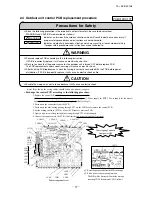
Page 99: ...dures and instructions are not adhered to WARNING Securely replace PCB according to this following instruction If PCB is incorrectly replace it will cause an electric shock or fire Be sure to check that the power source for the outdoor unit is turned OFF before replace PCB The PCB replacement under current carrying will cause an electric shock After finishing PCB replacement check that wiring is c...

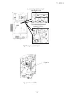
Page 100: ... 98 10 KX SM 148 Appearance of the controller PCB voltage measurement point between F1 DS1 Target PCB Fan motor voltage measurement point between L63 L64 Fig 1 Voltage measurement points ...

Page 101: ...f PCB is incorrectly replace it will cause an electric shock or fire Be sure to check that the power source for the outdoor unit is turned OFF before replace PCB The PCB replacement under current carrying will cause an electric shock After finishing PCB replacement check that wiring is correctly connected with the PCB before power distribution If PCB is incorrectly replace it will cause an electri...

Page 102: ...etallic connection binder is set in each hole of the inverter PCB of P N U V and W beforehand Then tighten the harness snubber capacitor and the power transistor with the screw together Connect snubber capacitor with P and N Installation Method to Power transistor Fig 1 Voltage Measurement Points Terminal Inverter PCB Connection binder Snubber capacitor Harness Power transistor Metallic pillar ...

Page 103: ...tch Normal SW5 5 ON Super link protocol Previos SL OFF Super link protocol New SL SW7 8 9 Function setting Switch Function SW7 Data erase data write SW8 7 segment dispalay No UP order of 1 SW9 7 segment dispalay No UP order of 10 Function of Connector Connector Function Color Connector Function Color CNEEV1 Heating EEV Red CNF2 Sub cooling coil thermistor 1 Green CNEEV2 Sub cooling coil EEV White ...

Page 104: ...㪼㫄㫇㪼㫉㪸㫋㫌㫉㪼 㪦㫌㫋㪻㫆㫆㫉㩷㫌㫅㫀㫋㩷㫋㫐㫇㪼㩷㫊㪼㫃㪼㪺㫋㫀㫆㫅 㪜㫏㫋㪼㫉㫅㪸㫃㩷㫀㫅㫇㫌㫋 㪣㪼㫍㪼㫃㪁㪆㪧㫌㫃㫊㪼 㪪㪼㪼㩷㫋㪸㪹㫃㪼㩷㪈 㪣㪼㫍㪼㫃 㪥㫆㫉㫄㪸㫃 㪢㪯㪩 㪪㪼㪼㩷㫋㪸㪹㫃㪼㩷㪊 㪥㫆㫉㫄㪸㫃 㪘㫊㩷㫇㪼㫉㩷㫍㫆㫃㫋㪸㪾㪼 㪜㫉㪸㫊㪼 㪜㫉㪸㫊㪼㪁㪆㪮㫉㫀㫋㪼 㪪㫇㪸㫉㪼 㪪㫇㪸㫉㪼 㪪㫇㪸㫉㪼 㪪㫇㪸㫉㪼 㪪㫇㪸㫉㪼 㪪㫇㪸㫉㪼 㪩㪼㫊㪼㫉㫍㪼㪻 㪩㪼㫊㪼㫉㫍㪼㪻 㪩㪼㫊㪼㫉㫍㪼㪻 㪩㪼㫊㪼㫉㫍㪼㪻 㪩㪼㫊㪼㫉㫍㪼㪻 㪢㪼㪼㫇㩷㪦㪝㪝 㪢㪼㪼㫇㩷㪦㪝㪝 㪟㪼㪸㫋㫀㫅㪾 㪥㫆㫉㫄㪸㫃 㪥㪼㫎㩷㪪㪣㩿㪘㫌㫋㫆㪀 㪢㪼㪼㫇㩷㪦㪝㪝 㪢㪼㪼㫇㩷㪦㪝㪝 㪢㪼㪼㫇㩷㪦㪝㪝 㪢㪼㪼㫇㩷㪦㪝㪝 㪢㪼㪼㫇㩷㪦㪝㪝 㪢㪼㪼㫇㩷㪦㪝㪝 㪢㪼㪼㫇㩷㪦㪝㪝 㪢㪼㪼㫇㩷㪦㪝㪝 㪢㪼㪼㫇㩷㪦㪝㪝 㪩㪼㫊㪼㫉㫍㪼㪻 㪢㪼㪼㫇㩷㪦㪝㪝 㪢㪼㪼㫇㩷㪦㪝㪝 㪢㪼㪼㫇㩷㪦㪝㪝 㪪㫇㪸㫉㪼 㪥...

Page 105: ... 103 10 KX SM 148 3 ELECTRICAL WIRING 3 1 Outdoor unit Models FDC224KXE6M 280KXE6M FDCS224KXE6M 280KXE6M PCB003Z184 ...

Page 106: ... 104 10 KX SM 148 Models FDC335KXE6M FDCS335KXE6M PCB003Z185 ...

Page 107: ... 105 10 KX SM 148 3 2 Indoor unit 1 Ceiling cassette 4 way type FDT Models All models PJF000Z191 ...

Page 108: ... 106 10 KX SM 148 2 Ceiling cassette 4 way Compact type FDTC Models All moddels A PJA003Z341 ...

Page 109: ... 107 10 KX SM 148 3 Ceiling cassette 2 way type FDTW Models FDTW28KXE6D 45KXE6D 56KXE6D PJB001Z642 ...

Page 110: ... 108 10 KX SM 148 4 Ceiling cassette 1 way compact type FDTQ a Direct blow type Models All models PJC001Z280 ...

Page 111: ... 109 10 KX SM 148 b Duct type Models All models PJC001Z281 ...

Page 112: ... 110 10 KX SM 148 5 Ceiling cassette 1 way type FDTS Model FDTS45KXE6D B PJC001Z195 ...

Page 113: ... 111 10 KX SM 148 Model FDTS71KXE6D B PJC001Z196 ...

Page 114: ... 112 10 KX SM 148 6 Duct connected High static pressure type FDU Models FDU224KXE6D 280KXE6D C PJD001Z230 ...

Page 115: ... 113 10 KX SM 148 7 Duct connected Low Middle static pressure type FDUM Models FDUM22KXE6D 28KXE6D 36KXE6D 45KXE6D 56KXE6D 71KXE6D 90KXE6D C PJR002Z258 ...

Page 116: ... 114 10 KX SM 148 Models FDUM112KXE6D 140KXE6D C PJR002Z259 ...

Page 117: ... 115 10 KX SM 148 8 Duct connected thin Low static pressure type FDUT Models All models A PJM000Z009 ...

Page 118: ... 116 10 KX SM 148 9 Duct connected Compact and Flexible type FDUH Models All models PJC001Z284 ...

Page 119: ... 117 10 KX SM 148 10 Wall mounted type FDK Models FDK22KXE6D 28KXE6D 36KXE6D 45KXE6D 56KXE6D PHA001Z029 ...

Page 120: ... 118 10 KX SM 148 Model FDK71KXE6D PHA001Z030 ...

Page 121: ... 119 10 KX SM 148 11 Ceiling suspended type FDE Models FDE36KXE6D 45KXE6D 56KXE6D C PFA003Z826 ...

Page 122: ... 120 10 KX SM 148 Models FDE71KXE6D 112KXE6D 140KXE6D C PFA003Z827 ...

Page 123: ... 121 10 KX SM 148 12 Floor standing 2 way type FDFW Models All models A PGF000Z004 ...

Page 124: ...tes 1 indicates wiring on site 2 Use twin core cable 0 75 1 25mm at signal line between indoor unit 2 and outdoor unit and signal line between indoor units 2 3 Use twin core cable 0 3mm at remote controller line See spec sheet of remote controller in case that the total length is more than 100m 4 Do not put signal line and remote controller line alongside power source line Color Marks Mark Color B...

Page 125: ...olenoid Service valve Service valve Liquid piping ø9 52 Stepping motor for electronic expansion vale Stepping motor for electronic expansion vale To next unit by turn Strainer Strainer Strainer Strainer Strainer Sub cooling coil Sub cooling coil Thermistor Outlet ThI R3 Thermistor Return air Thermistor Return air ThI A Tho SC EEVSC Tho C1 Tho D1 63H1 1 PSH SV1 Thermistor Inlet ThI R2 Thermistor Ou...

Page 126: ... piping ø25 4 Check valve Service valve Service valve Liquid piping ø12 7 Stepping motor for electronic expansion valve Stepping motor for electronic expansion valve To next unit by turn Strainer Strainer Strainer Strainer Strainer Sub cooling coil Sub cooling coil Thermistor Outlet ThI R3 Thermistor Return air ThI A Tho C1 63H1 1 PSH SV11 Thermistor Inlet ThI R2 Thermistor Outlet ThI R3 Thermisto...

Page 127: ... 125 10 KX SM 148 5 APPLICATION DATA 5 1 Installation of indoor unit PJF012D016 a ...

Page 128: ... 126 10 KX SM 148 PJF012D016 A 1 Ceiling cassette 4way type FDT ...

Page 129: ... 127 10 KX SM 148 ...

Page 130: ... 128 10 KX SM 148 ...

Page 131: ...supplied in the indoor unit Check if the gap between the ceiling plane and the indoor unit is correct by inserting the level gauge into the air outlet port of the indoor unit See below drawing Adjust the installation elevation if necessary If there is a height difference beyond the design limit between the installation level of the indoor unit and the ceiling plane the panel may be subject to exce...

Page 132: ...on displayed for two seconds shows current setting How to set the airflow direction After the setting is completed the louver which was set moves from the original position to the lower limit position and goes back to the original position again This operation is not performed if the indoor unit and or indoor unit fan is in operation Upper limit position and lower limit position are fixed and the ...

Page 133: ...e installed nearby keep them away for more than 4m Space for installation and service l When it is not possible to keep enough space between indoor unit and wall or between indoor units close the air supply port where it is not possible to keep space and confirm there is no short circuit of airflow l Install the indoor unit at a height of more than 2 5m above the floor t i n u r o o d n I t i n u ...

Page 134: ...ound 10mm from the end and fasten the screw within 5mm left to the nut l Do not apply adhesives on this end Drain socket The step part Drain hose No adhesive allowed Drain socket Metal plate 10mm Hose clamp Fasten the screw within 5 mm left to the nut Drain hose 2 Prepare a joint for connecting VP 20 pipe adhere and connect the joint to the drain hose the end made of rigid PVC and adhere and conne...

Page 135: ...der of the country and be executed according to the technical standards and other regulations applicable to electrical installation in the country Be sure to use an exclusive circuit l Use specified cord fasten the wiring to the terminal securely and hold the cord securely in order not to apply unexpected stress on the terminal l Do not put both power source line and signal line on the same route ...

Page 136: ...unit 2 The intake grille can also be attached in a rotated position by 90 degrees 1 Screw in two bolts out of the four supplied with the panel by about slightly less than 5mm mark AB Figure 1 2 Attach the hook supplied with the panel to the main body with the hook fixing screw 1 screw Figure 2 3 Open the intake grille 4 Please remove the screw of a corner panel and remove a corner panel four place...

Page 137: ...2 3 L L Caution Caution Lower position Movable range Upper position Louver No Piping side Drain hose side Control box downwards horizontal the position of the louver EXAMPLE Press or button selection of louver No Select the louver No to be set according to the right figure 4 Press button Louver adjusting mode ends and returns to the original display 10 EXAMPLE Press or button selection of upper li...

Page 138: ... height can be adjusted finely Refer to the installation manual for decorative panel for details Indoor unit Hose Center of box Drain hose piece Accessory Installed on site panel Control 97 446 90 97 640 40 Suspension bolts pitch Ceiling hole size Suspension bolts pitch Ceiling hole size Hanger plate for E F 5 Ø4 Holes for tapping screws Hole suspension bolt 95 64 278 264 310 D B A 230 310 364 405...

Page 139: ... tapes to wrap and make joint part gapless Drain up The position for drain pipe outlet can be raised up to 750mm above the ceiling Use elbows for installation to avoid obstacles inside ceiling If the horizontal drain pipe is too long before vertical pipe the backflow of water will increase when the unit is stopped and it may cause overflow of water from the drain pan on the indoor unit In order to...

Page 140: ...ubber plug Remove General hard type PV pipe VP 20 Transparent soft tube option Connector for drain motor CNR blue 2P Remove Insulation Attach the panel on the indoor unit after electrical wiring work Work procedure 1 Using the paper pattern attached as an accessory check to ensure the unit height and ceiling opening are finished true to the specified dimensions Remove the suction panel from the pa...

Page 141: ... 139 10 KX SM 148 4 Ceiling cassette 1way compact type FDTQ PJC012D121 ...

Page 142: ... 140 10 KX SM 148 ...

Page 143: ... 141 10 KX SM 148 ...

Page 144: ...inlet Air outlet Wide Panel 780 Suction inlet 650 Air outlet For tapping PJC012D118 PANEL INSTALLATION MANUAL Confirm the mounting level of air conditioner and ceiling Adjust the level of air conditioner so that the bottom of air conditioner is at the same level as that of ceiling plate the T bar The level differential tolerance between the bottom surface of ceiling and that of main unit is that a...

Page 145: ...for louver motor white 4P and the connector for limit switch white 3P The connector on the indoor unit side is in the control box After connecting the connectors pass the wiring on the panel side through wiring hole Hold the connector in the control box Close control box cover and tighten 2 screws Mount the chain attached with suction grille on the panel using screw The screws for mounting chain a...

Page 146: ... 144 10 KX SM 148 2 Parts Models QR PNA 14W ER QR PNB 14W ER PJC012D102 h ...

Page 147: ... 145 10 KX SM 148 0 10 20 30 6 7 8 9 10 External static pressure Pa Air flow m3 min L o w M e d iu m H i g h P H i g h U p p e r l i m i t ...

Page 148: ... 146 10 KX SM 148 ...

Page 149: ... 147 10 KX SM 148 5 Ceiling cassette 1way type FDTS PJC012D016 ...

Page 150: ... 148 10 KX SM 148 ...

Page 151: ... 149 10 KX SM 148 ...

Page 152: ... 150 10 KX SM 148 6 Duct connected High static pressure type FDU PJD012D053 ...

Page 153: ... 151 10 KX SM 148 ...

Page 154: ... 152 10 KX SM 148 ...

Page 155: ...FUT PG TVTQFOTJPO CPMU OVU BOE TQSJOH XBTIFS PO TJUF 4VTQFOTJPO PMU PDBUJPO VDU 8PSL 12D319 VMUJ UZQF 4JOHMF UZQF _ 6 5 NN _ VMUJ UZQF 4JOHMF UZQF _ _ VMUJ UZQF 4JOHMF UZQF 4QPU OVNCFST TQPU TQPUT PS TQPUT _ PS TQPUT DPSSVHBUFE CPBSE GPS QSFWFOUJOH TQVUUFSJOH JT BUUBDIFE UP UIF NBJO CPEZ PG UIF BJS DPOEJUJPOFS PO UIF PVUMFU QPSU P OPU SFNPWF JU VOUJM DPOOFDUJOH UIF EVDU O BJS mMUFS DBO CF QSPWJEFE...

Page 156: ...entio pipe as clo Do not set When sharin one unit la below the addition se main drain p Duct Work continued When placing the inlet port to carry out suction from the bottom side use the following procedure to replace the suction duct joint and the bottom plate Remove the screws which fasten the Replace the removed bottom plate bottom plate and the duct joint on the and duct joint inlet port side o...

Page 157: ... setting is done air outlet speed from indoor unit will increase and waterdrop may be blown out and wet the ceiling or the furniture insulation P20 joint Prepare on site VP20 Prepare on site Pipe cover small For insulation Prepare on site esion Insert water supply hose for 20mm 30mm to supply water Insert hose facing toward bottom Attached drain hose clamp Drain piping Main unit Drain situation ca...

Page 158: ... 156 10 KX SM 148 8 Duct connected thin Low static pressure type FDUT PJM012D032 B ...

Page 159: ... 157 10 KX SM 148 ...

Page 160: ... 158 10 KX SM 148 ...

Page 161: ... 159 10 KX SM 148 9 Duct connected Compact and Flexible type FDUH PJC012D207 a ...

Page 162: ... 160 10 KX SM 148 0 10 20 30 5 6 7 8 9 External static pressure Pa Air flow m3 min Hi gh P Hi gh Lo w Me diu m U p p e r li m it ...

Page 163: ... 161 10 KX SM 148 ...

Page 164: ... 162 10 KX SM 148 PHA012D039 10 Wall mounted type FDK ...

Page 165: ... 163 10 KX SM 148 ...

Page 166: ... 164 10 KX SM 148 ...

Page 167: ...JHIUJOH EFWJDF TPNFUJNFT BGGFDUT UIF JOGSBSFE SFDFJWFS GPS UIF XJSFMFTT SFNPUF DPOUSPMMFS BOE UIF BJS DPOEJUJPOFS NJHIU OPU XPSL QSPQFSMZ 2 IFDL JG UIF QMBDF XIFSF UIF BJS DPOEJUJPOFS JT JOTUBMMFE DBO IPME UIF XFJHIU PG UIF VOJU G JU JT OPU BCMF UP IPME SFJOGPSDF UIF TUSVDUVSF XJUI CPBSET BOE CFBNT TUSPOH FOPVHI UP IPME JU G UIF TUSFOHUI JT OPU FOPVHI JU DPVME DBVTF JOKVSZ EVF UP VOJU GBMMJOH 3 G ...

Page 168: ...JUI BOPUIFS TQBOOFS JO PSEFS UP BWPJE VOFYQFDUFE TUSFTT UP UIF DPQQFS QJQF BOE UIFO SFNPWF UIFN 8IFO GBTUFOJOH UIF áBSF OVU BMJHO UIF SFGSJHFSBUJPO QJQF XJUI UIF DFOUFS PG áBSF OVU TDSFX UIF OVU GPS UJNFT CZ IBOE BOE UIFO UJHIUFO JU CZ TQBOOFS XJUI UIF TQFDJàFE UPSRVF NFOUJPOFE JO UIF UBCMF CFMPX BLF TVSF UP IPME UIF QJQF PO UIF JOEPPS VOJU TFDVSFMZ CZ B TQBOOFS XIFO UJHIUFOJOH UIF OVU JO PSEFS UP...

Page 169: ...MJNJU QPTJUJPO 4FMFDU UIF VQQFS MJNJU PG MPVWFS NPWBCMF SBOHF iQPTJUJPO u JT UIF NPTU IPSJ POUBM BOE iQPTJUJPO u JT UIF NPTU EPXOXBSE iQPTJUJPO u JT UP SFUVSO UP UIF GBDUPSZ TFUUJOH G ZPV OFFE UP DIBOHF UIF TFUUJOH UP UIF EFGBVMU TFUUJOH VTF iQPTJUJPO u 1SFTT 4 5 CVUUPO JYJOH PG UIF VQQFS MJNJU QPTJUJPO 5IF VQQFS MJNJU QPTJUJPO JT àYFE BOE UIF TFUUJOH QPTJUJPO JT EJTQMBZFE GPS UXP TFDPOET 5IFO QSP...

Page 170: ... 168 10 KX SM 148 PGF012D004 12 Floor standing 2 way type FDFW ...

Page 171: ... 169 10 KX SM 148 ...

Page 172: ...This function is not able to be set with wireless remote controls or simple remote control RCH H3 2 For setting the swing range of other louvers return to 1 and proceed same procedure respectively 10 KX SM 148 1 2 ...

Page 173: ... 171 10 KX SM 148 13 Outdoor air processing unit type FDU F PJD012D059 ...

Page 174: ... 172 10 KX SM 148 ...

Page 175: ... 173 10 KX SM 148 ...

Page 176: ... circuit Power source with insufficient capacity and improper work can cause electric shock and fire Use specified wire for electrical wiring fasten the wiring to the terminal securely and hold the cable securely in order not to apply unexpected stress on the terminal Loose connections or hold could result in abnormal heat generation or fire Arrange the electrical wires in the control box properly...

Page 177: ...a cooling test run Pressing the button the TEMP button or MODE button will end a cooling test run Cooling test run will end after 30 minutes pass shown on the screen will go off A 2D922 Remote ontroller line Earth line 3mm2 2cores 2 0mm2 3mm2 2cores 2 0mm2 ne cord e 2 0 3 5mm2 0 75 1 25mm2 0 3 2 0mm2 Operation data can be checked with remote control unit operation 1 Press the button The display ch...

Page 178: ... button End Press button It is possible to finish above setting on the way and unfinished change of setting is unavailable Record and keep the setting Note 1 The initial setting marked is decided by connected indoor and outdoor unit and is automatically defined as following table Function No Remote controller function02 Remote controller function06 Remote controller function07 Remote controller func...

Page 179: ...rol and keep the set temperature If you change the remote controller function 14 you must change the indoor function 04 accordingly You can select the louver stop position in the four The louver can stop at any position In normal working indication indoor unit temperature is indicated instead of airflow Only the master remote controller can be indicated Heating preparation indication should not be...

Page 180: ...ng 2 0 C increase in return air temperature of indoor unit When heating thermostat is OFF fan speed is low speed When heating thermostat is OFF fan speed is set speed When heating thermostat is OFF fan speed is operated intermittently When heating thermostat is OFF the fan is stopped When the remote thermistor is working FAN OFF is set automatically Do not set FAN OFF when the indoor unit s thermi...

Page 181: ... nipper or knife and grind burrs with a file etc Install the lower case to the flat wall with attached two wooden screws Connect the remote controller co terminal block Connect the terminal of remote c with the terminal of indoor unit X X and Y are no polarity Wiring route is as shown in the rig depending on the pulling out dire The wiring inside the remote cont The sheath should be peeled off The...

Page 182: ...onnect the remote controller cord to the terminal block Connect the terminal of remote controller X Y with the terminal of indoor unit X Y X and Y are no polarity Wiring route is as shown in the right diagram depending on the pulling out direction The wiring inside the remote controller case should be within 0 3mm2 recommended to 0 5mm2 The sheath should be peeled off inside the remote controller ...

Page 183: ...er three seconds The indication changes to FUNCTION SET 2 Press button once and change to the TEMP RANGE indication 3 Press SET button and enter the temperature range setting mode 4 Select UPPER LIMIT or LOWER LIMIT by using button 5 Press SET button to fix 6 When UPPER LIMIT is selected valid during heating Press SET button to fix Indication example UPPER 26 C Displayed for two seconds After the ...

Page 184: ... 10 KX SM 148 182 ...

Page 185: ...econds and the FUNCTION SET will be displayed Press SET button Selecct FUNCTION remote controller function or I U FUNCTION indoor unit function Operation message Function description setting description Function No Fixing button Finishing button 7 2 1 6 Starting button Previous screen button Indoor unit selection button Press SET button 6 DATA LOADING Indication with blinking Display is changed to...

Page 186: ...lve and disconnecting refrigerant pipes in case of pump down operation If disconnecting refrigerant pipes in state of opening service valves before compressor stopping you may incur frost bite or injury from an abrupt refrigerant outflow and air can be sucked which can cause burst or personal injury due to anomalously high pressure in the refrigerant circuit Ensure that no air enters in the refrig...

Page 187: ...ng indoor unit if connected into the system will impair proper system operation Items sold separately Refrigerant pipe distribution parts which are not contained in the package will be required for installation As for refrigerant pipe distribution parts we offer branching pipe sets Model type DIS and header sets Model type HEAD as parts used on the indoor side of piping Please select one suiting y...

Page 188: ...nt capacity to withstand pressure make sure to use pipes of 1 2H material and thickness larger than the minimum thickness When a pipe is branched make sure to use our branching set or header set When setting branching pipes take care of the mounting direction and consult carefully with the instruction manual Regarding the handling of operation valve refer to 4 3 1 Operating method of operation val...

Page 189: ... ø15 88 t1 0 ø19 05 t1 0 1 ø19 05 t1 0 Liquid pipe ø 9 52 t0 8 ø12 7 t0 8 ø15 88 t1 0 For ø19 05 or larger use C1220T 1 2H material Total capacity at downstream Less than 180 180 371 371 540 Branch pipe set DIS 22 1 DIS 180 1 DIS 371 1 c Between branching at indoor unit side indoor unit side Section C in Fig 1 According to the table of pipe size for indoor unit However it should never exceed the s...

Page 190: ...WF N PS B MPOHFS EJTUBODF CFUXFFO BO PVUEPPS VOJU BOE BO BODIPSJOH QPJOU XIFSF UIF QJQJOH JT TFDVSFE BT JMMVTUSBUFE CFMPX GBJMVSF UP PCTFSWF UIJT JOTUSVDUJPO NBZ SFTVMU JO B QJQF GSBDUVSF EFQFOEJOH PO B NFUIPE PG JTPMBUJOH WJCSBUJPOT FNQMPZFE 5IF QJQF TIPVME CF BODIPSFE FWFSZ N PS MFTT UP JTPMBUF UIF WJCSBUJPO H MBSF OVU QBSBMMFM TJEF NFBTVSFNFOU NN φ φ φ φ PQQFS QJQF PVUFS EJBNFUFS H A B MBSFE QJ...

Page 191: ...FS B OJUSPHFO HBT nPX 8JUIPVU OJUSPHFO HBT B MBSHF RVBOUJUZ PG GPSFJHO NBUUFST PYJEJ FE mMN BSF DSFBUFE DBVTJOH B DSJUJDBM GBJMVSF GSPN DBQJMMBSZ UVCF PS FYQBOTJPO WBMWF DMPHHJOH JWF TVGmDJFOU QSPUFDUJPOT DPNQSFTTFE BOE CSB FE PS XJUI BO BEIFTJWF UBQF TP UIBU XBUFS PS GPSFJHO NBUUFST NBZ OPU FOUFS UIF QJQJOH 1FSGPSN nVTIJOH 5P nVTI UIF QJQJOH DIBSHF OJUSPHFO HBT BU BCPVU 1B XJUI B QJQF FOE DMPTFE ...

Page 192: ...JDF QBOFM FBU JOTVMBUJPO BOE NPJTUVSF DPOEFOTBUJPO QSPPG 3FGSJHFSBOU QJQF TJ F EEJUJPOBM DIBSHF RVBOUJUZ LH N 3FNBSL 1 8J MFD SBJOBHF 0V 0 G SBJO FMCPX QD SBJO HSPNNFU QDT PNNFSDJBM HFOFSBM QVSQPTF IBSE QPMZDBSCPOBUF QJQF 71 8IFSF XBUFS ESBJOFE GSPN UIF PVUEPPS VOJU NBZ GSFF F DPOOFDU UIF ESBJO QJQF VTJOH PQUJPOBM ESBJO FMCPX BOE ESBJO HSPNNFU 0VUEPPS VOJU IBT ESBJO PVUMFUT PO UIF CPUUPN 8IFO HVJE...

Page 193: ...BO DBVTF BO BCOPSNBM PWFSIFBU BDDJEFOU H PS QPXFS TVQQMZ DBCMFT VTF DPOEVJUT I 1MFBTF EP OPU MBZ FMFDUSPOJD DPOUSPM DBCMFT SFNPUF DPOUSPM BOE TJHOBMJOH MJOFT BOE PUIFS IJHI DVSSFOU DBCMFT UPHFUIFS PVUTJEF UIF VOJU BZJOH UIFN UPHFUIFS DBO SFTVMU JO NBMGVODUJPOJOH PS B GBJMVSF PG UIF VOJU EVF UP FMFDUSJD OPJTFT J 1PXFS DBCMFT BOE TJHOBMJOH MJOFT NVTU BMXBZT CF DPOOFDUFE UP UIF UFSNJOBM CMPDL BOE TFD...

Page 194: ...7 PS 7 FGPSF UVSOJOH UIF QPXFS PO DIFDL UIF SFTJTUBODF PO UIF TJHOBM DBCMF UFSNJOBM CMPDL G JU JT MFTT UIBO û QPXFS TVQQMZ DBCMFT NBZ CF DPOOFDUFE UP UIF TJHOBM DBCMF UFSNJOBM CMPDL 4UBOEBSE SFTJTUBODF WBMVF VNCFS PG 9 4FSJFT VOJUT DPOOFDUFE VNCFS PG 9 4FSJFT VOJUT DPOOFDUFE Y G UIF SFTJTUBODF WBMVF JT MFTT UIBO û EJTDPOOFDU UIF TJHOBM DBCMFT UFNQPSBSJMZ UP EJWJEF UP NPSF UIBO POF OFUXPSL UP SFEVD...

Page 195: ...PQFS BEESFTT TFUUJOH BTF O BTF BVUPNBUJD BEESFTT TFUUJOH JT OPU BWBJMBCMF 4FU BEESFTTFT NBOVBMMZ A1 B1 A2 B2 A B A B A B A B A B A B A1 B1 A2 B2 A1 B1 A2 B2 A1 B1 A2 B2 A B A B A B A B A B A B A1 B1 A2 B2 A1 B1 A2 B2 A1 B1 A2 B2 A B A B A B A B A B A B A1 B1 A2 B2 A1 B1 A2 B2 A1 B1 A2 B2 A B A B A B A B A B A B A1 B1 A2 B2 A1 B1 A2 B2 4VNNBSZ PG BEESFTT TFUUJOH NFUIPET mHVSFT JO TIPVME CF VTFE XJU...

Page 196: ... JOEPPS VOJU BEESFTTFT BSF BMM TFU UIF TFHNFOU EJTQMBZ QBOFM JOEJDBUJPO XJMM TXJUDI UP i 6 w BOE TUBSU nJDLFSJOH G BO FSSPS JT EFUFDUFE JO UIJT QSPDFTT UIF EJTQMBZ XJMM TIPX i w IFDL UIF TFHNFOU EJTQMBZ QBOFM PG FBDI PVUEPPS VOJU FQFOEJOH PO UIF OVNCFS PG DPOOFDUFE JOEPPS VOJUT JU NBZ UBLF BCPVU NJOVUFT CFGPSF UIF JOEPPS VOJU BEESFTTFT BSF BMM TFU 45 1 FUXPSL EFmOJUJPO TFUUJOH FUXPSL DPOOFDUJPO 8I...

Page 197: ...FE 8IFO BEESFTTFT BSF TFU CF TVSF UP QFSGPSN B UFTU SVO BOE FOTVSF UIBU ZPV DBO PQFSBUF BMM JOEPPS BOE PVUEPPS VOJUT OPSNBMMZ MTP DIFDL UIF BEESFTTFT BTTJHOFE UP UIF JOEPPS VOJUT 0 0 JOEPPS PVUEPPS GBDUPSZ TFUUJOH Y JTDPOOFDU FBDI PVUEPPS VOJU 45 1 45 1 45 1 45 1 OEPPS VOJU OEPPS VOJU OEPPS VOJU OEPPS VOJU OEPPS VOJU OEPPS VOJU OEPPS VOJU OEPPS VOJU OEPPS VOJU OEPPS VOJU OEPPS VOJU OEPPS VOJU OEPP...

Page 198: ... ZPV IBWF GJOJTIFE DIBOHJOH BEESFTTFT QSFTT UIF 4FU TXJUDI XIJMF i w JT TIPXO 8IJMF OFX TFUUJOHT BSF CFJOH USBOTNJUUFE i4 5 0 1 5 w XJMM CF JOEJDBUFE 5IFO UIF SFNPUF DPOUSPMMFS EJTQMBZ XJMM DIBOHF UP UIF OPSNBM TUBUF G ZPV XBOU UP FOE UIF TFTTJPO XJUIPVU SFGMFDUJOH OFX BEESFTT TFUUJOHT FGPSF ZPV DPNQMFUF UIF QSFTFOU BEESFTT TFUUJOH TFTTJPO QSFTT UIF i0 0 w TXJUDI 5IFO UIF EJTQMBZ JT DIBOHF UP FYJU...

Page 199: ...FX 4 PEF POUFOUT PG B EJTQMBZ 1MFBTF DIFDL POUFOUT PG B EJTQMBZ BVTF PEF VQMJDBUJOH JOEPPS VOJU BEESFTT ODPSSFDU QBJSJOH PG JOEPPS PVUEPPS VOJUT ODPSSFDU BEEFSFTT TFUUJOH PG JOEPPS VOJUT EESFTT TFUUJOH GPS QMVSBM SFNPUF DPOUSPMMFST ODPSSFDU TFUUJOH VQMJDBUJOH PVUEPPS VOJU BEESFTT ODPSSFDU NBOVBM BEESFTT TFUUJOH OEPPS VOJU BEESFTT JT TFU GSPN QMVSBM SFNPUF DPOUSPMMFST 1MVSBM PVUEPPS VOJUT BSF FYJTU...

Page 200: ...VTF O4 GPS UIF JOQVU PG GPSDFE DPPMJOH NPEF TFU 1 BU BOE 48 BU 0 5P VTF O4 GPS UIF JOQVU PG GPSDFE DPPMJOH NPEF TFU 1 BU BOE 48 BU 0 O UIF FOFSHZ TBWJOH NPEF UIF DBQBDJUZ SFTUSJDUJPO CFDPNFT FGGFDUJWF FWFO JG OP TJHOBMT BSF JOQVU BU FYUFSOBM JOQVU UFSNJOBMT 7BMJE JOWBMJE JT DIBOHFE EFQFOEJOH PO PVUEPPS UFNQFSBUVSF U JT BMXBZT 7BMJE SFHBSEMFTT PG PVUEPPS UFNQFSBUVSF 48 TFUUJOH PO 1 48 MPTFE BDUPSZ ...

Page 201: ... UIFJS PSJHJOBM TUBUF BOE XJSJOH SPVUF BOE UIF OFDFTTBSZ DMFBSBODF GSPN BMM NFUBM QBSUT TIPVME CF TFDVSFE FUIPE PG TUBSUJOH B UFTU SVO GPS B DPPMJOH PQFSBUJPO GSPN BO PVUEPPS VOJU QMFBTF PQFSBUF B SFNPUF DPOUSPM VOJU BDDPSEJOH UP UIF GPMMPXJOH TUFQT B 4UBSU PG B DPPMJOH UFTU SVO 0QFSBUF UIF VOJU CZ QSFTTJOH UIF 45 35 4501 CVUUPO 4FMFDU UIF i 00 w NPEF XJUI UIF 0 CVUUPO 1SFTT UIF 5 45 36 CVUUPO GPS...

Page 202: ...e supplying nitrogen gas About brazing Name Accessory pipe Heat insulating material Band Straight pipe 1 Straight pipe 2 Elbow ADownward BForward CRightward DBackward No 1 2 3 4 5 6 Quantity 1 1 2 1 1 or 0 1 or 0 Remark Accessory Accessory Accessory Procured at the field Procuredatthefield Notrequiredfordownwarddirection Procuredatthefield Notrequiredfordownwarddirection Straight pipe1 Straight pi...

Page 203: ...played on the 7 segment display of master outdoor unit If the unit has been operating before check operation wait for 5 minutes after stopping the unit operation before starting check operation in order to avoid misjudgment In combination use judging operation valves opened or closed by check operation can be done as no good NG when all of operation valves in liquid line gas line and oil equalizin...

Page 204: ...k method refer to 3 Confirmation before check operation 2 For details of check operation refer to 4 Check operation procedure 3 For measures to be taken in case of NG refer to 5 Measures to be taken after check operation Preliminary check Note 1 Judgment of checked result Note 3 End NG OK Auto checking Note 2 Start ...

Page 205: ...ethod is of new SL Check the model name of outdoor unit indoor units central control device etc System is not in error stop condition Check to see if any error code E is displayed on indoor or outdoor unit 6 Outdoor unit operation valve Outdoor unit operation valve is opened 1 Check visually 7 Refrigerant amount Proper amount of refrigerant is charged Check the additional charged amount of refrige...

Page 206: ...is judged normal End the check operation CHL Operation valve may be closed Refer to 5 Measures to be taken after check operation CHU Anomalous indoor unit No Refrigerant piping or signal wiring between indoor and outdoor units may not be connected correctly CHJ Anomalous indoor unit No Indoor expansion valve may not be operating properly CHE Check operation has not ended properly All judgment resu...

Page 207: ...r may be anomalous or disconnected 2 See page 207 Operation valve on outdoor unit may be left closed Check it especially when many indoor units No are displayed in data display column of CHU it may be displayed by influence of liquid flooding due to the trouble on any other indoor unit If CHJ is displayed at the same time check preferentially the indoor unit displaying CHJ and after repairing perf...

Page 208: ...in place Refer to the technical manual or the above It might have been started operation while bottom of compressor was still cold Perform check operation again after the bottom of compressor has been enough warm E 49 Low pressure anomaly Refrigerant circuit may be choked at a certain place Refer to the technical manual or the above E 36 3 Liquid flooding anomaly It may be in the same condition as...

Page 209: ... unit 3 Indoor unit 4 2 If the connector comes off by a weak pull it s no good If not come off It s OK The connector of indoor heat exchanger temperature thermistor Normal Disconnected 3 If the connector comes off by a weak pull it s no good If not come off It s OK The connector of indoor expansion valve coil Normal Disconnected 4 The indoor expansion valve coil itself Normal Disconnected from mai...

Page 210: ... 57 FD 18 FD 58 FD 19 FD 59 FD 20 FD 60 FD 21 FD 61 FD 22 FD 62 FD 23 FD 63 FD 24 FD 64 FD 25 FD 65 FD 26 FD 66 FD 27 FD 67 FD 28 FD 68 FD 29 FD 69 FD 30 FD 70 FD 31 FD 71 FD 32 FD 72 FD 33 FD 73 FD 34 FD 74 FD 35 FD 75 FD 36 FD 76 FD 37 FD 77 FD 38 FD 78 FD 39 FD 79 FD 40 FD 80 FD Date of installation d m y Name of installer Superlink version Superlink II Superlink I In case of Superlink I the ch...

Page 211: ...structions for installing the branch pipe set option 2 I D φ25 4 O D φ28 58 100 P 9 I D φ34 92 O D φ38 1 100 P 15 I D φ25 4 O D φ28 58 100 P 9 I D φ34 92 O D φ38 1 100 P 15 DIS 540 2 ID Ǿ25 4 OD Ǿ28 58 100 100 P 9 ID Ǿ34 92 OD Ǿ38 1 P 15 ...

Page 212: ... 210 10 KX SM 148 2 model type DIS model type HEAD ...

Page 213: ... 211 10 KX SM 148 2 2 ...

Page 214: ... 212 10 KX SM 148 2 2 2 2 2 ...

Page 215: ... periods protect the unit with covering Production by order Model No FDCS224KXE6M FDCS280KXE6M FDCS335KXE6M Nominal Cooling Capacity 22 4kW 28 0kW 33 5kW Additional treatment from the standard series Fin pipe Side plate Description undercoat Cation electrodeposition coating topcoat polyester powder coating or acrylic baked coating undercoat Cation electrodeposition coating topcoat polyester powder...

Page 216: ...rigeration Systems Headquarters 16 5 2 chome Kounan Minato ku Tokyo 108 8215 Japan Fax 03 6716 5926 Because of our policy of continuous improvement we reserve the right to make changes in all specifications without notice Copyright MITSUBISHI HEAVY INDUSTRIES LTD c ...

Reviews: