-
-
'11•SAF-T-161
Ԝ
Trial operation (continued)
When indoor unit address number is displayed on
remote controller, pushing the (MODE)
button to make the indoor unit with that number
blow air (Display example:" ").
Push the (MODE) button again to stop the
operation.
However, this operation is invalid on the
air-conditioning running.
After a unit is energized, it is possible
to display an indoor unit address by
pressing button on
the remote control unit.
Press the or button to make
sure that all indoor units connected
are displayed in order.
㿟㩷 㿠㩷
㩷
㿟㩷 㿠㩷
㿟㩷 㿠㩷
㩷
㿈 㿉
㩷
㩷
㩷
㿈 㿉
㿟 㿠
㩷
㩷
㿈㩷 㿉㩷
㩷
㿈 㿉
㿟 㿠
㩷
㩷
㩷
㿈 㿉
㿟 㿠
㩷
㩷
㩷
㿈 㿉
㿟 㿠
㩷
㩷
㩷
㿈 㿉
㿟 㿠
㩷
㩷
㩷
㿈 㿉
㿟 㿠
㩷
㩷
㿟 㿠
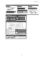
Installation and wiring of remote controller
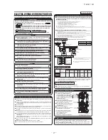
Control plural indoor units by a single remote controller
Ԙ
A remote controller can control plural indoor units (up to 16)
In above setting, all plural indoor units will operate under same mode and temperature setting.
ԙ
Connect all indoor units with 2 core remote controller line for group control.
Ԛ
Use the function of manual address setting to set the indoor and outdoor address number.
٤
Do not forget to set the number for the outdoor units.
ԛ
As shown in the following figure, the remote control can be used to control multiple outdoor units.
Ԝ
One remote control is able to perform group control for multiple units (maximum 16 units).
٤
Use the rotary SW1 and SW2 provided on the indoor unit PCB (Printed circuit board) to set unique remote control
communication address avoiding duplication.
Outdoor unit
No.01
Outdoor unit
No.02
Indoor unit
Indoor unit
Outdoor No.01
Indoor No.01
Indoor unit
Indoor unit
Indoor unit
Indoor unit
Action time
Indoor unit
Action time
SW1” Master”
Action time
SW1” Slave”
Switch Setting Contents
Master
Slave
Slave remote
controller
Wired remote controller: SW1
Wireless kit: SW1-2
Master remote
controller
AIR CON NO
Confirming method of indoor units
Master/slave setting when more than one remote control unit are used
A maximum of two remote control units can be connected to one indoor unit (or one group of indoor units.)
Latest "function setting" is superior than previous one.
Acceptable combination is "two (2) wired remote controllers", "one (1) wired remote controller and one (1)
wireless kit" or "two (2) wireless kits".
Set SW1 to "Slave" for the slave remote control unit. It was factory set to "Master" for shipment.
Note:The setting "Remote control unit sensor enabled" is only selectable with the master remote control unit
in the position where you want to check room temperature.
Checking operation data
Outdoor No.02
Indoor No.04
Outdoor No.01
Indoor No.02
Outdoor No.02
Indoor No.05
Outdoor No.01
Indoor No.03
Outdoor No.02
Indoor No.06
٨
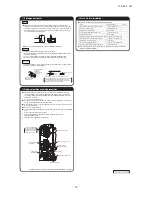
Do not install it on the following places.
(1) Place exposed to direct sunlight
(4) Hot surface or cold surface enough to generate condensation
(2) Places near heat devices
(5) Place exposed to oil mist or steam directly.
(3) High humidity places
(6) Uneven surface
ԛ
Remote Control, Wiring and functions
Ԙ
Install remote controller referring to the attached manual.
ԙ
Wiring of remote controller should use 0.3mm
2
x2 core wires or cables.
The insulation thickness is 1mm or more. (on-site configuration)
Ԛ
Maximum prolongation of remote control wiring is 600 m.
If the prolongation is over 100m, change to the size below.
But, wiring in the remote controller case should be under 0.5mm
2
. Change the wire size outside of the case according to
wire connecting. Waterproof treatment is necessary at the wire connecting section. Be careful about contact failure.
100-200m ...................0.5mm
2
×2 core
Under 400m.....................1.25mm
2
× 2 core
Under 300m................0.75mm
2
× 2 core
Under 500m.....................2.0mm
2
× 2 core
ԛ
Avoid using multi-core cables to prevent malfunction.
Ԝ
Keep remote controller line away from earth (frame or any metal of building).
ԝ
Make sure to connect remote controller line to the remote controller and terminal block of indoor unit. (No polarity)
Ԝ
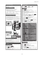
Trial operation
The method of trial cooling operation
Remote controller line
(No polarity)
Remote controller line
(No polarity)
Operate the remote control unit as follows.
1. Starting a cooling test run.
Ԙ
Start the system by pressing the button.
ԙ
Select “ (Cool)” with the (MODE) button.
Ԛ
Press the
TEST
button for 3 seconds or longer.
The screen display will switch to: “
”
ԛ
When the (SET) button is pressed while “
” is indicated, a cooling test
run will start.
The screen display will switch to “ ”.
2. Ending a cooling test run.
Pressing the button, the (TEMP) button or (MODE) button will end a
cooling test run. (Cooling test run will end after 30 minutes pass.)
“ ” shown on the screen will go off.
Operation data can be checked with remote control unit operation.
1. Press the button.
The display change “ ”
2. Press the (SET) button while “ ” is displayed.
When only one indoor unit is connected to remote controller, “ ” is displayed
(blinking indication during data loading).
Next, operation data of the indoor unit will be displayed. Skip to step 7.
4. When plural indoor units is connected, the smallest address number of indoor unit among all
connected indoor unit is displayed.
[Example]:
“ ” (blinking 1 seconds) “ ” blinking.
5. Select the indoor unit number you would like to have data displayed with the button.
6. Determine the indoor unit number with the (SET) button.
(The indoor unit number changes from blinking indication to continuous indication)
“ ” (The address of selected indoor unit is blinking for 2 seconds.)
“ ” (A blinking indication appears while data loaded.)
Next, the operation data of the indoor unit is indicated.
7. Upon operation of the button, the current operation data is displayed in order from
data number 01.
The items displayed are in the following table
̪
Depending on models, the items that do not have corresponding data are not displayed.
8. To display the data of a different indoor unit, press the button, which allows you to
go back to the indoor unit selection screen.
9. Pressing the button will stop displaying data.
Pressing the (RESET) button during remote control unit operation will undo your last
operation and allow you to go back to the previous screen.
٧
If two (2) remote controllers are connected to one (1) inside unit, only the master controller is available
for trial operation and confirmation of operation data. (The slave remote controller is not available.)
Drain pump operation from remote control unit is possible. Operate a remote control unit by
following the steps described below.
1. To start a forced drain pump operation.
Ԙ
Press the TEST button for three seconds or longer.
The display will change “ ”
ԙ
Press the button once and cause “ ” to be displayed.
Ԛ
When the (SET) button is pressed, a drain pump operation will start.
Display: “ ”
2. To cancel a drain pump operation.
Ԙ
If either (SET) or button is pressed, a forced drain pump operation will
stop. The air conditioning system will become OFF.
٧
If two (2) remote controllers are connected to one (1) inside unit, only the master controller is available
for trial operation and confirmation of operation data. (The slave remote controller is not available.)
Trail operation of drain pump
̪
Depending on outdoor unit model, there are data not shown.
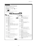
Number
01
02
03
04
05
06
07
08
09
10
11
12
21
22
23
24
25
26
27
28
29
30
31
32
33
34
35
36
37
38
39
Data Item
(Operation Mode)
(Set Temperature)
(Return Air Temperature)
(Remote Controller Thermistor Temperature)
(Indoor Unit Heat Exchanger Thermistor / U Bend)
(Indoor Unit Heat Exchanger Thermistor /Capillary)
(Indoor Unit Heat Exchanger Thermistor /Gas Header)
(Indoor Unit Fan Speed)
(Frequency Requirements)
(Response Frequency)
(Pulse of Indoor Unit Expansion Valve)
(Total Running Hours of The Indoor Unit)
(Outdoor Air Temperature)
(Outdoor Unit Heat Exchanger Thermistor)
(Outdoor Unit Heat Exchanger Thermistor)
(Compressor Frequency)
(High Pressure)
(Low Pressure)
(Discharge Pipe Temperature)
(Comp Bottom Temperature)
(Current)
(Target Super Heat)
(Super Heat)
(Discharge Pipe Super Heat)
(Protection State No. of The Compressor)
(Outdoor Unit Fan Speed)
(63H1 On/Off)
(Defrost Control On/Off)
(Total Running Hours of The Compressor)
(Pulse of The Outdoor Unit Expansion Valve EEVC)
(Pulse of The Outdoor Unit Expansion Valve EEVH)


