-
0
-
'11•SAF-T-161
ԝ
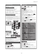
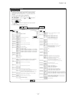
Function Setting by Remote Controller
Pressure control selection
During cooling
During heating
Remote control function
Auto cleaning
Display
Valid/
�
Invalid
Temperature correction
Remark
Used to correct outlet temperature during cooling.
Outlet temperature during cooling is
corrected
Outlet temperature during heating is
corrected
Minus/
�
Plus
Heating room
temperature
correction
�
No correction
/+1.0/+2.0
/+3.0 °C
-2.0/-1.5/-1.0
�
No correction
/+1.0/+1.5/+2.0 °C
-4.0/-3.0/-2.0
�
No correction
/+2.0/+3.0/+4.0 °C
�
No correction
/+1.0/+2.0
/+3.0 °C
Suction
temperature
correction
Standard control
15°C
36°C
External adjuster control
25°C
24°C
Outlet temperature control
•Outlet temperature control is effective when SW7-3 is set to ON.
•Outlet temperature setting values are as listed below depending on the pressure
control selection
•Outlet temperature can be changed by the remote control functions “01: Auto cleaning”,
“08: Heating room temperature correction” and “09: Suction temperature correction”.
Note. Remote controller RC-D4 has no auto cleaning selection. (No display)
This means that there is no minus correction.
�
Default setting
Note 2
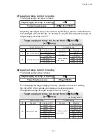
Auto operation control
•If the remote control operation switch is set to the “Auto”, the “Cooling”,
Blower” and “Heating” are selected automatically.
•Selecting temperature is changed with the remote control function setting –
11: Ventilation setting.
Ventilation setting
No ventilation connection
Interlocked ventilation
Ventilation not interlocked
Cooling selection
+2.0 deg
+1.5 deg
+1.0 deg
Blower selection
+1.0 deg
See above figure
+0.5 deg
+0.5 deg
Ventilation setting: When there is no ventilation connection
Note 1
Heating
Blower
Cooling
Setting value (Ts)
-2
-1
+1
+2 (˚C)
Pressure control OFF
•If it is at ON, the pressure control is turned ON or OFF automatically.
Pressure is selected automatically with the setting value (Ts) of remote control
and the suction temperature (or the remote control sensor temperature when
the remote control sensor is effective).
Pressure control is selectable with SW7-4.
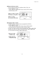
The external adjuster control increases the outlet air
temperature during cooling or decreases during heating.
Note 3
External adjuster control
Thermostat OFF
Setting value (Ts)
-1 ˚C
+1 ˚C
Setting value (Ts)
During cooling
During heating
Standard control
Standard control
External adjuster control
Thermostat OFF
Remote controller display
Pressure control
Standard pressure control
Standard control
Pressure control selection
External adjuster control
•If it is set at OFF (factory default), the remote control function is set.
17: Selection is made by the external adjuster control
Ԟ
Control mode switching
٨
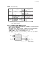
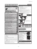
The control content of indoor units can be switched in following way. ( is the default setting)
Switch No. control content
SW1
Indoor unit address (tens place)
SW2
Indoor unit address (ones place)
SW3
Outdoor unit address (tens place)
SW4
Outdoor unit address (ones place)
SW5
㧙
1
OFF (Use always at OFF.)
Old and new Super Links are judged automatically.
SW5
㧙
2
Indoor unit address (hundreds place)
ԟ
Function of CNT connector of indoor printed circuit board
Ԡ
Control of total heat exchanger bypass damper during heating and cooling
٨
XR1 to XR4 are DC 12 V relays. (Omron LY2F or equivalent)
٨
XR5 is a DC 12, 24 or 100 V relay. (Omron MY2F or equivalent)
٨
CNT connector (Site side) – Maker, model
Connector: Molex 5264-06
Terminal: Molex 5263T
٨
Remote start/stop and monitoring kit is provided as an optional product.
٨
If it is necessary to connect the signal wire of the shunt current
controller for the Cooling/Heating Free Multi, connect the wire to
CNT or CNT2 according to the installation manual attached to the
shunt current controller.
٨
XR2 (heating output) has already been assembled.
This is used to interlock the operation of the humidifier of total
heat exchanger.
When the remote start/stop and monitoring kit is used, connect the
output from the kit (common output 2) to the terminal [3] or [4].
٨
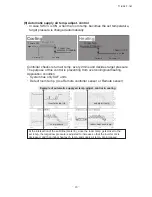
Suction temperature is used to control (ON/OFF) the
bypass damper of total heat exchanger.
٨
Relay output: DC 12 V relay (Omron Y2F or equivalent)
Switch No. control content
SW6
㧙
1 ~ 4 Model capacity setting
SW7
㧙
1 ON Operation check, Drain motor test run
OFF Normal operation
SW7
㧙
2 OFF Spare
SW7
㧙
3 OFF (Suction)/ON (Outlet) temperature control
SW7
㧙
4 OFF (Pressure control manual selection) /ON (Auto selection)
+12
Indoor units control box
(Blue 6P)
Printed circuit board
Remote start/stop kit
Note (1): Do not use the length over 2 meter
White
Black
Yellow
Blue
Brown
Orange
Orange
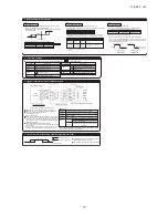
Input
power
Remote start / stop button or timer point
Output 1: Operation output (there is output when unit is in operation.)
Output 2: Heating output (there is output when operation MODE is HEATING.)
Output 3: Thermo ON output
Output 4: Inspection output (there is out put when unit is stopped by error.)
Input 5:
X
R5
OFF ON UNIT ON
X
R5
ON OFF UNIT OFF
X
R5
OFF ON Receiving pulse signal, "ON/OFF"
is reversed.
Factory set
Local set
Refer to instruction manuals of "Branching controller", when the indoor unit is
connected to "Heat recovery 3-pipe systems".
Note
CNT
Common
Output
Output
Output
Output
٨
Function
(Application coverage
0.75
㨪
1.25mm
2
)
Butt splice
Red
Black
Yellow
Blue
Brown
Orange
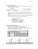
Suction temperature (ºC)
Suction temperature up
Suction temperature down
CnD:ON
10
12
16
18
CnD:OFF
CnD:OFF


