background image

-


-

'11•SAF-T-161

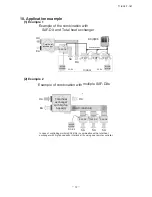
10. Application example

(1) Example 1

Example of the combination with 

SAF-DX and Total heat exchanger 

Total heat 

exchanger

SA

RA

EA

OA

SAF-DX

Remote

controller

FDT

FDT

FDT

KX(R)E6

Indoor

Refrigerant piping

Remote

controller

RC-E4

RC-E4

(2) Example 2

Example of combination with 

multiple SAF-DXs

Total heat 

exchanger

with big fan 

capacity

SA

RA

EA

OA

SAF-DX

SA

SA

SAF-DX

SAF-DX

RC-E4

In case of controlling multiple SAF-DXs in combination with a total heat 

exchanger with big fan capacity, interlock all by using one remote controller.  

Remote

controller

SA’(=return air)

Example of the combination with 

SAF-DX and Total heat exchanger 

Total heat 

exchanger

SA

RA

EA

OA

SAF-DX

Remote

controller

FDT

FDT

FDT

KX(R)E6

Indoor

Refrigerant piping

Remote

controller

RC-E4

RC-E4

Example of combination with 

multiple SAF-DXs

Total heat 

exchanger

with big fan 

capacity

SA

RA

EA

OA

SAF-DX

SA

SA

SAF-DX

SAF-DX

RC-E4

In case of controlling multiple SAF-DXs in combination with a total heat 

exchanger with big fan capacity, interlock all by using one remote controller.  

Remote

controller

SA’(=return air)

Summary of Contents for SAF-DX1000E6

Page 1: ...X1000E6 Fresh Air DX Assembly Models 1 Regarding the Outdoor unit series refer to the following table Note Reference manuals No Data book 09 KXR SM 130 Models 4㨪6HP 8㨪12HP 14㨪48HP Heat recovery 3 pipe ststems Technical manual Service manual 08 KX T 117 09 KX DB 124 09 KX SM 125 09 KX DB 127 09 KX SM 128 09 KXR DB 129 Manual No 11 SAF T 161 updated March 31 2011 ...

Page 2: ...tions 3 3 Exterior dimensions 4 4 Electrical wiring 13 5 Internal resistance characteristics 14 6 Range of usage limitations 15 7 Operation control function by the indoor controller 16 8 User s manual 22 9 Installation manual 23 10 Application example 32 ...

Page 3: ...as shown in following table Select SAF DX according to the processing air volume Mixed use of SAF DX with KX R E6 indoor unit is available Total connectable capacity of KX R E6 indoor units including SAF DX must be within 100 of outdoor unit capacity Connectable outdoor unit are all KX R E6 series 5 to 48HP All two wire remote controller are available and all center console also can be used Model ...

Page 4: ... control of total heat exchanger must be interlocked with SAF DX Both return air temp control and supply air temp control are applicable Switching the control method can be done with the Dip SW on the control PCB FAN OA EA SA RA SAF DX exchanger Total heat SAF DX Total heat exchanger SA RA EA OA supply fresh air Return fresh air temp sensor temp sensor interlock SW7 3 ON OFF Switching between retu...

Page 5: ...WDQGDUG QWHUQDO 5HVLVWDQFH 2XWVLGH DLU LQWDNH LU ILOWHU 4 W 6KRFN YLEUDWLRQ DEVRUEHU QVXODWLRQ QRLVH KHDW 2SHUDWLRQ FRQWURO 2SHUDWLRQ VZLWFK 5RRP WHPSHUDWXUH FRQWURO 6DIHW HTXLSPHQW QVWDOODWLRQ GDWD 5HIULJHUDQW SLSLQJ VL H RQQHFWLQJ PHWKRG 5HIULJHUDQW UDLQ XS NLW UDLQ KRVH QVXODWLRQ IRU SLSLQJ FFHVVRULHV SAF DX250E6 N 9ᨺ G PP NJ RXYHU ILQ LQQHU JURRYHG WXELQJ OHFWURQLF SDQVLRQ 9DOYH 0 3D 3RO XUHWK...

Page 6: ...E VP20 Contents Gas piping Symbol A φ9 52 3 8 Flare Outdoor air duct Air supply duct Inspection hole F G M10 C Label model name Hole for power source line Wiring hole for total enthalpy Hole for communication line Suspension bolts heat exchanger Liquid piping Drain piping Suspension bolts pitch Control box Suspension bolts pitch 373 337 18 18 362 70 70 PCH000Z367 3 Exterior dimensions 1 Without Dr...

Page 7: ...d service φ6 35 1 4 Flare B D E VP20 Contents Gas piping Symbol A φ12 7 1 2 Flare Outdoor air duct Air supply duct Inspection hole F G M10 C Label model name Hole for power source line Wiring hole for total enthalpy Hole for communication line Suspension bolts heat exchanger Liquid piping Drain piping Suspension bolts pitch Control box Suspension bolts pitch 373 337 18 18 362 70 70 Model SAF DX500...

Page 8: ...service φ6 35 1 4 Flare B D E VP20 Contents Gas piping Symbol A φ12 7 1 2 Flare Outdoor air duct Air supply duct Inspection hole F G M10 C Label model name Hole for power source line Wiring hole for total enthalpy Hole for communication line Suspension bolts heat exchanger Liquid piping Drain piping Suspension bolts pitch Control box Suspension bolts pitch 373 337 18 18 362 70 70 Model SAF DX800E6...

Page 9: ... duct Air supply duct A B G 710 250 270 190 160 C D 385 325 710 160 180 220 337 220 27 67 285 315 64 φ 2 5 0 2 φ 2 0 0 Inspection hole 450 100 200 822 450 F G M10 E F C 264 Label model name Hole for power source line Wiring hole for total enthalpy Hole for communication line Suspension bolts heat exchanger Liquid piping Drain piping Suspension bolts pitch Suspension bolts pitch 373 337 18 18 362 7...

Page 10: ...ts Gas piping Symbol A φ9 52 3 8 Flare Outdoor air duct Air supply duct Inspection hole F G M10 Hole for power source line Wiring hole for total enthalpy Hole for communication line Suspension bolts heat exchanger Liquid piping Drain piping Suspension bolts pitch Control box VP25 Notes 1 Drain piping C2 C1 Drain hose Option Local installation C2 Notes 1 Please local arrange connected socket for VP...

Page 11: ... A φ12 7 1 2 Flare Outdoor air duct Air supply duct Inspection hole F G M10 Hole for power source line Wiring hole for total enthalpy Hole for communication line Suspension bolts heat exchanger Liquid piping Drain piping Suspension bolts pitch Control box VP25 Notes 1 Drain piping C2 C1 1 Please local arrange connected socket for VP25 Drain hose Option Local installation C2 Notes C1 600 or less 29...

Page 12: ...Outdoor air duct Air supply duct Inspection hole F G M10 Hole for power source line Wiring hole for total enthalpy Hole for communication line Suspension bolts heat exchanger Liquid piping Drain piping Suspension bolts pitch Control box VP25 Notes 1 Drain piping C2 C1 Drain hose Option Local installation Notes 1 Please local arrange connected socket for VP25 C1 C2 600 or less 295 325 57 Label mode...

Page 13: ... 0 2 φ 2 0 0 Inspection hole 450 100 200 822 450 F G M10 E F 264 Label model name Hole for power source line Wiring hole for total enthalpy Hole for communication line Suspension bolts heat exchanger Liquid piping Drain piping Suspension bolts pitch Notes 1 Please local arrange connected socket for VP25 Drain hose Option Local installation C2 VP25 Notes 1 Drain piping C2 C1 C1 600 or less 295 325 ...

Page 14: ... 12 11 SAF T 161 PJZ000Z274 3 Remote controller Option parts Wired remote controller Model RC E4 ...

Page 15: ...hermistor Remote controller Thermistor Return air Thermistor Service air Thermistor Heat exchanger Relay for DM TB3 Terminal block Signal line mark SW7 2 Reserved SW7 3 SW7 4 Pressure setting XR1 XR2 XR3 XR4 XR5 Option 1 2 3 4 5 6 12 CNT X3 CNW0 RD X6 1 7 5 3 X1 X2 Control PCB DM CNR2 9 WH 3 1 Y BL Y X4 CNR CNI BL SW6 SW5 1 3 1 CNB SW2 SW1 SW4 SW3 SM 1 CNA 5 3 2 4 SW7 F 0 16A LED 3 LED 2 TB3 Y X Y...

Page 16: ...F T 161 SAF DX250E6 350E6 SAF DX500E6 SAF DX800E6 SAF DX1000E6 Air flow m3 h Internal resistance Pa 200 400 600 800 1000 1200 250 300 350 500 10 20 30 40 50 60 70 80 90 100 5 Internal resistance characteristics ...

Page 17: ... 15 11 SAF T 161 6 Range of usage and limitations SAF DX of the front cover 3 3 3 Refer to the front cover Refer to the front cover PCH000Z374 3 3 3 SAF DX of the front cover DX is DX is ...

Page 18: ...ils CND 7 Operation control function by the indoor controller 1 SAF DX Control Section 2 SAF DX Control PCB Signal line Remote controller line Return air temp sensor Supply air temp sensor Heat exchanger temp sensor RRT coil Float switch SAF DX control PCB Terminal block Control box for power cable 1 Total heat exchanger operation command Power line Single phase 220 240V 50Hz 1 The capacity of ind...

Page 19: ...2 should be kept OFF SAF DX Total heat exchanger SA RA EA OA return fresh air temp sensor supply fresh air temp sensor 3 SW7 Function setting 4 Switching return supply air temp control Supply air temp control is available as OA processing unit supply air temp sensor is already equipped When SW7 3 is Off it become return air temp control and indoor EEV is controlled to keep the superheat of heat ex...

Page 20: ... by RC E3 4 Thermo ON OFF control Temp difference between R A temp sensor or R C sensor and set temp by R C same as return air temp control Cooling Set return air temp must be greater than Target supply temp Heating Set return air temp must be less than Target supply temp If not Set temp becomes Target supply temp Return air temp Set R A temp Supply air temp Target S A temp Return air temp control...

Page 21: ... 1 0㷄 Offset 1 0㷄 Offset 1 5㷄 Offset 2 0㷄 Offset 4 0㷄 Offset 3 0㷄 Offset 2 0㷄 Offset 2 0㷄 Offset 3 0㷄 Offset 4 0㷄 Actual meaning Indoor unit function 㪩㪼㫋㫌㫉㫅㩷㪘㫀㫉㩷㪫㪼㫄㫇㪅 09 㪫㪸㫉㪾㪼㫋㩷㫊㫌㫇㫇㫃㫐㩷㪸㫀㫉 㫋㪼㫄㫇㪅㩷㫆㪽㪽㫊㪼㫋㩷 Target supply air temp in heating 36㷄 Target high pressure HP㻍2 75MPa Target supply air temp can be set from 32㷄 to 40㷄 㷄 at 1㷄 step 䃨 Factory default Target supply air temp in cooling 15㷄 Target lo...

Page 22: ...se Remote controller sensor or Remote sensor supply air temp At the intersection of the solid line mark since the room temp gets closer to the set temp the target low pressure is adjusted to increase so that the inverter Hz is decreased and then indoor heat exch temp and supply air temp are increased Example of automatic supply air temp adjust control in cooling Inverter actual Hz Low pressure Ind...

Page 23: ...ault 䋨㷄䋩 䋨㷄䋩 䋨㷄䋩 10 Free cooling function Free cooling is the function to control the opening of the by pass damper of total heat exchanger in cooling By pass damper of the total heat exchanger can be controlled by CnD CND on PCB outputs ON OFF signal according to outdoor temp return temp When using this function the return air temp sensor should be relocated to the position where the outdoor air ...

Page 24: ... setting temperature of the remote controller indicates the outdoor temperature while operating thermostat ON OFF OPERATION MODE select button Dehumidifying operation is prohibited for SAF DX Every time this button is pressed N displays switch as below For the outdoor unit with Duct connected High static pressure outdoor air processing unit FDU F and Fresh Air DX Assembly SAF DX operation in dehum...

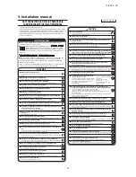
Page 25: ...re electrical wiring work It could cause electric shock unit failure and improper running ٨ Perform earth wiring surely Do not connect the earth wiring to the gas pipe water pipe lightning rod and telephone earth wiring Improper earth could cause unit failure and electric shock due to a short circuit ٨ Earth leakage breaker must be installed If the earth leakage breaker is not installed it can cau...

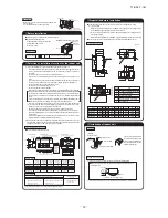
Page 26: ...with the water surface as illustrated below ٤If the unit is not leveled it may cause malfunctions or inoperation of the float switch M10 nut Suspension bolt Spring washer for M10 Unit Washer for M10 Pipe side Pour water Water surface 0 5mm Vinyl hose Let the pipe side be slightly sloped If the measurements between the unit and the ceiling hole do not match upon installation it may be adjusted with...

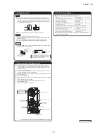
Page 27: ...reover the air outlet should be able to adjust the air flow volume ԚAn access hole must be provided at the ceiling It is indispensable to maintain electrical equipment motor and functional items and to wash the heat exchanger ԛDuct must be heat insulated to prevent dewing Necessary thickness of insulator is 65 mm JIS A9501 Humidifier Air outlet Direct expansion coil kit Total heat exchanger with h...

Page 28: ...erly done Water leakage Does the air flow falls within the range of It cannot cool or warm Water is drained properly Water leakage Supply voltage is same as mentioned in the model name plate PCB burnt out not working at all There is mis wiring or mis connection of piping PCB burnt out not working at all Earth wiring is connected properly Electric shock Cable size comply with specified size PCB bur...

Page 29: ...fitting may cause abnormal heat and fire ٨Use the genuine optional parts And installation should be performed by a specialist If you install the unit by yourself it could cause water leakage electric shock and fire ٨Do not repair by yourself And consult with the dealer about repair Improper repair may cause water leakage electric shock or fire ٨Consult the dealer or a specialist about removal of t...

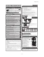
Page 30: ...f trial cooling operation Remote controller line No polarity Remote controller line No polarity Operate the remote control unit as follows 1 Starting a cooling test run ԘStart the system by pressing the button ԙSelect Cool with the MODE button ԚPress the TEST button for 3 seconds or longer The screen display will switch to ԛWhen the SET button is pressed while is indicated a cooling test run will ...

Page 31: ...n is by degree F The filter sign is indicated after running for 180 hours The filter sign is indicated after running for 600 hours The filter sign is indicated after running for 1000 hours The filter sign is indicated after running for 1000 hours then it will be stopped by compulsion after 24 hours Make permission prohibition control of function be in effect With the VRF series it is used to stop ...

Page 32: ... function is set 17 Selection is made by the external adjuster control Ԟ Control mode switching ٨The control content of indoor units can be switched in following way is the default setting Switch No control content SW1 Indoor unit address tens place SW2 Indoor unit address ones place SW3 Outdoor unit address tens place SW4 Outdoor unit address ones place SW5㧙1 OFF Use always at OFF Old and new Sup...

Page 33: ...ppen and the data can be confirmed by remote controller Operating procedure 1 Press the button The display change 2 Once press the button and the display change 3 Press the SET button and abnormal operation data mode is started 4 When only one indoor unit is connected to remote controller following is displayed ԘThe case that there is history of abnormal operation Error code and is displayed Examp...

Page 34: ...th multiple SAF DXs Total heat exchanger with big fan capacity SA RA EA OA SAF DX SA SA SAF DX SAF DX RC E4 In case of controlling multiple SAF DXs in combination with a total heat exchanger with big fan capacity interlock all by using one remote controller Remote controller 㹢SA return air Example of the combination with SAF DX and Total heat exchanger Total heat exchanger SA RA EA OA SAF DX Remot...

Page 35: ...tioning Refrigeration Systems 16 5 Konan 2 chome Minato ku Tokyo Japan Fax 03 6716 5926 Because of our policy of continuous improvement we reserve the right to make changes in all specifications without notice Copyright MITSUBISHI HEAVY INDUSTRIES LTD c ...

Reviews: