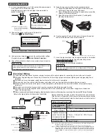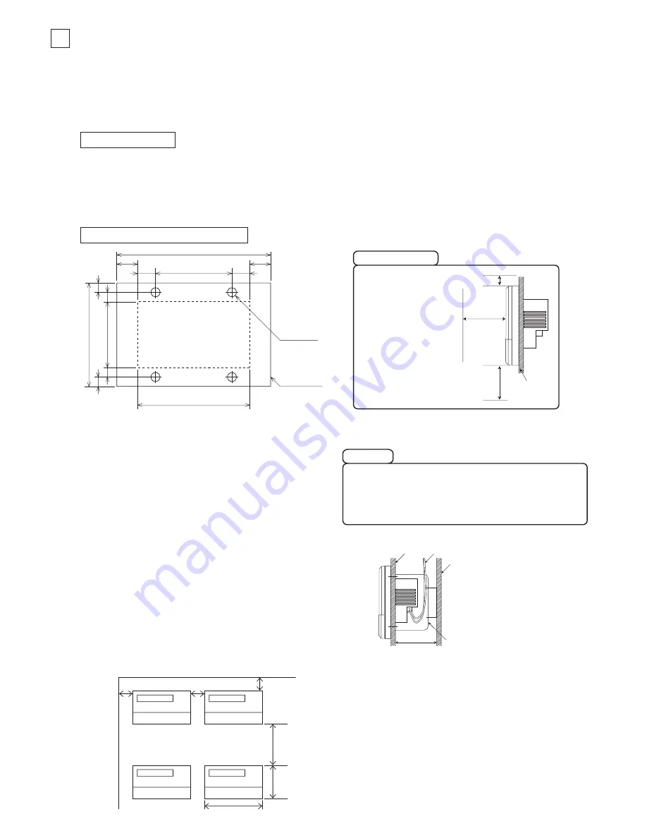
Internal wall
Lead-in wires
Building's wall
50mm or more
Electrical box
(prepared on site)
50mm or
more
50mm or
more
50mm or
more
150mm or
more
120mm
215mm
Caution
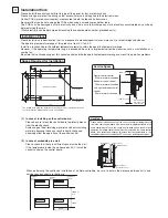
(2) In case of embedding in a wall
Please be sure to lock the control board to protect persons
from the electric shock.
Avoid usage of heat-retaining materials and heat-insulating
materials because these can result in heat buildup and
adversely affect the operation of the central control.
When performing the continued installation of multiple controllers, be sure to obtain the distance between units and
service space as shown in the figure.
(1) In case of installing on the control board
Please check that there is sufficient space inside the wall.
If the temperature inside the wall exceeds 40
°
C
, install the
central control on the control board.
Please do not install devices that can cause the ambient temperature to
rise in the same control board. Also, do not install multiple controllers in the
same control board. These can cause heat to build up and result in false
operation. If multiple central control must be installed in the same control
board, take corrective measures to ensure that the temperature in the
control board does not rise above 40
°
C such as by installing cooling fans.
The dotted lines show the installation opening section for installation on the
control board (the dimensions are only an example).
Installation opening
90
120
7.5
(7.5)
8
7
152
215
13
(13)
178
M4 pilot hole
4 locations
Central control
outline
(18.5)
18.5
50mm or more
500 mm or more
150mm or more
Internal wall or
front side of the
control board
3
Installation Work
Installation Place
Space Required for Installation
Please install the central control after turning off the power for fear of electric shock.
Please arrange or protect the wiring so that excessive force is not applied to the electrical wires.
Control PCBs (printed circuit boards) are mounted to both the top and bottom cases.
Be careful that you do not damage the PCBs when using a screwdriver and other tools.
The PCBs can be damaged by static electricity, and so be sure to discharge any static electricity accumulated on your body
before starting the work.
(Static electricity can be discharged by touching the control board and other grounded parts.)
Please install in an indoor location that is not exposed to electromagnetic waves, water, dust, or other foreign substances.
The operating temperature range of this product is from 0
°
C to 40
°
C.
Install in a location where the ambient temperature remains within the operating temperature range.
However, if the operating temperature range is exceeded, be sure to implement corrective measures such as installation of a
cooling fan.
Be aware that continued usage of this central control outside the operating temperature range can result in operation problems.
Front of central control
500mm or more is needed
Bottom of central control
150mm or more is needed
Left, right and top of central
control
50mm or more is needed
Service Space

