background image

– 18 –

Item

Feature

Color

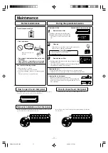
Stop the unit and turn off the power switch.

The unit uses appr. 2W even when the power switch has been turned
off during the off-season for safety or for saving energy.

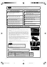
At the beginning of the season

Ensure that nothing has snapped and that the
earthed flex is not disconnected.

Make certain that there are no obstacles blocking the
air flow around the air intake and outlet openings of
the indoor and outdoor units.

NOTE

Cooling/heating is affected by an air filter clogged up with dust etc., and the operation noise becomes louder. It may also
use extra electricity. Please clean the air filter at appropriate intervals.

1

2

Remove batteries from the remote control.

Clean both the indoor and outdoor units.

Clean and reinstall the air filters.

Perform the fan operation for a half day.

Dry the inside of the unit.

3
4
5

Check the installation base for corrosion or rust.

Insert batteries in the remote control.

Turn on the power switch.

Ensure that the air filters are clean.

1

2
3
4
5
6

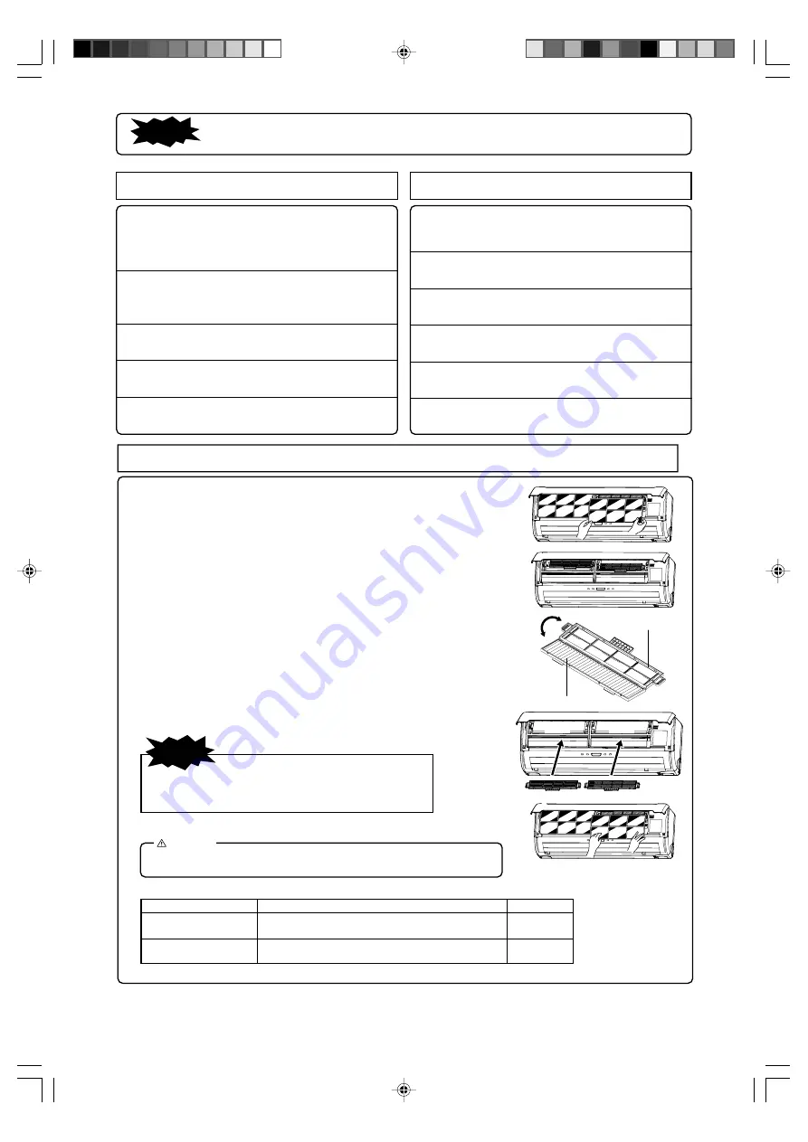
   Installing, inspecting, and replacing the air-cleaning filter

Filter

Filter holder

For replacement the air-cleaning filter, contact your dealer.

Sources of odors on the filter are broken up, resulting in a
deodorizing effect.

Photocatalytic washable
deodorizing filter

Orange

Install

Install

At the end of the season

By using the work of enzyme, mold and bacteria on the filter
are destroyed and the room air is kept clean.

Natural enzyme filter

Green

1. Open the air inlet panel and remove the air filters.

2. Remove the filter holders, with the air-cleaning filter installed in the folders, from the air-

conditioner.

3. Remove the photocatalytic washable deodorizing filter from the filter  holder and inspect

the filter. Periodically, remove any dust or dirt from the photocatalytic washable deodoriz-
ing filter. If the photocatalytic washable deodorizing filter is particularly dirt, it may be
washed with water. However, the filter is fragile so be sure to wash it installed in the filter
holder to avoid damaging it. After washing the filter, place it in sunlight to dry. Placing the
filter in sunlight revitalizes the deodorizing effect.

Remove the natural enzyme filter from the filter holder and inspect the filter. Use a vacuum
cleaner to remove any dust or dirt from the natural enzyme filter. Replace the natural en-
zyme filter if it cannot be cleaned or if it has been used for about 1 year.
(The natural enzyme filter should be replaced after about 1 year of use. However, the actual
replacement period may vary depending on the conditions in which the filter is used.)

(Do not dispose of the filter holders. They are reused. )

4. Install the air-cleaning filter in the filter holders, and then install the filter holders in the

air-conditioner.

5. Install the air filters and closed the air inlet panel.

NOTE

The natural enzyme filter and the photocatalytic washable
deodorizing filter may be installed on either the right or left side of
the air-conditioner.

CAUTION

Do not expose natural enzyme filters to direct sunlight for an extended period. The bacteriolytic
effect will be lost.

RWA012A246_En.p65

06.9.22, 7:37 PM

18

Summary of Contents for SKM20ZG-S

Page 1: ... KL MA ENGLISH DEUTSCH ITALIANO ESPAN OL NEDERLANDS PORTUGUÊS π РУССКИЙ TÜRKÇE FRANÇAIS This air conditioner complies with EMC Directive 89 336 EEC LV Directive 73 23 EEC Ce climatiseur est conforme à la Directive EMC 89 336 EEC LV Directive 73 23 EEC Dieses Kimagerät erfüllt die EMC Direktiven 89 336 EEC LV Direktiven 73 23 EEC Questo condizionatore d aria è conforme alla Direttiva EMC 89 336 EEC...

Page 2: ...djustment during AUTO 7 About FAN SPEED 7 COOL HEAT DRY FAN mode operation procedure 8 Air conditioner operating conditions 8 Characteristics of HEAT mode operation 8 Air flow direction adjustment procedure 9 3D AUTO operation procedure 9 SLEEP operation procedure 10 OFF TIMER operation procedure 10 ON TIMER operation procedure 11 SLEEP operation ON TIMER operation procedure 11 PROGRAM TIMER opera...

Page 3: ...n engineering workplace the equipment may function poorly It is not advisable to install the system yourself as faulty handling may cause leakage of water electric shock or fire Gas leaks may cause fire If you don t fit a circuit breaker you may cause an electric shock Negligence may cause flooding in the room resulting in wet furniture Earth cables should never be connected to a gas pipe municipa...

Page 4: ...ou don t repair any damage straightaway the unit may fall down and cause personal injury Failure to observe this may result in injury Condensation falling from the unit can stain objects and cause accidents or electrical shock Insufficient ventilation may cause accidents due to oxygen deficiency Failure to observe this may result in injury through insecure objects top pling over Never clean the un...

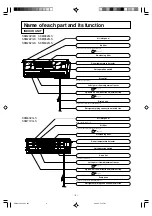
Page 5: ...tor Air cleaning filter Refrigerant piping connection electric flex SKM28ZG S SKM35ZG S SKM50ZG S SKM20ZG S SKM22ZG S SKM25ZG S Air filter Removes dust or dirt from the inlet air Page 17 Drain hose Drains water from the dehumidified air Left right air flow adjustment louver Page 9 Up down air flow direction adjustment flap Page 9 Air outlet Air blows out of here Unit operation switch Room temperat...

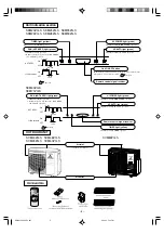
Page 6: ...iver Unit ON OFF button TIMER light yellow Illuminates during TIMER operation Air inlet on side rear surface Air outlet Remote control signal receiver 3D AUTO light green Illuminates during 3D AUTO operation HI POWER light green Illuminates during HIGH POWER operation RUN HOT KEEP light green Illuminates during operation Blinks at air flow stop due to the HOT KEEP and CLEAN operation Page 20 HOT K...

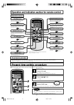
Page 7: ...tically set to time setting mode Example Set to 10 30 Press the ACL switch Press with the tip of a ballpoint pen etc The time indicator blinks and can be set to the current time Press the or button Set to 10 30 Press the ON OFF button The indication changes from blinking to steady lighting and the setting is complete The timer operation is set on the basis of the present time so please set it cor ...

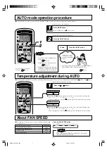
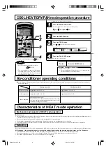
Page 8: ... be operated by simply pressing the ON OFF button To stop Press the ON OFF button Each time the button is pressed the switch over occurs in the following order 6 5 1 0 1 6 When 6 is indicated even if the button is pressed the indicator does not change Each time the button is pressed the switch over occurs in the following order 6 5 1 0 1 6 When 6 is indicated even if the button is pressed the indi...

Page 9: ...pens the automatic defroster is activated and during defrosting the heating operation stops for 5 to 10 minutes Both indoor and outdoor fans stop and the RUN light green blinks slowly 1 5 sec ON 0 5 sec OFF during defrosting The outdoor unit may give off some steam during defrosting This is to help the defrosting process and is not a defect The HEAT operation resumes as soon as defrosting has been...

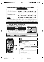
Page 10: ... or DRY operation do not operate for hours on end with the air flow blowing straight down Otherwise condensation may appear on the outlet grill and drip down Do not try to adjust the flaps and louvers by hand as the control angle may change or the flap or louver may not close properly HEAT Horizontal blowing Slant forward blowing COOL DRY Recommended angle of the flap when stopping When heating op...

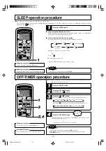
Page 11: ...NCEL button to turn off the SLEEP indicator Changing of set time Set to a new time by using SLEEP button Cannot be set at the same time as OFF TIMER NOTE OFF TIMER operation procedure The unit stops automatically at the end of the set period of time If it is stopped perform the operations starting with STEP 1 and if running start with STEP 2 Example You wish it to stop 22 30 Press the ON OFF butto...

Page 12: ...ting of the timer light yellow of this unit is complete h After the SLEEP operation set time has elapsed the operation stops and it starts from 5 to 60 minutes before the ON TIMER s time The timer light is not lit at the ON TIMER s time Changing of set time Set a new time by using the SLEEP or ON TIMER button Releasing procedure Press the CANCEL button to turn off the timer indicator Press the or ...

Page 13: ...hanism The room temperature is checked 60 minutes before the timer is at ON Depending on the tempera ture at that time the operation starts 5 to 60 minutes before the timer is at ON The Amenity facility only func tions for COOL and HEAT op eration mode including AUTO It does not work for DRY mode About SLEEP operation In COOL operation Stop Operation starts Check the room temp 60 mins in advance S...

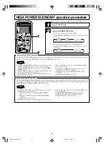
Page 14: ...mer operation HIGH POWER operation will start when the ON time is reached When the following operations are conducted HIGH POWER op eration will be canceled 1 When the HI POWER ECONO button is pressed again 2 When the operation mode is changed 3 When it has been 15 min since HIGH POWER operation has started 4 When the 3D AUTO button is pressed Concerning ECONOMY operation Pressing the HI POWER ECO...

Page 15: ...nit ON OFF button it stops if you press the button again Unit ON OFF button Do not hold the Unit ON OFF button down for more than 5 seconds Holding it down longer than 5 seconds sets the automatic cooling used during servicing or when moving the air conditioner NOTE CLEAN operation is impossible after HEAT and FAN OFF TIMER and SLEEP operations have stopped The indoor unit fan runs for about two h...

Page 16: ...matically resumes operations at that point after the power has been restored The following settings will be cancelled 1 Timer settings 2 HIGH POWER operations NOTE The power blackout auto restart function is set at on when the air conditioner is shipped from the factory Consult with your dealer if this function needs to be switched off When power failure occurs the timer setting is cancelled Once ...

Page 17: ...ogether Remove the batteries when the remote control is not used for a long period The life of a battery conforming to JIS or IEC should be 6 to 12 months with normal use If used longer or when an unspecified battery is used liquid may leak from the battery causing the remote control to malfunction On the battery is printed its expected life This may be shorter than that of the air conditioner dep...

Page 18: ...ishing agents etc They may deform or scratch the unit Don t spill water Do not touch the aluminum fins on the heat exchanger Stand firmly on a stepladder or other stable object when removing the inlet panel and filter Cleaning If the filter is very dirty clean it with warm water approx 30 C and dry it thoroughly CAUTION Don t clean the filters with boiling water Don t dry them over an open flame P...

Page 19: ...pen the air inlet panel and remove the air filters 2 Remove the filter holders with the air cleaning filter installed in the folders from the air conditioner 3 Remove the photocatalytic washable deodorizing filter from the filter holder and inspect the filter Periodically remove any dust or dirt from the photocatalytic washable deodoriz ing filter If the photocatalytic washable deodorizing filter ...

Page 20: ...s are required Suitable installation position Is there any obstruction in front of the indoor unit preventing proper ventilation and functioning Don t install the unit in any of the following places Where there is a danger of leaking inflammable gases Where there is substantial splashing of oil Malfunctioning due to corrosion may occur if the unit is installed in a spa where sulfide gases are gene...

Page 21: ...ven if power has been re stored unless you have the power blackout auto restart function The memory circuit of the microcomputer has been wiped out Use the remote control to start the operation again Remote control signals are not received Moisture may form on the air outlet grills There is a slight smell Air blown out during operation may smell This is caused by tobacco or cosmetics sticking to t...

Page 22: ...hat was operated first will be given priority so the air conditioner that is operated after that will conduct air blowing operation When you want to give priority to the air conditioner that was started later either stop the air conditioner that has priority or cause the operation type of the unit operated first to match that of the unit operated second Automatic Operation When the remote control ...

Page 23: ...it on power transistor closed service valve Current cut 2 time flash 3 time flash 1 time flash Over heat of power transistor Over heat of compressor 4 time flash 5 time flash RUN light ON Broken power transistor broken compressor wire Broken discharge pipe sensor wire poor connector connection Compressor blockage Overload operation overcharge Cooling problem Gas shortage defective discharge pipe s...

Page 24: ...ССКИЙ TÜRKÇE This air conditioner complies with EMC Directive 89 336 EEC LV Directive 73 23 EEC Ce climatiseur est conforme à la Directive EMC 89 336 EEC LV Directive 73 23 EEC Dieses Kimagerät erfüllt die EMC Direktiven 89 336 EEC LV Direktiven 73 23 EEC Questo condizionatore d aria è conforme alla Direttiva EMC 89 336 EEC LV Direttiva 73 23 EEC Deze airconditioner voldoet aan EMC Directive 89 33...

Reviews: