background image

CRAE0176

20

17

18

21

23

22

24

25

14

15

16

9

10

11

12

13

1

8

5

7

6

4

2

3

19

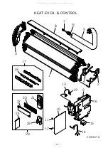
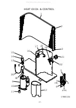
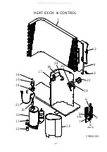
HEAT EXCH. & CONTROL

- 35 -

All manuals and user guides at all-guides.com

Summary of Contents for SRC10CFV-4

Page 1: ...CONDITIONING TECHNICAL MANUAL PARTS LIST WALL MOUNTED TYPE ROOM AIR CONDITIONER Split system air cooled cooling only type SRK10CFV 4 13CFV 4 All manuals and user guides at all guides com a l l g u i d e s c o m ...

Page 2: ...TECHNICAL MANUAL All manuals and user guides at all guides com ...

Page 3: ...operation 12 4 7 Timer operation 13 4 8 Installation location setting 14 4 9 Outline of cooling operation 15 4 10 Outline of dehumidifying operation 16 4 11 Outline of automatic operation 17 4 12 Outline of fan operation 17 4 13 Outline of clean operation 17 4 14 Protective control function 18 5 APPLICATION DATA 19 5 1 Selection of location for installation 20 5 2 Installation of indoor unit 21 5 ...

Page 4: ...re automatically controlled allowing the entire room to be efficiently conditioned Memory flap Once the flap louver position is set the unit memorizes the position and continues to operate at the same position from the next time 2 Automatic operation When the remote control switch is set on auto it will either automatically decide operation mode such as cooling and thermal dry or operate in the op...

Page 5: ... kg R22 0 9 Pre Charged up to the piping length of 7 5m Refrigerant oil R 0 35 SUNISO 4GSI or ATMOS NM56 Air handling equipment Tangential fan 1 Propeller fan 1 Fan type Q ty Motor W 16 14 Air flow at High CMM 9 0 26 5 Air filter Q ty Polypropylene net washable 2 Shock vibration absorber Cushion rubber for compressor Electric heater Operation control Wireless Remote control Operation switch Room t...

Page 6: ...NISO 4GSI or ATMOS NM56 Air handling equipment Tangential fan 1 Propeller fan 1 Fan type Q ty Motor W 16 22 Air flow at High CMM 9 5 29 5 Air filter Q ty Polypropylene net washable 2 Shock vibration absorber Cushion rubber for compressor Electric heater Operation control Wireless Remote control Operation switch Room temperature control Microcomputer thermostat Pilot lamp RUN Green TIMER Yellow HI ...

Page 7: ...re Upper lower limits Vertical height difference between outdoor unit and indoor unit Max 5m Outdoor unit is higher Max 5m Outdoor unit is lower Item Models 1 Indoor unit Models SRK10CFV 4 13CFV 4 Unit mm Piping hole ø65 Piping hole ø65 53 5 380 6 Pipng for Liquid 448 6 ø6 35 10 ø9 52 13 ø12 7 Pipng for Gas Drain hose 520 ø16 53 5 44 5 252 2 7 5 8 3 102 5 585 102 5 133 5 450 206 5 202 450 138 44 5...

Page 8: ...ling cycle Heat exchanger Compressor Capillary tube Accumulator Service valve Gas Capillary tube Piping Gas 10 ø9 52 13 ø12 7 Unit mm Terminal block 10 ø9 52 3 8 13 ø12 7 1 2 ø6 35 1 4 Flare connecting Service valve Gas Service valve Liquid Flare connecting Drain holes 2 16 12 138 4 4 0 61 9 18 9 165 1 510 104 9 439 1 111 4 99 4 349 5 313 1 43 1 290 12 50 350 23 5 312 5 14 33 5 4 0 42 5 95 9 14 54...

Page 9: ...e indoor and outdoor units 14 16 18 20 22 15 20 25 30 35 40 0 6 0 7 0 8 0 9 1 0 1 1 1 2 1 3 43 24 ISO T1 Standard Condition Indoor air W B temperature C W B Cooling Applicable range Coefficient of cooling capacity in relation to temperature Cooling operation Outdoor air D B temperature C D B Piping length m Cooling 7 1 0 10 0 99 15 0 975 How to obtain the cooling capacity Example The net cooling c...

Page 10: ...ts name Symbol Parts name CC Capacitor for CM SM Flap motor CFI Capacitor for FMI Th1 2 Sensor LM1 2 Louver motor CFO Capacitor for FMO T Terminal block CM Compressor motor ZNR Varistor F Fuse 51C Motor protector for CM FMI Fan motor Indoor unit 52C Magnetic contactor for CM FMO Fan motor Outdoor unit Meaning of marks Notes 1 denotes magnetized relay denotes demagnetized relay 2 Th1 is room temper...

Page 11: ... button This button sets 3D AUTO operation This button cancels the ON timer OFF timer and SLEEP operation CANCEL button RESET switch Switch for resetting microcomputer and setting time SLEEP indicator Indicates during SLEEP operation TEMPERATURE indicator Indicates set temperature Does not indicate temperature when operation mode is on AUTO FAN SPEED indicator Indicates set air flow rate with lamp...

Page 12: ...ECONO HI POWER light green Illuminates during HIGH POWER operation Unit ON OFF button 4 2 Unit ON OFF button When the remote control batteries become weak or if the remote control is lost or malfunctioning this button may be used to turn the unit on and off 1 Operation Push the button once to place the unit in the automatic mode Push it once more to turn the unit off 2 Details of operation The uni...

Page 13: ... AUTO RESTART is cut auto restart is disabled See the diagram at right Jumper wire J7 4 4 Custom cord switching procedure If two wireless remote controls are installed in one room in order to prevent wrong operation due to mixed signals please modify the printed circuit board in the indoor unit s control box and the remote control using the following procedure Be sure to modify both boards If only...

Page 14: ...Auto HIGH POWER Other than Auto Setting fan speed Setting fan speed STEP1 STEP2 STEP3 STEP4 Left louver The left louver and right louver operate in the same direction left and right The left louver and right louver operate in opposite directions to each other on the left and right sides The left louver and right louver operate in opposite directions to each other on the left and right sides Right ...

Page 15: ...ration is selected the comfortable timer starts and determines the starting time of next operation based on the initial value of 15 minutes and the relationship between the room temperature at the setting time temperature of room temperature sensor and the setting temperature Max 60 minutes Operation mode Operation start time correction value Min 3 Room temp Setting temp 1 Room temp Setting temp 3...

Page 16: ... for 5 seconds or more The installation location display illuminates 3 Setting the air conditioning installation location Press the AIR FLOW LEFT RIGHT button and adjust to the desired location Each time the AIR FLOW LEFT RIGHT button is pressed the indicator is switched in the order of 4 Press the ON OFF button The air conditioner s installation location is set Press within 60 seconds of setting ...

Page 17: ...rature is not adjusted during the HIGH POWER operation 2 Protective functions will actuate with priority even during the HIGH POWER operation Indoor fan motor Flap and louver Display 52C Outdoor fan motor ON ON or OFF Lights up OFF OFF ON ON or OFF Lights up ON ON OFF Stop position control Lights up or flashes OFF OFF When the compressor command is OFF When the compressor command is ON When the co...

Page 18: ...door fan Speed 2 Indoor fan Start Temperature check Start Temperature check Compressor and outdoor fan Indoor fan Operation block decision C D Block A B Block minutes minutes Speed 2 Speed 1 20 seconds ON OFF OFF 0 4 8 ON OFF OFF 0 8 Compressor and outdoor fan Indoor fan D Block Compressor and outdoor fan Indoor fan C Block Compressor and outdoor fan Indoor fan B Block Compressor and outdoor fan I...

Page 19: ...stops if auto operation is started or if you switch to auto operation during manual operation the system runs in the previous operation mode 3 The temperature is checked 1 time in 30 minutes after the start of operation and if the judgment differs from the previous operation mode the operation mode changes 4 Setting temperature can be adjusted within the following range There is the relationship a...

Page 20: ...rmal operation is effective However stopping the compressor via a stop signal or protection control has priority 3 Self diagnosis function When something abnormal happens on the outdoor unit indoor unit fan motor and each sensor heat exchanger room temperature it will be indicated by flashing lights a Abnormality of outdoor unit When the indoor heat exchanger temperature does not fall to 25 C or b...

Page 21: ...llment execution can be the cause of electric shocks and fires Accurately connect wiring using the proper cable and insure that the external force of the cable is not conducted to the terminal connection part through properly securing it improper connection or securing can result in heat generation or fire Take care that wiring does not rise upward and accurately install the lid service panel It s...

Page 22: ...can be secured d A place where vibration will not be enlarged Avoid installing in the following places A place near the bedroom and the like so that the operation noise will cause no trouble A place where there is possibility of flammable gas leakage A place exposed to strong wind e Do not install the unit near the seaside or where there is possibility of chlorine gas generation Model All models I...

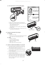
Page 23: ...ide Outdoor side Cut off the sleeve collar in case of drawing piping out to rear Cut off the sleeve collar that can be seen from beneath the unit Wall thickness 1 5 cm Indoor side Outdoor side Turn to tighten Paste View of sleeve when installed Inclined flange Sealing plate Sleeve Indoor side Outdoor side Look for the inside wall structures Intersediate support or pillar and firaly install the uni...

Page 24: ... before stretching it and shaping it Tape only the portion that runs through the wall Always tape the crossover wires with the pipe d Cautions when piping from the left and the rear center of the unit Top View Loosen and remove the spring type clamp Remove with your hand or a pair of pliers Use a hexagonal wrench to correctly insert the drain cap which was removed in 2 Caution Be careful because i...

Page 25: ...hment attachment of air inlet panel a To open pull the panel at both ends of lower part and release latches then pull up the panel until you feel resistance The air inlet panel stops at approx 60 open position b To close hold the panel at both ends of lower part to lower downward and push it slightly until the latch works then push the center portion slightly c To remove pull up the panel to the p...

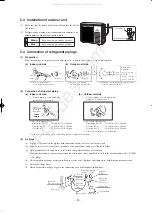
Page 26: ...it 1 Make sure that the unit is stable in installation Fix the unit to stable base 2 Perfrom wiring making wire terminal numbers conform to ter minal numbers of indoor unit terminal block 5 4 Connection of refrigerant pipings 1 Preparation Keep the openings of the pipes covered with tapes etc to prevent dust sand etc from entering them a Indoor unit side b Outdoor unit side 2 Connection of refrige...

Page 27: ...er and seal them If neglecting to do so moisture occurs on the piping and water will drip out b Finishing and fixing 1 Tie up the piping with wrapping tape and shape it so that it conforms to which the pipe is attached 2 Fix them with clamps as right figure 5 5 Installation of remote control switch 1 Mounting method of battery Uncover the remote control switch and mount the bat teries R03 AAA Micr...

Page 28: ...15 Running current A 3 4 4 9 b When manipulating the remote control mounted on a wall Make sure that it works normally i e transmission reception signal is audible before mounting Notes 1 The remote control is correctly facing the sensing element of the air conditioner when being manipulated 2 The typical coverage is indicated in the left illustration It may be more or less depending on the instal...

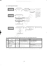
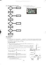
Page 29: ...f the power source and turn it on again in about 1 min and turn the unit on again YES No YES YES Does the trouble occur again Disconnect connectors and connect them again Operate the unit again after confirming that the fuse and the varistor equipped on PCB does not burn out Carry out checks according to detailed check process See later page Unit did not cool etc Is the power on Is the thermostat ...

Page 30: ...t circuit Resistance value kΩ Temperature C Is connection to connector good Is sensor resistance value normal Replace PCB Repair connector Replace sensor No No Yes Yes Chart for sensor temperature resistance characteristics 3 Troubleshooting Abnormality of outdoor unit Compressor malfunction of insufficient gas refrigerant Abnormality of indoor fan motor Fan motor defective printed circuit board d...

Page 31: ...otor Replace capacitor Abnormal Yes Normal Unit sensor Operation Function Short circuit Broken connection Cooling Cooling Indoor unit Room temperature sensor 1 Th1 except for continuous thermal setting Cooling will not operate FMI continuous operation CM FMo stopped Cooling will operate Heat exchanger frost preventer begins to operate Cools alternately for 10 minutes stopping for 3 minutes 5 Troub...

Page 32: ...normal YES Again pushing operating switch Operating the unit NO Does operating Unit ON OFF button YES Replace the display Remote control defects Abnormal is not fount It is normal Remote control defects NO NO YES NO Note 1 How to check the remote control a Press the reset switch of remote control b If the almost normal if entire display of remote control is shown after 1 indication Liquid side Gas...

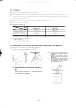
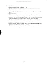
Page 33: ...3 after discharging air from the charge hose A then the gas refrigerant begins flowing from the cylinder into the unit Be sure to erect the refrigerant cylinder upright to let gas refrigerant flow into the unit f When refrigerant has been charged into the system to some extent refrigerant flow becomes stagnant when that happens start the compressor in cooling cycle until the unit is filled with ga...

Page 34: ...PARTS LIST INDOOR UNIT SRK10CFV 4 SRK13CFV 4 OUTDOOR UNIT SRC10CFV 4 SRC13CFV 4 All manuals and user guides at all guides com ...

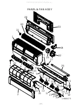
Page 35: ...CRAE0175 14 14 9 8 14 10 10 12 12 18 20 2415 22 11 21 17 22 13 2 4 5 5 1 31 28 30 35 35 6 3 4 16 22 25 21 19 23 7 27 26 32 34 33 29 PANEL FAN ASSY 33 All manuals and user guides at all guides com ...

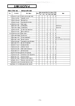
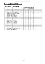
Page 36: ...5 RKX 129A 010 BRACKET MOTOR A 1 1 1 1 2 16 RKX 129A 011 BRACKET MOTOR B 1 1 1 1 2 17 RKX 129A 012 BRACKET MOTOR C 1 1 1 1 2 18 RKX 144A 001 LINK 1 1 1 1 2 19 RKX 144A 002 CRANK A 1 1 1 1 2 20 RKX 144A 003 CRANK B 1 1 1 1 2 21 RKW 144A 204 CRANK C 2 1 1 1 2 22 SSA 512T 052 MOTOR STEPPING 3 1 1 1 2 FOR FLAP LOUVER R L 23 RKS 504A 100G HARNESS ASSY 1 1 1 1 2 FOR FLAP 24 RKS 504A 100 HARNESS ASSY 1 1...

Page 37: ...CRAE0176 20 17 18 21 23 22 24 25 14 15 16 9 10 11 12 13 1 8 5 7 6 4 2 3 19 HEAT EXCH CONTROL 35 All manuals and user guides at all guides com ...

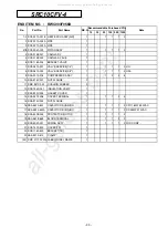
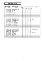
Page 38: ...SE CURRENT 1 1 1 2 4 F 3 15A 13 SSA 551A 163L SENSOR ASSY 1 1 1 2 4 INCL SENSOR ROOM TEMP HEAT EXCH 14 RKV 504A 500 HARNESS ASSY POWER 1 1 1 1 2 15 SSA 561B 713 BLOCK TERMINAL 1 1 1 2 2 16 RKX 011G 001 LABEL WIRING 1 17 RKX 503A 001 DISPLAY ASSY 1 1 1 2 3 18 RKX 505A 003 PWB ASSY DISPLAY 1 2 2 4 8 19 RKJ 941F 001 SPRING LEAF 1 20 RKX 008A 003B PARTS STANDARD 1 21 RKX 502A 001 CONTROL ASSY REMOTE 1...

Page 39: ...CRAE0175 14 14 9 8 14 10 10 12 12 18 20 2415 22 11 21 17 22 13 2 4 5 5 1 31 28 30 35 35 6 3 4 16 22 25 21 19 23 7 27 26 32 34 33 29 PANEL FAN ASSY 37 All manuals and user guides at all guides com ...

Page 40: ...0 COLLAR 6 15 RKX 129A 010 BRACKET MOTOR A 1 1 1 1 2 16 RKX 129A 011 BRACKET MOTOR B 1 1 1 1 2 17 RKX 129A 012 BRACKET MOTOR C 1 1 1 1 2 18 RKX 144A 001 LINK 1 1 1 1 2 19 RKX 144A 002 CRANK A 1 1 1 1 2 20 RKX 144A 003 CRANK B 1 1 1 1 2 21 RKW 144A 204 CRANK C 2 1 1 1 2 22 SSA 512T 052 MOTOR STEPPING 3 1 1 1 2 FOR FLAP LOUVER R L 23 RKS 504A 100G HARNESS ASSY 1 1 1 1 2 FOR FLAP 24 RKS 504A 100 HARN...

Page 41: ...CRAE0177 24 21 22 25 27 26 28 29 18 19 20 13 14 15 16 17 1 12 9 11 10 4 6 5 7 8 2 3 23 HEAT EXCH CONTROL 39 All manuals and user guides at all guides com a l l g u i d e s c o m ...

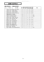
Page 42: ...WB ASSY 1 2 2 4 8 15 SSA 555B 050C VARISTOR 1 1 1 1 2 Z 16 SSA 564A 132 FUSE CURRENT 1 1 1 2 4 F 3 15A 17 SSA 551A 163L SENSOR ASSY 1 1 1 2 4 INCL SENSOR ROOM TEMP HEAT EXCH 18 RKV 504A 500 HARNESS ASSY POWER 1 1 1 1 2 19 SSA 561B 713 BLOCK TERMINAL 1 1 1 2 2 20 RKX 011G 001 LABEL WIRING 1 21 RKX 503A 001 DISPLAY ASSY 1 1 1 2 3 22 RKX 505A 003 PWB ASSY DISPLAY 1 2 2 4 8 23 RKJ 941F 001 SPRING LEAF...

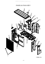
Page 43: ...CRBE0233 1 7 2 16 3 7 4 5 6 15 8 14 12 10 13 11 18 17 17 17 9 PANEL FAN ASSY 41 All manuals and user guides at all guides com ...

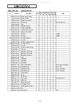
Page 44: ...REW TAP 17 4 8 7 SSA 913A 034C SCREW TAP 3 4 12 8 RCS 124A 500 PANEL ASSY TOP 1 1 1 1 2 9 RCS 116A 006 BRACKET ASSY 1 10 SSA 511J 221 MOTOR AC 1 2 2 4 8 11 RCS 141A 500 PLATE BAFFLE 1 12 SSA 431B 213 PROPELLER 1 1 1 2 4 13 RSA 914B 002 NUT FLANGE 1 14 RCS 111A 001D BASE ASSY 1 1 1 1 2 15 RSA 011H 016A LABEL NOTICE 1 16 RCS 116A 502 BRACKET 1 17 W011D04X008 TAP SCREW CRS TRS 2 4 4 8 18 D100X20X036R...

Page 45: ...CRBE0234 1 2 3 21 4 5 6 8 7 19 13 22 20 18 9 10 11 14 15 16 17 23 12 GAS LIQ HEAT EXCH CONTROL 43 All manuals and user guides at all guides com ...

Page 46: ...001 NUT FLANGE 2 11 RMC 941C 002 CUSHION RUBBER 3 12 RCS 154D 001 INSULATION COMP 1 13 RSA 932C 005 GASKET COVER 1 14 RSA 947K 006 COVER TERMINAL 1 1 1 2 4 15 RSA 914C 002 NUT FLANGE 1 16 SSA 552A 842 CAPACITOR RUNNING 1 1 1 1 2 CFO 1 8MF 450VAC 17 SSA 552A 843A CAPACITOR RUNNING 1 1 1 1 2 CC 25MF 370VAC 18 RSA 533B 004 PROTECTOR MOTOR 1 1 1 1 2 19 SSA 561B 669 BLOCK TERMINAL 1 1 1 2 2 20 RCS 504A...

Page 47: ...CRBE0239 1 7 2 16 3 7 4 5 6 15 8 14 12 10 13 11 17 17 17 9 PANEL FAN ASSY 45 All manuals and user guides at all guides com ...

Page 48: ...SA 913A 034B SCREW TAP 17 4 8 7 SSA 913A 034C SCREW TAP 3 4 12 8 RCS 124A 500 PANEL ASSY TOP 1 1 1 1 2 9 RCS 116A 006 BRACKET ASSY 1 10 SSA 511J 222 MOTOR AC 1 2 2 4 8 11 RCS 141A 500 PLATE BAFFLE 1 12 SSA 431B 213 PROPELLER 1 1 1 2 4 13 RSA 914B 002 NUT FLANGE 1 14 RCS 111A 001C BASE ASSY 1 1 1 1 2 15 RSA 011H 016A LABEL NOTICE 1 16 RCS 116A 502 BRACKET 1 17 W011D04X008 TAP SCREW CRS TRS 2 4 4 8 ...

Page 49: ...CRBE0235 23 1 2 3 4 22 5 6 7 9 8 20 14 21 19 10 11 12 15 16 17 18 13 GAS LIQ 24 HEAT EXCH CONTROL 47 All manuals and user guides at all guides com ...

Page 50: ...SSY 1 1 2 3 8 11 RSA 914C 001 NUT FLANGE 2 12 RMC 941C 002A CUSHION RUBBER 3 13 RCS 154D 002 INSULATION COMP 1 14 RSA 932C 005 GASKET COVER 1 15 RSA 947K 006 COVER TERMINAL 1 1 1 2 4 16 RSA 914C 002 NUT FLANGE 1 17 SSA 552A 842A CAPACITOR RUNNING 1 1 1 1 2 CFO 2 5MF 450VAC 18 SSA 552A 843B CAPACITOR RUNNING 1 1 1 1 2 CC 30MF 400VAC 19 RSA 533B 005 PROTECTOR MOTOR 1 1 1 1 2 20 SSA 561B 669 BLOCK TE...

Page 51: ...ROOM AIR CONDITIONING TECHNICAL MANUAL PARTS LIST Manual No 06 SRK T 056 All manuals and user guides at all guides com a l l g u i d e s c o m ...

Reviews: