background image

-

 7 

-

LO

MED

HI

AUTO

HI POWER

ECONO

ON

OFF

AM

PM

HI POWER TEMP

ECONO

AIR FLOW

CANCEL

ON

OFF

RESERVE

TIMER

TIME

ACL

FAN SPEED

ON

MODE

LO

MED

HI

AUTO

TIME

OFF

HI POWER

ECONO

ON

OFF

AM

PM

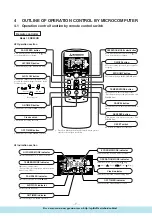
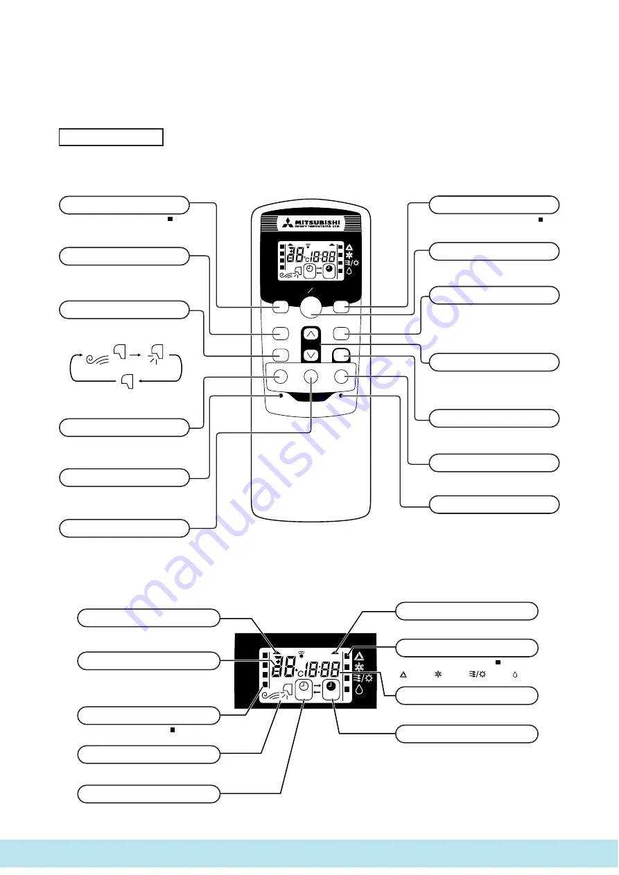
FAN SPEED button

Each time the button is pushed, the

 indi-

cator is switched over in turn.

The above illustration shows all controls, but in practice
only the relevant parts are shown.

OPERATION MODE select button

Each time the button is pushed, the

 indi-

cator is switched over in turn.

AIR FLOW button

This button changes the flap mode. When
pressed, this button changes the mode in the
following order:

ON/OFF button

Press for starting operation, press again for
stopping.

HI POWER button

This button changes the HI POWER mode.

ECONOMY button

This button changes the ECONOMY mode.

RESET switch

Switch for resetting microcomputer.

ON TIMER button

This button selects ON TIMER operation.

Clock switch

This switch for setting the clock.

OFF TIMER button

This button selects OFF TIMER operation.

TEMPERATURE button

This button sets the room temperature.
(This button changes the present time and
TIMER time.)

CANCEL button

This button cancels the ON timer and OFF
timer.

RESERVE button

This  button  sets  the  present  time  and
TIMER time.

S

 Indication section

OPERATION MODE indicator

Indicates selected operation with

 lamp.

(Auto) • 

(Cool) • 

(Heat) • 

(Dry)]

TEMPERATURE indicator

Indicates set temperature.
(Does not indicate temperature when operation
mode is on AUTO)

FAN SPEED indicator

Indicates set air flow rate with

 lamp.

AIR FLOW indicator

Shows selected flap mode.

HI POWER MODE indicator

Indicates during Hi power mode operation.

ECONOMY MODE indicator

Indicates during economy mode operation.

ON TIMER indicator

Indicates during ON TIMER operation.

Clock indicator

Indicates present time or timer setting time.

OFF TIMER indicator

Indicates during OFF TIMER operation.

Model SRK20HD

Remote controller

S

 Operation section

4

OUTLINE OF OPERATION CONTROL BY MICROCOMPUTER

4.1 Operation control function by remote control switch

(Air scroll)

(Swing)

(Flap stopped)

Все каталоги и инструкции здесь:

 http

:

//splitoff.ru/tehn-doc.html

Summary of Contents for SRC20HD

Page 1: ...OOM AIR CONDITIONER Collection data Manual No 05 SRK T 045 Split system air to air heat pump type SRK20HD Большая библиотека технической документации http splitoff ru tehn doc html каталоги инструкции сервисные мануалы схемы ...

Page 2: ...to restart function 8 4 4 Flap control 9 4 5 Comfortable timer setting 9 4 6 Outline of heating operation 10 4 7 Outline of cooling operation 13 4 8 Outline of dehumidifying operation 14 4 9 Automatic operation 15 4 10 Protective control function 15 5 APPLICATION DATA 17 5 1 Selection of location for installation 18 5 2 Installation of indoor unit 19 5 3 Installation of outdoor unit 21 5 4 Refrige...

Page 3: ...ither automatically decide operation mode such as cooling heating and thermal dry or operate in the operation mode before it has been turned to automatic control 3 Self diagnosis function We are constantly trying to do better service to our customers by installing such judges that show abnormality of operation as follows Series No Heat pump type Product capacity Wall mounted type Split type room a...

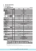
Page 4: ... control MC Thermostat Pilot lamp RUN Green TIMER Yellow HI POWER Green ECONO Orange Safety equipment O D mm in Liquid line φ6 35 1 4 Gas line φ9 52 3 8 Connecting method Flare connecting Attached length of piping Liquid line 0 4 m Gas line 0 33 m Insulation Necessary Both sides Drain hose Connectable Power source cord 2 5 m 3 cores with Earth Size Core number 1 5 mm2 4 cores Including earth cable...

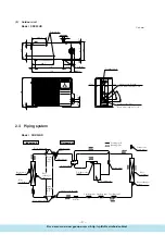
Page 5: ...t difference between outdoor unit and indoor unit Max 5m Outdoor unit is higher Max 5m Outdoor unit is lower Item Model 2 3 Exterior dimensions 1 Indoor unit Model SRK20HD VIEW A 117 5 580 117 5 148 5 216 5 216 5 216 5 8 2 44 5 236 1 5 7 450 450 67 5 42 7 47 2 175 44 5 216 5 216 5 216 5 148 5 53 5 Piping for Gas 397 1 ø9 52 Drain hose 540 ø16 Piping for Liquid 465 1 ø6 35 Piping hole ø65 Piping ho...

Page 6: ...ping system Outdoor unit Indoor unit Flare connecting Room temp sensor Heat exchanger Flare connecting Piping Liquid ø6 35 Heat exchanger sensor Piping Gas ø9 52 Service valve Gas Check joint 4 way valve Service valve Liquid Strainer Capillary tube Capillary tube Capillary tube Compressor Accumulator Discharge temp sensor Heat exchanger sensor Heat exchanger Outdoor air temp sensor Cooling cycle H...

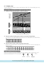
Page 7: ...nger How to obtain the cooling and heating capacity Example The net cooling capacity of the model SRK20HD with the piping length of 15m indoor wet bulb temperature at 19 0 C and outdoor dry bulb temperature 35 C is Net cooling capacity 2000 0 975 1 0 1950 w SRK20HD Length 15m Factor by air temperatures 15 ISO T1 Standard Condition Outdoor air W B temperature C W B 0 10 10 5 5 14 16 18 20 22 15 10 ...

Page 8: ... Th1 Th2 CNG Th4 Th5 Th6 CNB CNU Display Wireless R Amp 1 2 3 Black Brown Red Light blue White Yellow Green BK BR RD LB WH Y GN Color symbol Meaning of marks Symbol Parts name I Symbol Parts name Symbol Parts name CF I CM F FM I FMo SM Th 1 Th 2 Th 4 Th 5 Th 6 Tr Capacitor for FM I Compressor motor Fuse Fan motor Indoor Fan motor Outdoor Flap motor Room temp sensor Heat exchanger sensor Indoor uni...

Page 9: ...on selects OFF TIMER operation TEMPERATURE button This button sets the room temperature This button changes the present time and TIMER time CANCEL button This button cancels the ON timer and OFF timer RESERVE button This button sets the present time and TIMER time S Indication section OPERATION MODE indicator Indicates selected operation with lamp Auto Cool Heat Dry TEMPERATURE indicator Indicates...

Page 10: ...e operational status of the air conditioner immediately prior to it being switched off by a power cut and then automatically resumes operations at that point after the power has been restored 2 The following settings will be cancelled a Timer settings b High power operations Notes 1 The power blackout auto restart function is set at on when the air conditioner is shipped from the factory Consult w...

Page 11: ...e is found to be 5 min utes from the table shown above so that the starting time of next operation is determined as follows 15 min earlier 5 min 20 min earlier Current operation Correction value start time 4 5 Comfortable timer setting If the timer is set at ON when the operation select switch is set at the cooling or heating or the cooling or heating in auto mode operation is selected the comfort...

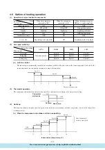
Page 12: ...n motor Flaps Display 52C Outdoor fan motor ON ON or OFF Lights up ON OFF ON ON or OFF Lights up ON ON OFF Stop position control Lights up or flashes OFF after stop mode OFF 4 way valve Depending on the stop mode ON Depending on the stop mode When the compressor command is OFF When the compressor command is ON When the compressor goes OFF due to an abnormal stop Functional components Item Air scro...

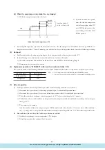
Page 13: ... exchanger sensor temperature is 5ºC or lower continuously for 3 minutes 4 The difference between the outdoor air temperature sensor temperature and the outdoor heat exchange sensor tempera ture is 4 5ºC 5 The compressor is running Also the number of times the compressor goes OFF is counted and when it reaches 10 or more times if the conditions in 1 2 and 3 above except that the outdoor heat excha...

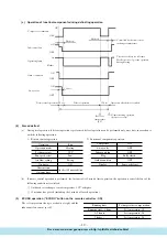
Page 14: ...unit fan Operating lamp Flashes Outdoor unit fan 4 way valve Defrost start operation Hot keep Defrost operation Operation after defrost is ended Normal heating operation defrost recovery Controlled by the indoor heat exchanger temperature The chart at left is for reference Hot keep control governs operation during heating Hot keep Recovery temperature 9ºC OFF OFF OFF ON ON Lit ON ON 120 sec 120 se...

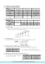
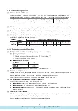
Page 15: ... Protective functions will actuate with priority even during the HI POWER operation Indoor fan motor Flaps Display 52C Outdoor fan motor ON ON or OFF Lights up ON OFF ON ON or OFF Lights up ON ON OFF Stop position control Lights up or flashes OFF after stop mode OFF 4 way valve Depending on the stop mode OFF Depending on the stop mode When the compressor command is OFF When the compressor command ...

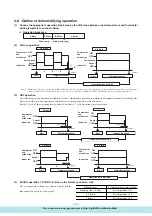
Page 16: ... OFF OFF 0 3 6 9 12 ON OFF OFF 0 12 Compressor and outdoor fan Set fan speed Indoor fan Start Temperature check Start Temperature check Compressor and outdoor fan Set fan speed Indoor fan Operation block decision C D Block A B Block minutes minutes Speed 1 Speed 1 20 seconds ON OFF OFF 0 4 8 ON OFF OFF 0 8 Compressor and outdoor fan Indoor fan D Block Compressor and outdoor fan Indoor fan C Block ...

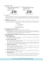
Page 17: ...umidifying a Operating conditions i Indoor heat exchanger temperature detected with Th2 is lower than 2 5ºC ii 3 minutes elapsed after the start of operation b Detail of anti frost operation Compressor OFF Indoor fan 1st speed Outdoor fan OFF 4 way valve Stop mode c Reset condition Indoor heat exchanger temperature Th2 is higher than 8ºC 2 Indoor fan motor protection When the air conditioner is op...

Page 18: ...oom temperature sensor If the temperature detected by the room temperature sensor is 20ºC or lower continuously for 15 seconds or longer while operation is stopped an error indication is displayed b Indoor heat exchanger sensor If the temperature detected by the indoor heat exchanger sensor is 20ºC or lower continuously for 15 seconds or longer while operation is stopped an error indication is dis...

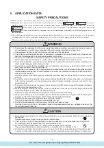
Page 19: ...d to electrical equipment and local regulations as well as the installation instructions and that only exclu sive use circuits are used Insufficient power source circuit capacity and defective installment execution can be the cause of electric shocks and fires Accurately connect wiring using the proper cable and insure that the external force of the cable is not conducted to the terminal connectio...

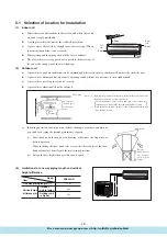
Page 20: ... 5 m r h Left side Right side 5 cm 10 cm 1 5 cm 6 5 cm Air inlet Air inlet Air Outlet 100 100 600 No obstacles Service space for electrical parts Unit mm Notes 1 Blowing out port and suction port on the back side of the unit can be installed at a distance of 10cm from walls In case the barrier is 1 2m or above in height or is overhead the sufficient space between the unit and wall shall be secured...

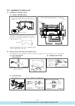
Page 21: ...m indoor side to outdoor side Indoor side Outdoor side Cut off the sleeve collar in case of drawing piping out to rear Cut off the sleeve collar that can be seen from beneath the unit Wall thickness 1 5 cm Indoor side Outdoor side Turn to tighten Paste View of sleeve when installed Inclined flange Sealing plate Sleeve Indoor side Outdoor side Look for the inside wall structures Intersediate suppor...

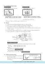
Page 22: ...leakage could re sult Since this air conditioner has been designed to collect dew drops on the rear surface to the drain pan do not attach the power cord above the gutter Gutter Wall Pipe accommodation section 1 Connect the connection wire securely to the terminal block If the wire is not affixed completely contact will be poor and it is dangerous as the terminal block may heat up and catch fire 2...

Page 23: ...unit firmly with foundation bolts wire etc 2 Connection of indoor and outdoor connecting wiring a Connect the wiring according to the number of the indoor terminal block Mis wiring may cause the burning damage and make sure to connect correctly Notes 1 To prevent the mis operation by noise when the connecting wire too long for indoor and outdoor Please hide the fixed wire in the pipe or use vinyl ...

Page 24: ...uid sides with hexagon headed wrench e Check for possible leakage of gas in the connection parts of both indoor and outdoor 4 Insulation of connecting portion 1 Cover the connection portion of the refrigerant piping with the pipe cover and seal them If neglecting to do so moisture occurs on the piping and water will drip out Additional refrigerant charge When refrigerant piping exceeds 7 5m conduc...

Page 25: ...230 240V Temp difference between return air and supply air C Note 1 The data are measured at following conditions Ambient air temperature Indoor side Cooling 27 C DB 19 C WB Heating 20 C DB Outdoor side Cooling 35 C DB 24 C WB Heating 7 C DB 6 C WB b When manipulating the remote controller mounted on a wall Make sure that it works normally i e transmission reception signal is audible before mounti...

Page 26: ...wer source and turn it on again in about 1 min and turn the unit on again YES No YES YES Does the trouble occur again Disconnect connectors and connect them again Operate the unit again after confirming that the fuse and the varistor equipped on PCB does not burn out Carry out checks according to detailed check process See later page Unit did not cool etc Is the power on Is the thermostat setting ...

Page 27: ...ressor faulty Overload operation 51C operation Gas shortage Defective discharge pipe sensor Compressor lock Closed service valve Broken signal wire Defective indoor outdoor unit PCB 3 Inspection procedures corresponding to detail of trouble Sensor error Broken sensor wire connector poor connection Shortcircuit Broken wire Is connector connection good YES YES NO NO Replace PCB Correct connection Re...

Page 28: ...ge pipe sensor Does trouble persist after charging gas Clogged capillary tube etc Indoor fan motor error Defective fan motor defective PCB YES YES NO NO Is connector connection good Is voltage applied to fan motor Defective fan motor Correct connector connection Defective indoor unit PCB Outdoor unit abnormal Compressor faulty compressor wiring disconnected Overload operation Is the refrigerant le...

Page 29: ...r operation command Heating Continuous compressor operation command is not released Cooling System can be operated normally Heating High pressure control mode b Outdoor unit Phenomenon sensor Shortcircuit Broken wire Cooling System can be operated normally Heating Defrosting is not performed Cooling System can be operated normally Heating Defrosting is not operated All modes Can be operated Operat...

Page 30: ... 220 230 240V Signal Between 2 3 Changing between DC 0 Approx 12V 6 How to make sure of remote controller 1 Is remote controller normal YES Again pushing operating switch Operating the unit NO Does unit ON OFF button operates Operating the unit NO NO YES YES Remote controller defects Abnormality is not found Replace the display Control problem on indoor unit Is the unit operable with remote contro...

Page 31: ...it after observing that gas is blow out from the loosened portion e Open the valve 1 and 3 after discharging air from the charge hose A then the gas refrigerant begins flowing from the cylinder into the unit Be sure to erect the refrigerant cylinder upright to let gas refrigerant flow into the unit f When refrigerant has been charged into the system to some extent refrigerant flow becomes stagnant...

Page 32: ...MEMO Все каталоги и инструкции здесь http splitoff ru tehn doc html ...

Page 33: ...ER Air Conditioning Refrigeration Systems Headquarters 16 5 2 chome Kounan Minato ku Tokyo 108 8215 Japan Fax 03 6716 5926 Большая библиотека технической документации http splitoff ru tehn doc html каталоги инструкции сервисные мануалы схемы ...

Reviews: