-
24
-
Adjustment of the installation board in the horizontal
direction is to be conducted with four screws in a
temporary tightened state.
5.2 Installation of indoor unit
(1)
Installation of installation board
(a)
Fixing of installation board
(2)
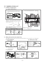
Drilling of holes and fixture sleeve (Option Parts)
When drilling the wall that contains a metal lath, wire lath or metal plate, be sure to use pipe hole sleeve sold separately.
(a)
Drill a hole with ø65
whole core drill
(b)
Adjusting sleeve length
Adjust so that board will be level by turning the board
with the standard hole as the center.
Standard hole
(c)
Install the sleeve
(Inserting sleeve)
(* *In *Sealing plate)
Note (1) Drill a hole with incline of 5 degree from
indoor side to outdoor side.
Indoor side
Outdoor side
Cut off the sleeve
collar in case of
drawing piping out
to rear.
Cut off the sleeve
collar that can be
seen from beneath
the unit.
Wall thickness
+ 1.5 cm
Indoor side
Outdoor side
Turn to
tighten
Paste
View of sleeve when installed
Inclined
flange
Sealing
plate
Sleeve
Indoor side
Outdoor side
Mating mark for
level surface
Level position (2 locations)
450
Look for the inside wall structures (Intersediate support or
pillar and firaly install the unit after level surface has been
checked.)
INSTALLATION SPACE (INDOOR UNIT)
(FRONT VIEW)
Unit : mm
Piping hole( 65)
Piping hole( 65)
Installation board
Indoor unit
53.5
Piping for Gas 380.6
Piping for Liquid 448.6
Drain hose 520( 16)
53.5
Space *
for service
Space
for service
44.5
252.2
7.5
8.3
Space for
service
50
Space for
service
100
102.5
585
102.5
133.5
450
206.5
202
450
138
44.5
43.2
39.3
200
65
15
* Leave extra space on the right side to enable removal of the lid screw.
Fixing on concrete wall
Use of nut anchor
Use of bolt anchor
Bolt
(M6
×
12)
Mounting
board
Nut
(M6)
Mounting
board
Max. 10
Piping for Liguid (20~50type) : ø6.35
Piping for Gas
(20~35type) : ø9.52
(40, 50type) : ø12.7

