- 16 -
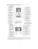
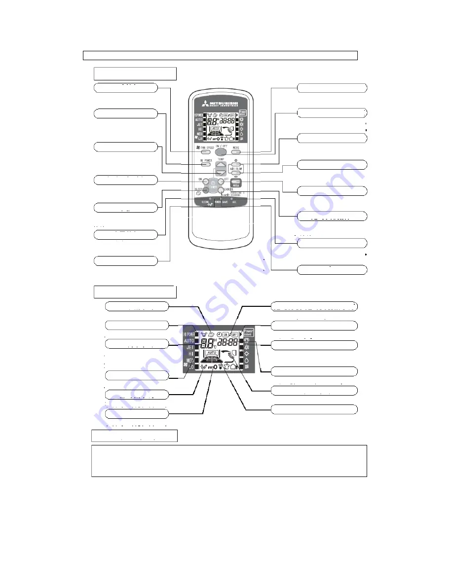
Operation and indication section for remote control
Operation section
FAN SPEED button
Each time this button is pressed,
■
displaying changes in order.
HI POWER button
This button is used to change
the HI POWER mode.
TEMP button
This button is used to set the room
temp. (or select the current time
and set time for timing operation.)
TIMER ON button
This button is used to select
the Timing ON operation.
SLEEP button
Press this button to switch to
the SLEEP operation.
CLEAN button
Press this button to switch to
the CLEAN mode.
POWER SAVE button
Press this button to switch to the
POWER SAVE mode.
Displaying section
SLEEP indicator
Appears in the SLEEP mode
HI POWER indicator
■
is used to indicate the HI POWER mode
TEMP indicator
Displays the set temperature
(No temperature is displayed in
the AUTO mode.
FAN SPEED indicator
■
is used to indicate the fan speed set.
CLEAN indicator
Appears in the CLEAN mode
KEY LOCK indicator
Appears in the CLEAN mode
Transmission method
MODE button
Each time this button is pressed,
■
displaying changes in order.
ON/OFF (luminous) button
Press this button to begin running;
press it again to stop running.
Up/Down air direction button
Press this button and the air flap begins
to swing upwards and downwards.
Left/Right air direction button
Press this button and the air flap begins to
swing to the left and the right.
AREA button
Press this button to set the air
regulation area in the room.
TIMER OFF button
This button is used to select the
Timing OFF operation.
ACL switch
Used to reset the microcomputer
CANCEL/KEY LOCK button
Press this button to cancel Timing ON/OFF
and SLEEP operations; press and hold it for 3
seconds to lock the functional keys.
Timing ON/ Timing OFF indicator
Appears in the Timing ON/ Timing OFF mode
Power Save indicator
Indicates the POWER SAVE mode
MODE indicator
■
is used to indicate the mode selected:
[AUTO/ COOLING/ HEATING/ DRYING/ BLOW]
TIME indicator
Displays the current time or the set time of the timer
AIR FLOW indicator
Displays the swinging mode of the flap
AREA indicator
Displays the air regulation area in the room
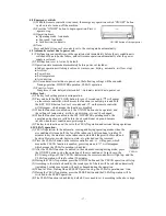
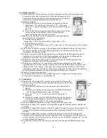
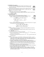
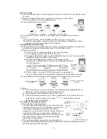
When the remote controller is pointed at the air conditioner, press a button on the remote controller and the signal will be
transmitted to the air conditioner. When the signal is received correctly, the air conditioner will issue the receiving sound. The
effective linear distance of transmission of the remote controller is 5 meters. The transmission head of the remote controller
should be pointed at the receiving head, otherwise, the receiving may be impacted.
● The above figure shows all
control contents for convenient
explanation. However, in actual
use, only related contents are
displayed.
Summary of Contents for SRC20MA-S
Page 10: ... 7 ...
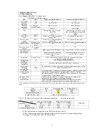
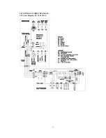
Page 15: ... 12 3 ELECTRICAL WIRING DIAGRAM 3 1 Circuit diagram 20 25 35MA S ...
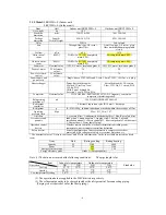
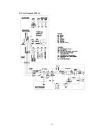
Page 16: ... 13 3 2 Circuit diagram 50MA S ...
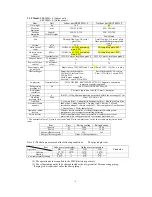
Page 62: ... 59 12 Check method for outdoor unit 1 Circuit diagram of 20 25 and 35MA S outdoor units ...
Page 63: ... 60 2 Circuit diagram of 50MA S outdoor unit ...
Page 84: ... 81 ...
Page 87: ... 84 ...
Page 90: ... 87 ...
Page 93: ... 90 ...
Page 96: ... 93 ...
Page 99: ... 96 ...
Page 102: ... 99 ...
Page 105: ... 102 ...
Page 107: ... 104 18 RYF141A005 PLATE BAFFLE 1 19 RYF111A003F BASE ASSY 1 ...
Page 111: ... 108 19 RYF111A003F BASE ASSY 1 ...
Page 115: ... 112 19 RYF111A003F BASE ASSY 1 ...
Page 119: ... 116 19 RYF111A002G BASE ASSY 1 ...

