- 2 -
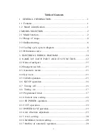
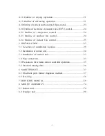
Table of Contents
1. GENERAL INFORMATION…………..……………………….……1
1.1 Features……………………………………..……………………..…1
1.2 Model identification………………………………………………1
2 MODEL SELECTION…………………………………………………2
2.1 Model function..…………..…….……..………………………..……2
2.2 Range of usage……………………………………………..………6
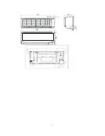
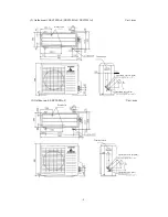
2.3 Outline drawing……………………………..……………………..…6
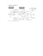
2.4 Cooling cycle system diagram…….………………..…………...…8
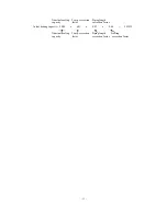
2.5 Performance curve……………………………………………………9
3 ELECTRICAL WIRING DIAGRAM……………………………….10
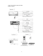
4 NAME OF EACH PART AND ITS FUNCTION………….12
4.1 Name of each part………………………….......…………………....15
4.2 Emergency switch………………………….......…………………....15
4.3 Automatic restart……………..…………..………………………..15
4.4 Key lock………….…………..……..……………………………..15
4.5 CLEAN operation………………...……..…………………………..15
4.6 SLEEP operation……..……..…………………………….……..16
4.7 Timing off………...............................................................16
4.8 Timing on ...........................................................................17
4.9 Programmed timer........................................................................ 17
4.10 Current time setting.....................................................................18
4.11 HI POWER operation....................................................................18
4.12 JET operation.........................................................................18
4.13 POWER SAVE operation.................................................................19
4.14 Air direction adjustment..............................................................19
4.15 Area setting…......................................................................20
4.16 Installation location setting.............................................................20
4.17 Outline of automatic operation..................................................20
Summary of Contents for SRC20MA-S
Page 10: ... 7 ...
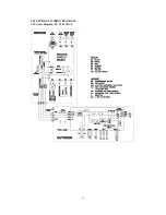
Page 15: ... 12 3 ELECTRICAL WIRING DIAGRAM 3 1 Circuit diagram 20 25 35MA S ...
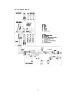
Page 16: ... 13 3 2 Circuit diagram 50MA S ...
Page 62: ... 59 12 Check method for outdoor unit 1 Circuit diagram of 20 25 and 35MA S outdoor units ...
Page 63: ... 60 2 Circuit diagram of 50MA S outdoor unit ...
Page 84: ... 81 ...
Page 87: ... 84 ...
Page 90: ... 87 ...
Page 93: ... 90 ...
Page 96: ... 93 ...
Page 99: ... 96 ...
Page 102: ... 99 ...
Page 105: ... 102 ...
Page 107: ... 104 18 RYF141A005 PLATE BAFFLE 1 19 RYF111A003F BASE ASSY 1 ...
Page 111: ... 108 19 RYF111A003F BASE ASSY 1 ...
Page 115: ... 112 19 RYF111A003F BASE ASSY 1 ...
Page 119: ... 116 19 RYF111A002G BASE ASSY 1 ...

