- 25 -
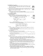
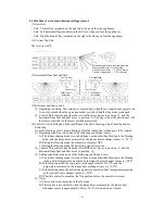
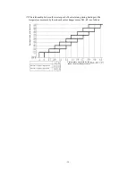
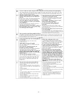
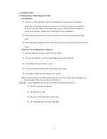
4.20 Outline of vertical and horizontal flaps control:
(1) Overview:
Sm1: Vertical flap (mounted on the right side when you face the appliance);
Sm2: Left horizontal flap (mounted on the left side when you face the appliance);
Sm3: Right horizontal flap (mounted on the right side when you face the appliance);
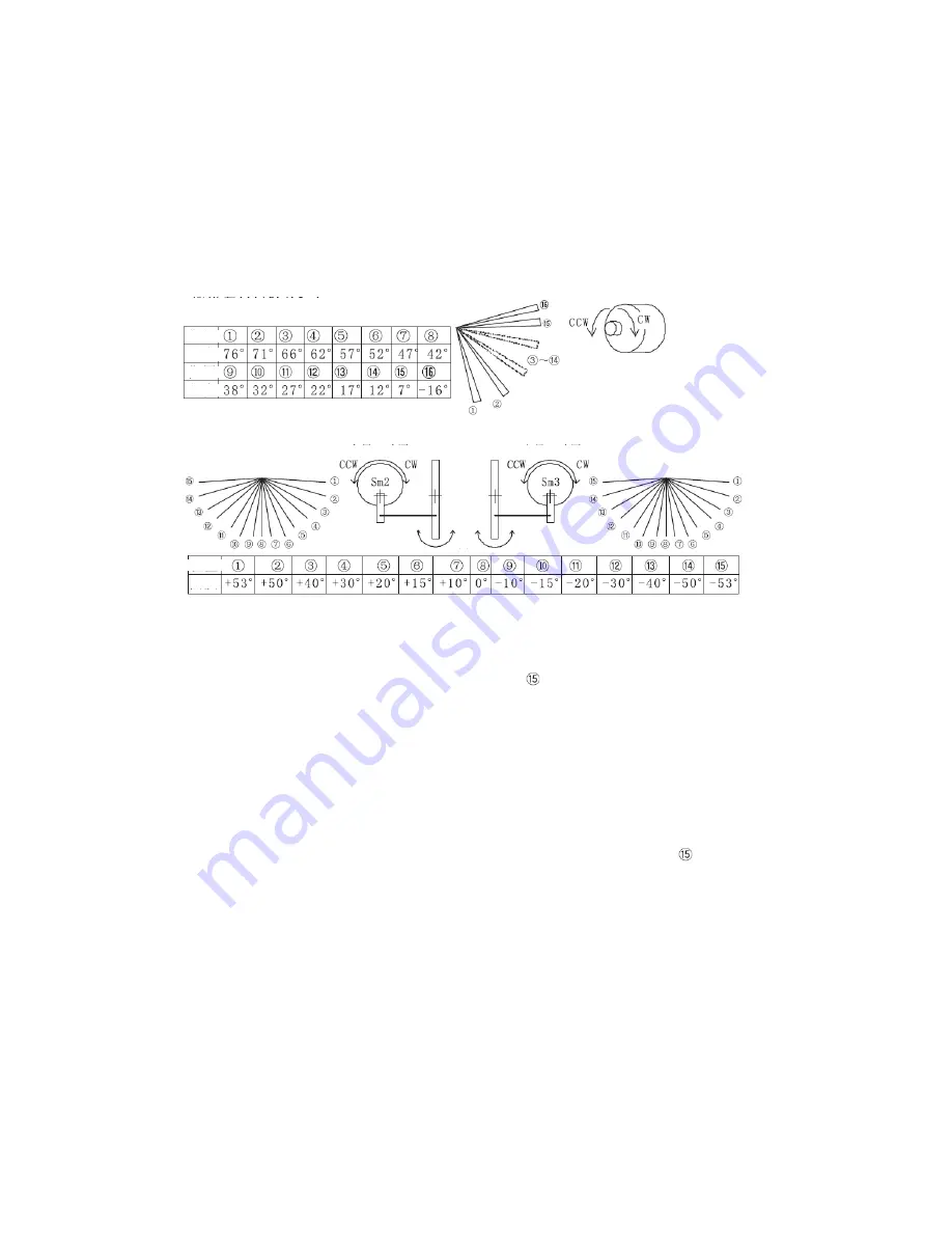
(2) Vertical flap Sm1:
The level set is 0
℃
.
(3) Horizontal flaps Sm2 and Sm3:
(4) Reference position control:
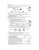
①
Beginning condition: This control is executed only when the air conditioner begins to run.
It is not executed when the operating mode is switched and the flap mode is changed.
②
Control: This control ends when the vertical flap Sm1 moves to position
①
and the
horizontal flaps Sm2 and Sm3 move to position
. The flaps stop at the position set with
the remote controller or the preset position memorized.
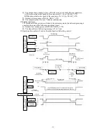
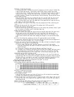
(4) Control of vertical flap and horizontal flaps at the start of heating, stop of heating and for
defrosting:
To avoid blowing cool air during heating before the indoor heat exchanger is fully warmed.
①
Beginning condition (when one of the following conditions is met):
A) The indoor running mode is switched from a mode other than Heating to the Heating
mode, and the temperature measured by the indoor heat exchanger sensor is < 28
℃
;
B) During the Heating mode, the compressor displays OFF;
C) During the Heating mode, the defrosting signal is received.
②
Control: This control ends when the vertical flap Sm1 moves to position
and the
horizontal flaps Sm2 and Sm3 move to position
⑧
.
③
Ending conditions (when one of the following conditions is met):
A) The indoor running mode is switched from a mode other than Heating to the Heating
mode, and the temperature measured by the indoor heat exchanger sensor is ≥ 28
℃
;
B) In the Heating mode, the compressor is changed from OFF to ON, and the
temperature measured by the indoor heat exchanger sensor is ≥ 28
℃
;
C) In the Heating mode, the defrosting signal is canceled, and the temperature measured
by the indoor heat exchanger sensor is ≥ 28
℃
;
D) When this control is canceled, the flap position before the control is restored.
④
Notes:
A) This control is not executed in the JIS mode;
B) This control is not executed when the temperature measured by the indoor heat
exchanger sensor is approximately below -28
℃
(disconnection of sensor).
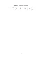
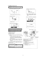
Position
Position
Angle
Angle
Relationship between rotation direction
of motor and state of vertical flap
Vertical flap closed
→
CCW of motor
Vertical flap opened
→
CW of motor
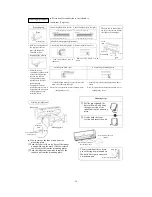
Position
Angle
For left flap
For right flap
Wide-angle
direction
Wide-angle
direction
F
ix
ed
p
o
in
t
d
ir
ec
ti
o
n
Summary of Contents for SRC20MA-S
Page 10: ... 7 ...
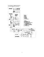
Page 15: ... 12 3 ELECTRICAL WIRING DIAGRAM 3 1 Circuit diagram 20 25 35MA S ...
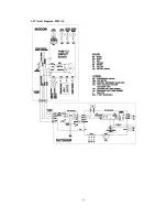
Page 16: ... 13 3 2 Circuit diagram 50MA S ...
Page 62: ... 59 12 Check method for outdoor unit 1 Circuit diagram of 20 25 and 35MA S outdoor units ...
Page 63: ... 60 2 Circuit diagram of 50MA S outdoor unit ...
Page 84: ... 81 ...
Page 87: ... 84 ...
Page 90: ... 87 ...
Page 93: ... 90 ...
Page 96: ... 93 ...
Page 99: ... 96 ...
Page 102: ... 99 ...
Page 105: ... 102 ...
Page 107: ... 104 18 RYF141A005 PLATE BAFFLE 1 19 RYF111A003F BASE ASSY 1 ...
Page 111: ... 108 19 RYF111A003F BASE ASSY 1 ...
Page 115: ... 112 19 RYF111A003F BASE ASSY 1 ...
Page 119: ... 116 19 RYF111A002G BASE ASSY 1 ...

