- 27 -
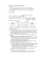
(2) Priority of rotate speed control:
Error response control > Outdoor fan control in compressor soft start control > Outdoor fan
control in defrosting control > Outdoor fan control/indoor forcing outdoor fan running
control in stop mode > Outdoor fan control at start > Outdoor fan control at the low outdoor
temperature in cooling > Outdoor fan control under overload in cooling > Delayed speed
position switching > Outdoor fan control under overload in heating > Speed position control
(3) Error response control:
When the outdoor fan runs at a speed below 75 rpm for over 30 seconds, the inverter will
immediately stop output to the fan and indicate results of self-diagnosis; if this occurs 3
times, it will send the error code to the indoor unit; if the speed exceeds 75 rpm once before
the 3 times, recount will be conducted.
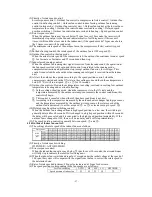
(4) The minimum rotate speed of the outdoor fan in the compressor soft start control is speed
④
.
(5) In the defrosting control, the rotate speed of the outdoor fan is OFF or speed
⑥
.
(6) Outdoor fan control in the stop mode:
When the actual rotate speed of the compressor is 0, the outdoor fan continues to run at speed
③
for 1 minute or 2 minutes and 55 seconds and then stop.
(7) Indoor forced running control:
When the outdoor fan running start signal is received from the indoor unit, the operation at
the fan speed received will begin, and this control is unrelated to the running mode,
compressor instruction and protection stop (except outdoor fan error, low voltage). This
control is canceled when the outdoor fan running cancel signal is received from the indoor
unit.
(8) At start, the outdoor fan operates according to the speed position control; when the
compressor is started and in the ON state in the cooling mode and the outdoor temperature is
below 22
℃
, it will run at speed
②
or
①
for 30 seconds.
(9) Outdoor fan control of low outdoor temperature in cooling, overload in cooling, low outdoor
temperature in heating and overload in heating:
①
In the cooling or heating mode, when the compressor is in the ON state and the
temperature measured by the outdoor air temp. sensor meets the control conditions, this
control will begin.
②
This control is canceled when either of the above conditions is not met.
③
According to the temperature measured by the outdoor heat exchanger liquid pipe sensor
and the temperature measured by the outdoor air temp. sensor, the rotate speed of the
outdoor fan is decreased (to as low as speed
②
or
①
) or increased (up to speed
⑧
).
(10) Delayed speed position switching control:
When the outdoor fan is changed from a high speed position to a low one, the switching is
generally delayed for 60 seconds. If it is changed to a high speed position within 60 seconds,
the delay will be canceled and it is converted to the high speed position immediately. If the
outdoor fan is changed to OFF, there will be no delay and it will stop immediately.
(11) The speed position control is generally between speed
③
and
⑧
.
4.24 Outline of indoor fan control:
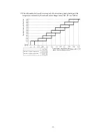
(1) The settings of rotate speed of the indoor fan are as follows:
(2) Priority of rotate speed switching:
HI POWER > AUTO/HI/ME/LO
(3) Error response control:
When the indoor fan runs at a speed below 75 rpm for over 30 seconds, the air conditioner
will fully stop to indicate the results of self-diagnosis.
(4) When the indoor fan is started and runs for 1 second under the initial voltage at the speed of
300 rpm, the system will compare with the signal from the fan to correct the rotate speed to
the determined one.
(5) Rate of rotate speed adjustment: 80 rpm for increase and 10 rpm for decrease.
(6) The speed positions corresponding to the fan speeds are as follows:
Air flow switching
AUTO
HI
ME
LO
HI POWER
Speed position of indoor fan
⑤
⑥
⑤
④
⑦
Speed position
Rotate
speed
(rpm)
Summary of Contents for SRC20MA-S
Page 10: ... 7 ...
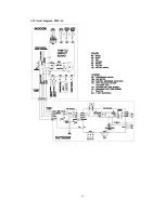
Page 15: ... 12 3 ELECTRICAL WIRING DIAGRAM 3 1 Circuit diagram 20 25 35MA S ...
Page 16: ... 13 3 2 Circuit diagram 50MA S ...
Page 62: ... 59 12 Check method for outdoor unit 1 Circuit diagram of 20 25 and 35MA S outdoor units ...
Page 63: ... 60 2 Circuit diagram of 50MA S outdoor unit ...
Page 84: ... 81 ...
Page 87: ... 84 ...
Page 90: ... 87 ...
Page 93: ... 90 ...
Page 96: ... 93 ...
Page 99: ... 96 ...
Page 102: ... 99 ...
Page 105: ... 102 ...
Page 107: ... 104 18 RYF141A005 PLATE BAFFLE 1 19 RYF111A003F BASE ASSY 1 ...
Page 111: ... 108 19 RYF111A003F BASE ASSY 1 ...
Page 115: ... 112 19 RYF111A003F BASE ASSY 1 ...
Page 119: ... 116 19 RYF111A002G BASE ASSY 1 ...

