- 32 -
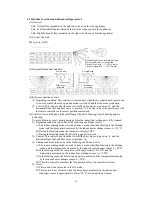
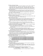
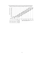
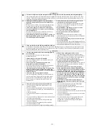
Selection of installation location
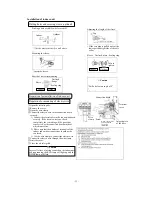
○ The appliance must be installed at a location with the vents and air intake being 10cm away from
walls.
(In case the fence is 1.2m or above in height, or is overhead, the sufficient space between the
unit and wall shall be secured.)
○ When the unit is installed, the space of the following dimension shall be secured.
○ Removal
①
Remove the air inlet grille.
②
Remove the 2 screws
securing the front panel.
③
Remove the 3 latches on
the upper part of the front
panel and remove the front
panel from the unit.
○ Installation
①
Remove the air filter.
②
Cover the unit with the
front panel.
③
Tighten the 2 screws to
secure the front panel.
④
Mount the air filter.
⑤
Mount the air inlet grille.
5.2 Installation of indoor unit
How to remove and install the front panel
Mountng of mounting plate
Air intake
10cm MIN
No obstacles (Service
space for electrical
parts)
10cm MIN
Air
intake
Air outlet
60cm MIN
Caution
If the wall is 1.2m or above in
height or there is a ceiling, the
sizes should be greater than
those indicated above.
Latches
Front panel
Air inlet grille
Screw
Screw
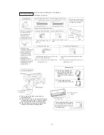
Fixing the mounting plate
Firstly find the position of
support or columella in the wall.
Check that the mounting
location
is level and then fix the
unit more securely.
Plane mating mark
○ In the loose state, use
four screws to adjust the
mounting plate
horizontally
.
Standard
hole
○ Turn the mounting
plate with the standard
hole as the center to
make it level.
Setting the relationship between
plate and indoor unit
Installation space
(Indoor unit) (Front view)
Service space Indoor unit
Service
space
Mounting plate
Pipe
hole
Gas piping
Liquid piping
Drainage pipe
Pipe hole
S
er
vi
ce
s
pa
ce
S
er
vi
ce
s
pa
ce
Fixing on the concrete wall
Using nut retainer Using screw retainer
Mounting plate
Mounting
plate
Nut
Nut
Max.
Summary of Contents for SRC20MA-S
Page 10: ... 7 ...
Page 15: ... 12 3 ELECTRICAL WIRING DIAGRAM 3 1 Circuit diagram 20 25 35MA S ...
Page 16: ... 13 3 2 Circuit diagram 50MA S ...
Page 62: ... 59 12 Check method for outdoor unit 1 Circuit diagram of 20 25 and 35MA S outdoor units ...
Page 63: ... 60 2 Circuit diagram of 50MA S outdoor unit ...
Page 84: ... 81 ...
Page 87: ... 84 ...
Page 90: ... 87 ...
Page 93: ... 90 ...
Page 96: ... 93 ...
Page 99: ... 96 ...
Page 102: ... 99 ...
Page 105: ... 102 ...
Page 107: ... 104 18 RYF141A005 PLATE BAFFLE 1 19 RYF111A003F BASE ASSY 1 ...
Page 111: ... 108 19 RYF111A003F BASE ASSY 1 ...
Page 115: ... 112 19 RYF111A003F BASE ASSY 1 ...
Page 119: ... 116 19 RYF111A002G BASE ASSY 1 ...

