- 35 -
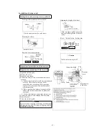
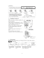
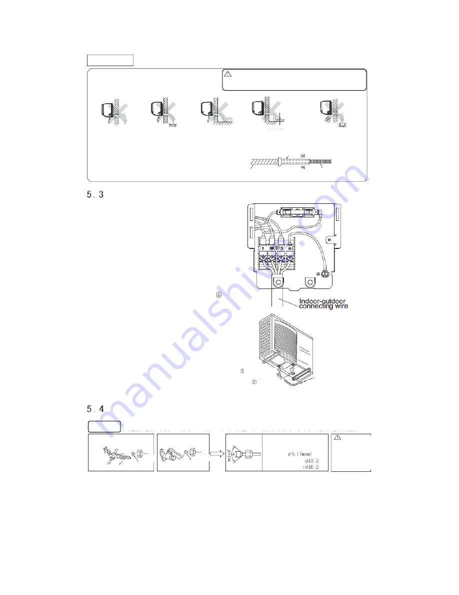
Drainage pipe
○ Mount the drainage pipe at a downward angle.
○ Avoid the following drainage pipe connections.
Caution
After all mounting steps, check
whether the drain is proper.
Otherwise, water leakage may occur.
Higher than as required
End of drainage pipe
in water
Undulating
Less than 5cm away
from ground
Odor
from sink
End of drainage
pipe in sink
Shielded-plate
tube
Drainage pipe
When exposed in
the room
Extended drainage pipe
○ Pour the water into the drain pan under the heat
exchanger and ensure the water is drained to outdoor
○ When the extended drainage pipe is in the room, be
sure to use a shielded-plate tube (to be mounted by
the user) to ensure thermal insulation.
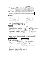
Installation of outdoor unit
○ Make sure that the unit is stable in installation. Fix
the unit to stable base.
○ When installing the unit at higher place or where
it could be toppled by strong winds, secure the unit
firmly with foundation bolts, wire, etc.
○ Perform wiring, making wire terminal numbers
conform to terminal numbers of indoor unit
terminal block.
○ Connect using ground screw located near
mark.
○ Never install the water elbow when the
temperature is below 0
℃
for several days in a row.
Water elbow
Groundwater-
preventing
piston
Ethylene hose
(Ethylene hose available on the
market)
(For heat pump type only)
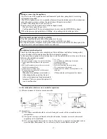
Pipe connection
Preparation
Before pipe connection, cover the pipes with tape, etc. to prevent dust, sand, etc.
from entering.
Indoor
Outdoor
Size A
Caution
Do not apply
refrigerating
machine oil to the
flared surface.
(Do not turn)
Remove
Press
Press
Remove
Liquid: side
Gas side:
Models 20-35:
Model 50
○ Screw off the flare
nut (liquid and gas
sides)
○ Screw off the flare
nut (liquid and gas
sides)
○ Mount the flare nut screwed off
onto the pipe to be connected to
form a trumpet shape.
Summary of Contents for SRC20MA-S
Page 10: ... 7 ...
Page 15: ... 12 3 ELECTRICAL WIRING DIAGRAM 3 1 Circuit diagram 20 25 35MA S ...
Page 16: ... 13 3 2 Circuit diagram 50MA S ...
Page 62: ... 59 12 Check method for outdoor unit 1 Circuit diagram of 20 25 and 35MA S outdoor units ...
Page 63: ... 60 2 Circuit diagram of 50MA S outdoor unit ...
Page 84: ... 81 ...
Page 87: ... 84 ...
Page 90: ... 87 ...
Page 93: ... 90 ...
Page 96: ... 93 ...
Page 99: ... 96 ...
Page 102: ... 99 ...
Page 105: ... 102 ...
Page 107: ... 104 18 RYF141A005 PLATE BAFFLE 1 19 RYF111A003F BASE ASSY 1 ...
Page 111: ... 108 19 RYF111A003F BASE ASSY 1 ...
Page 115: ... 112 19 RYF111A003F BASE ASSY 1 ...
Page 119: ... 116 19 RYF111A002G BASE ASSY 1 ...

