- 36 -
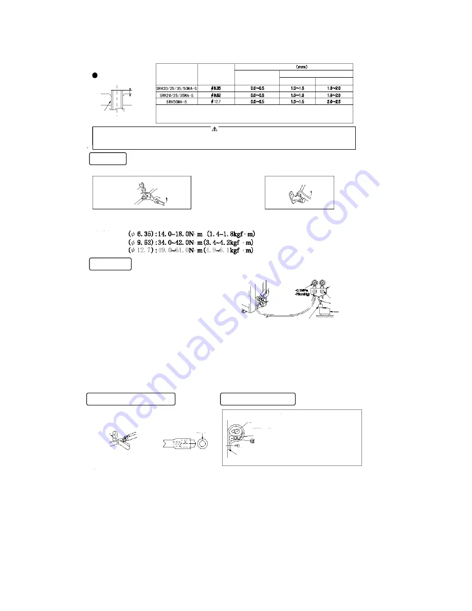
Flaring
Measurement B
Flaring
block
Copper
pipe
Model
Copper pipe
diameter
Measurement B
Clutch type flare tool
for R410A
Conventional (R22) flare tool
Clutch type
Wing nut type
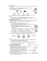
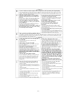
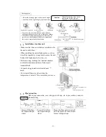
Use a flare tool designed for R410A or a conventional flare tool. Please note that measurement B (protrusion from the
flaring block) will vary depending on the type of flare tool in use. If a conventional flare tool is used, please use a copper
pipe gauge or a similar instrument to check protrusion so that you can keep measurement B to a correct value.
Caution
Do not apply excess torque to the flared nuts. Otherwise, the flared nuts may crack depending on the conditions and
refrigerant leak may occur.
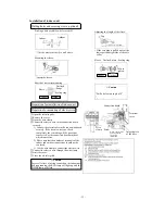
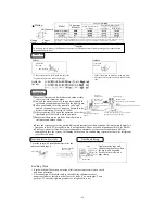
Connection
Indoor
Outdoor
Liquid side
Gas side
(Do not turn)
Liquid side
Gas side
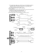
○ Connect the pipes on both liquid and gas sides.
○ Tighten the nuts to the following torque.
Liquid side
Gas side
○ Connect the pipes on both liquid and gas sides.
○ All torques are the same as on the indoor liquid
side.
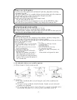
Air purging
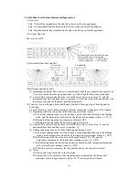
①
Secure all flare nuts on both indoor and outdoor sides
to prevent leaks from the pipes.
②
Connect the operation valves, charge hose, manifold
valve and vacuum pump as shown in the right figure.
③
Fully open Handle
Lo
for the manifold valve, and
pump a vacuum for over 15 minutes. Ensure that the
meter is indicating -76cmHg (-0.1MPa).
④
After vacuuming, fully open the operation valve (both
liquid and gas sides) with a hexagon wrench.
⑤
Ensure that there are no gas leaks from the joints in
the indoor and outdoor units.
Compound
pressure gauge
Operation valve
(2-way valve)
Gauge manifold
(Designed specifically for R410A)
Pressure gauge
Operation valve
(3-way valve)
Service port
Charge hose
(Designed specifically for
R410A)
Vacuum pump adapter (Anti-reverse flow type)
(Designed specifically for R410A)
Handle
Hi
Charge hose (Designed specifically for R410A)
Handle
Lo
● Since the system uses service ports differing in diameter from those found on the conventional models, a
charge hose (for R22) presently in use is not applicable. Please use one designed specifically for R410A.
● Please use an anti-reverse flow type vacuum pump adapter so as to prevent vacuum pump oil from
running back into the system. Oil running back into an air-conditioning system may cause the refrigerant
cycle to break down.
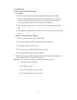
Heat insulation for joints
Finish and fixing
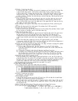
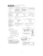
Cover the joint with insulation material for the
indoor unit and tape it.
Vinyl tape
Position so the slit
comes on top.
Apply exterior tape and
shape along the place where
the pipes will be routed.
Secure to the wall with a
pipe clamp.
Pipe clamp
Pipes
Exterior tape
Drainage pipe
Tapping screw
Ground wire
Crossover wires
Earthing Work
○ Earth work shall be carried out without fail in order to prevent electric shock
and noise generation.
○ The connection of the earth cable to the following substances causes
dangerous failures, therefore it shall never be done. (City water pipe, Town
gas pipe, TV antenna, lightning conductor, telephone line, etc.)
Summary of Contents for SRC20MA-S
Page 10: ... 7 ...
Page 15: ... 12 3 ELECTRICAL WIRING DIAGRAM 3 1 Circuit diagram 20 25 35MA S ...
Page 16: ... 13 3 2 Circuit diagram 50MA S ...
Page 62: ... 59 12 Check method for outdoor unit 1 Circuit diagram of 20 25 and 35MA S outdoor units ...
Page 63: ... 60 2 Circuit diagram of 50MA S outdoor unit ...
Page 84: ... 81 ...
Page 87: ... 84 ...
Page 90: ... 87 ...
Page 93: ... 90 ...
Page 96: ... 93 ...
Page 99: ... 96 ...
Page 102: ... 99 ...
Page 105: ... 102 ...
Page 107: ... 104 18 RYF141A005 PLATE BAFFLE 1 19 RYF111A003F BASE ASSY 1 ...
Page 111: ... 108 19 RYF111A003F BASE ASSY 1 ...
Page 115: ... 112 19 RYF111A003F BASE ASSY 1 ...
Page 119: ... 116 19 RYF111A002G BASE ASSY 1 ...

